Frontal Crash Analysis On BIW Component
Objective:
To Perform Frontal crash analysis on the given BIW component of the car and observe the changes in the model.
Theory:
Crashworthiness is the ability of a structure to protect its occupants during an impact. This is commonly tested when investigating the safety of the vehicles. Several criteria are used to assess crashworthiness prospectively, including the deformation patterns of the vehicle structure, the acceleration experienced by the vehicle during an impact, and the probability of injury predicted by human body models. A Crash test is a form of destructive testing usually performed in order to ensure safe design standards.
New Car Assessment Program (NCAP): is a government car safety program tasked with evaluating new automobile designs for performance against various safety threats.
Standard crash tests performed by NCAP:
1:Frontal offset testing (64 km/h proposed)
2.Side-impact testing
3.Pedestrian protection testing
4.Rear impact testing
5.Child dummy dynamic crash testing
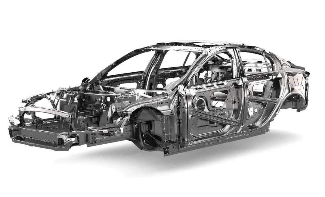
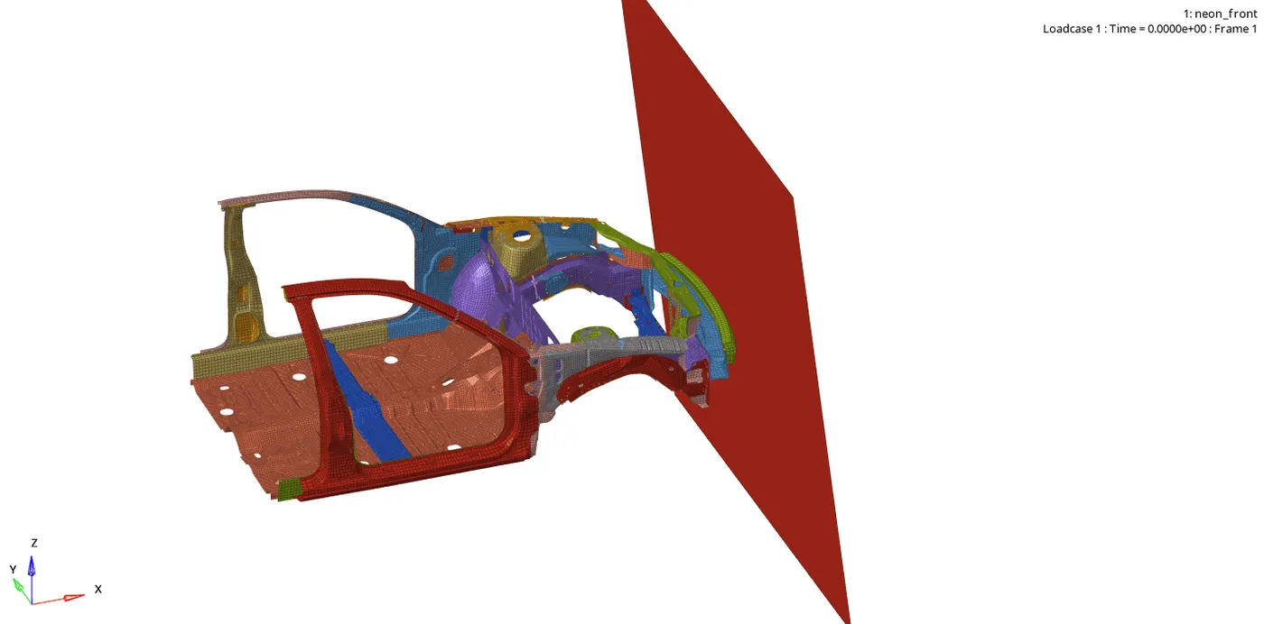
BIW Model :
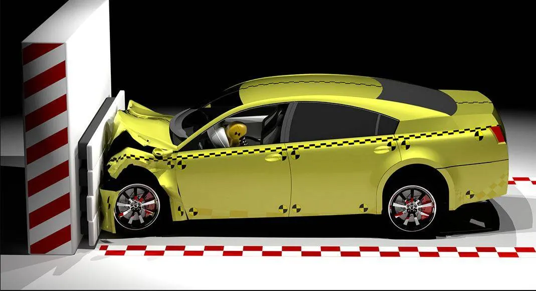
Frontal Crash:
Procedure:
Case setup & Execution:
1. Import the given model "neon_front_0000" into hypermesh.
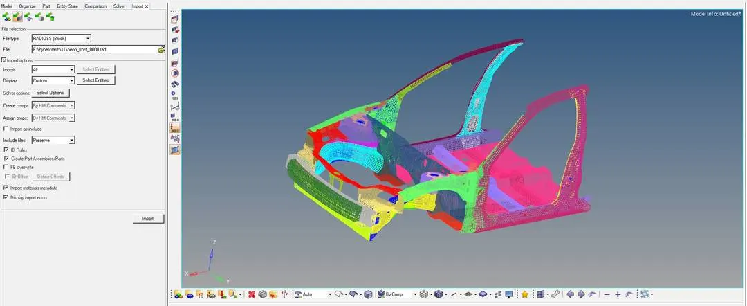
2. Simultaneously the model "neon_front_0000" is imported into hypercrash as well with the unit system as "Kg mm ms".
unsupported card found in the model is deleted.
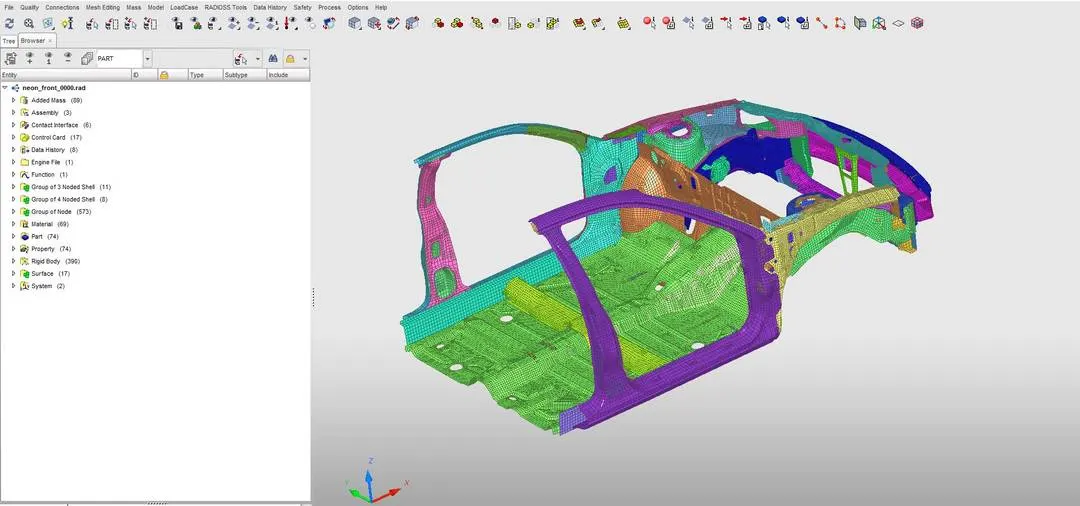
3. Once the model is imported into the hypercrash Model checker which is available in the Quality section is used to check for the errors that is available in the model to rectify them
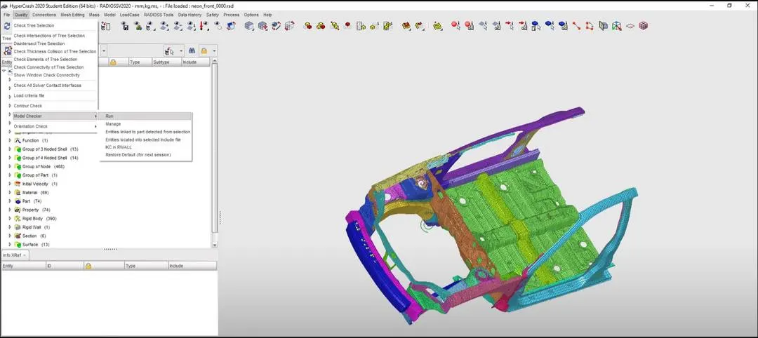
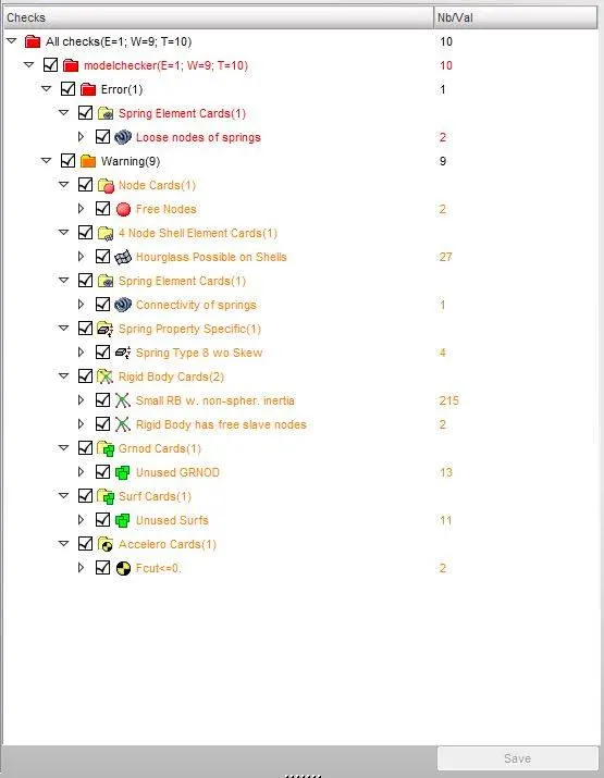
It can be noted that there is no major error is Seen in the model, so the errors can be neglected.
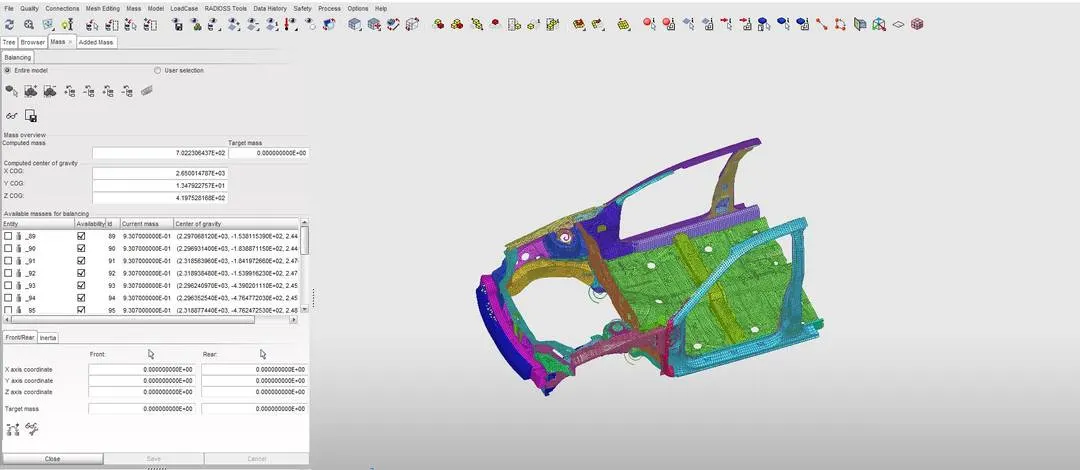
4. Balancing the center of Gravity:
- In hypercrash under mass menu balancing option is selected.
- Here the available mass in the model can be noted.
- To bring the Center of gravity point to the center, mass needs to be added manually.
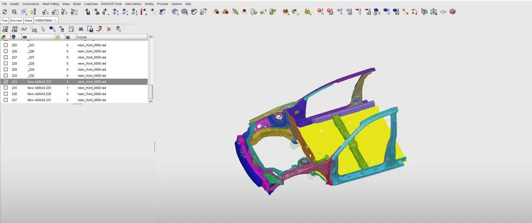
- To achieve the target mass of 700 Kgs, Added mass option in the Browser menu is used.
- In added mass, the major types used here are 0,1&3. (Type 0 = Mass is added to each node of the node group, Type 1 = Mass is distributed to each node of the node group, Type 3 = Additional mass distributed on part group)
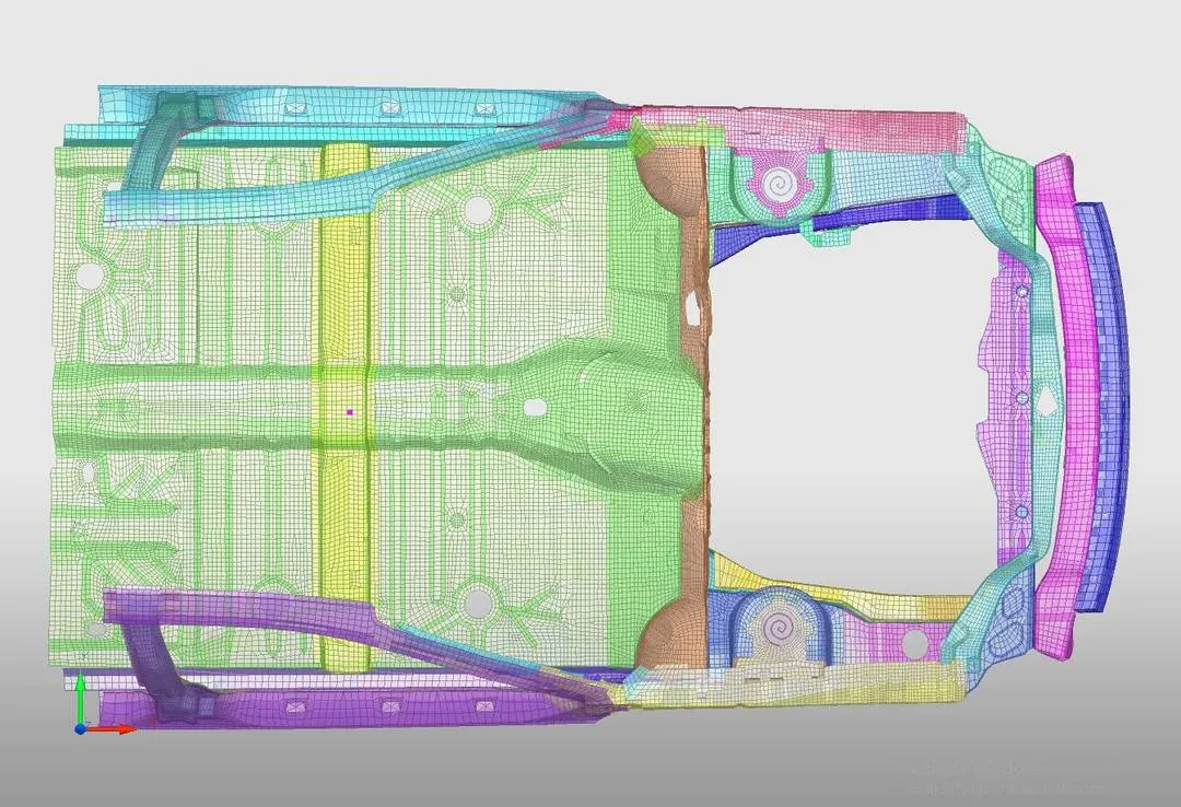
5. Creating the Rigid Wall:
- once the mass is balanced, a rigid wall with the friction of 0.1 needed to be created.
- In load cases, menu Rigid wall is selected and the following steps are carried out.
- Create a new object `rarr`Rigid Walls `rarr`Plane
- Then approximately center node in the bumper is selected and the normal is specified.
- In Slide option sliding with friction is selected and the friction is given as 0.1
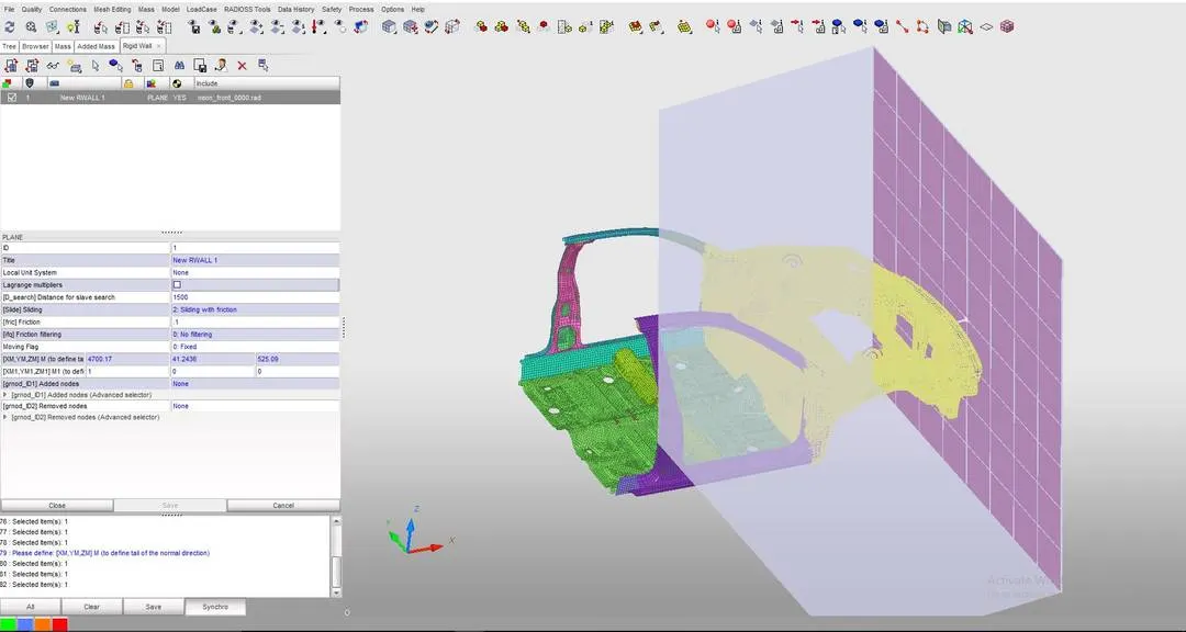
- The Important parameter which needed to be specified is "[D_search] Distance for slave search" which will consider the nodes as a slave up to a specified value
- Here D_search is given as 1500, If the D_search is given as zero no collision will take place in the model.
6. Creating the Initial velocity (Inivel):
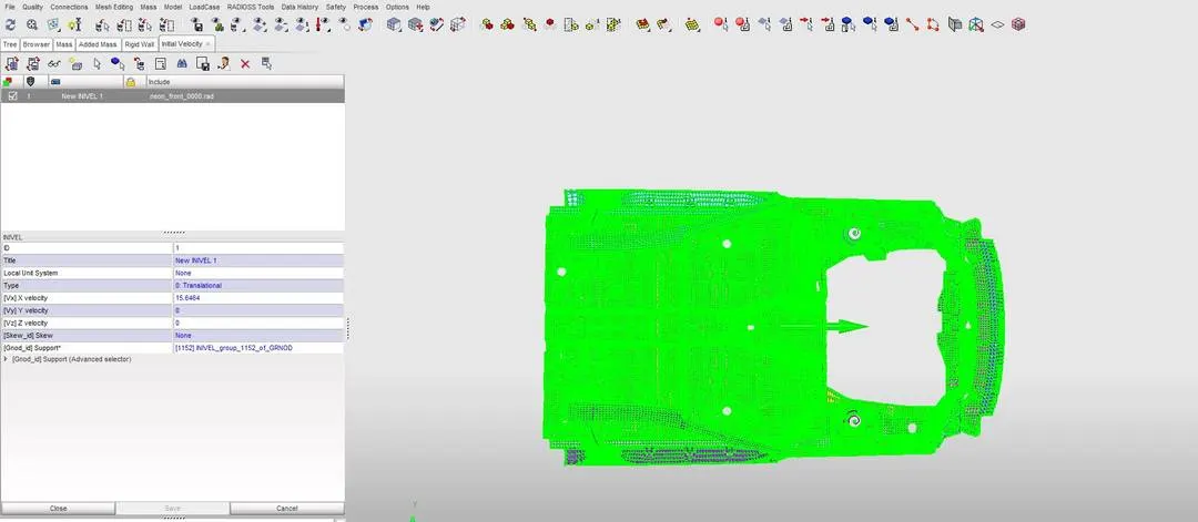
- After creating the rigid wall, there must be a velocity in which the car moves and crashes into the rigid wall.
- This is initial velocity is taken given as 35 mph which is converted into 15.6464 mm/ms
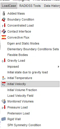
- The value can be applied to the model via the initial velocity option available in load cases.
7. Creating Contact Interface:
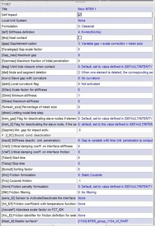
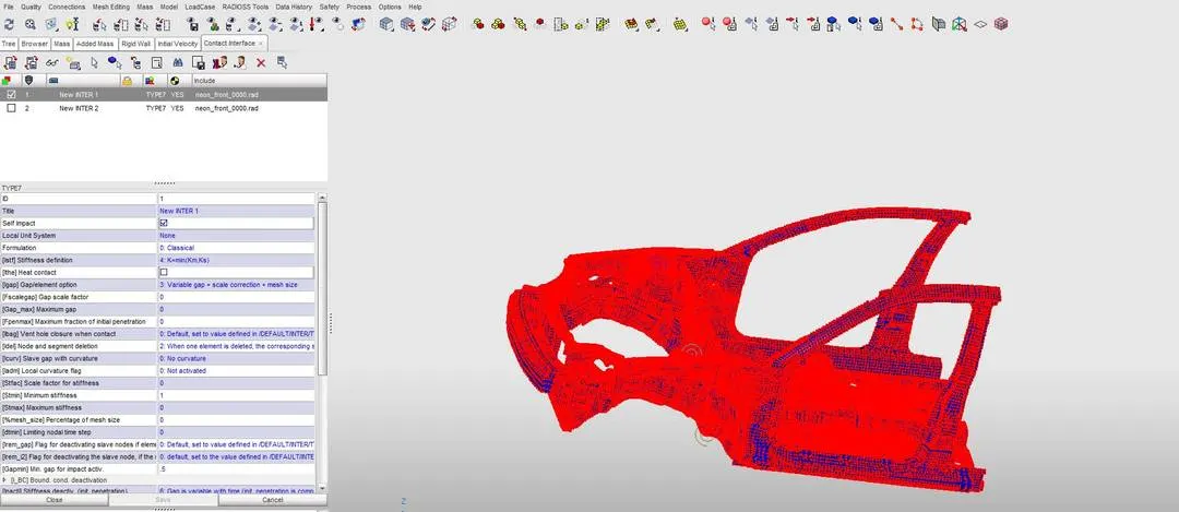
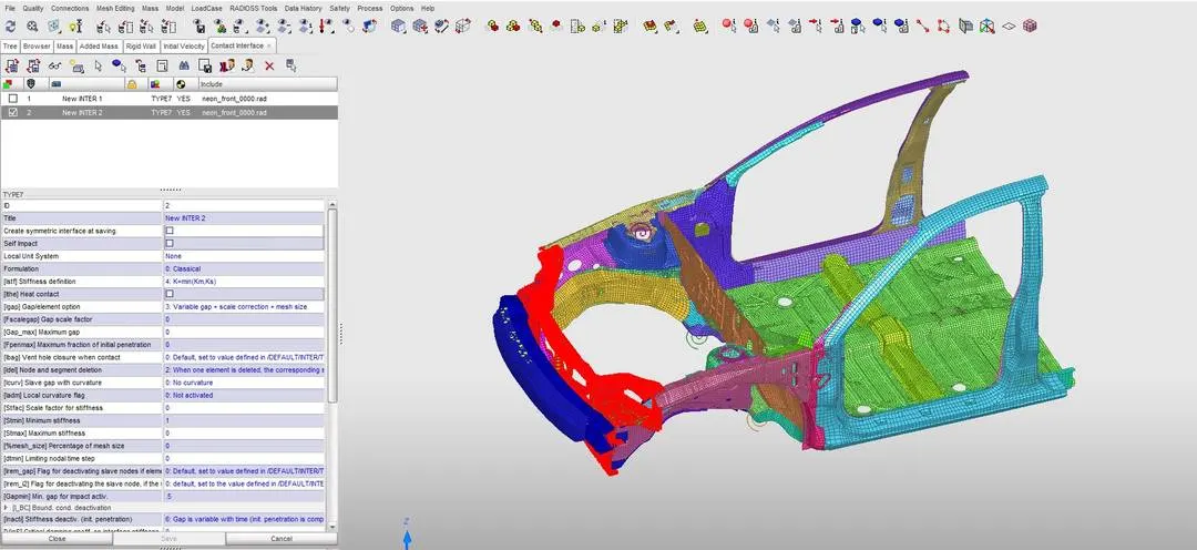
- Here the type of contact used is type 7, because of its high accuracy and correct physical representation.
- Two type 7 contact is created for one for self contact and the other for measuring the axial forces between the bumper and headlight frame.
- All the parameters values are set to be recommended values for crash application.
8. Creation of Cross section:
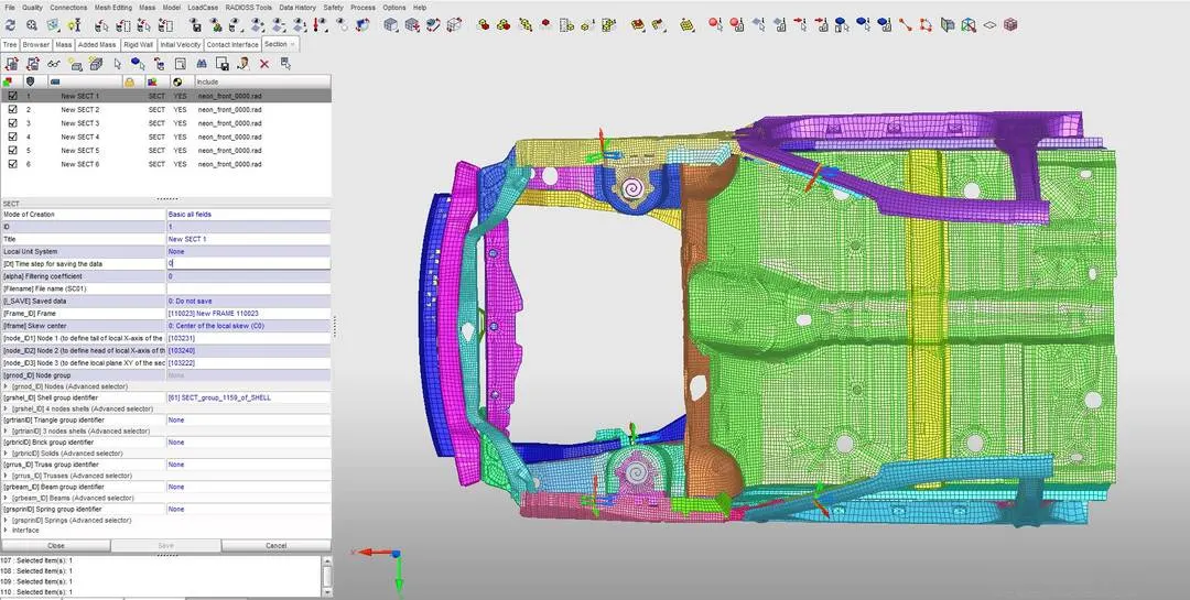
- cross section is needed to be created to observe the distribution of forces in different components such as Rails, Pillars and shotgun.
- The cross sectional normal force needed to be specified in the opposite direction of velocity.
- The following steps are carried out: Data history `rarr`Section `rarr`Section `rarr`Create a new object `rarr`Default section
- To create a section a frame needed to be created which specifies the local axis of the section. In create frame option the frame type is selected as moving frame (MOV) then three nodes N1, N2, N3 are selected.
- After this group of elements needed to create the section is selected.
9. Output Request:
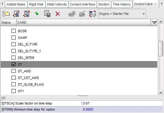
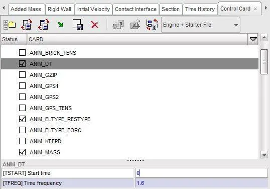
- In Control card we need to specify the time step = 0.0005 and time frequency = 1.6
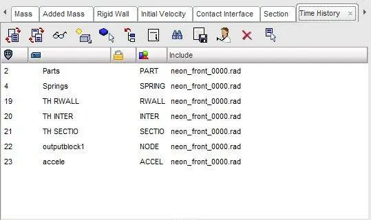
- Create TH for Rigid wall created.
- Create TH for node and select the node for finding intrusion.
- Create TH for Contact interface created.
- Create TH for all the section created.
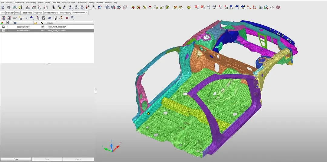
- Create TH for accelerometer created at B-Pillar.
10. Run the simulation:
- Since the simulation cannot be performed in hypercrash the model is exported as RADIOSS file, which is then imported into hypermesh to Run the simulation.
- In Hypermesh under Analysis panel Radioss option is selected.
- Specify the location in which the file needed to be saved, In the command options bar "-nt_4" is given, then radioss is selected to run the simulation.
- If the starter file showed any error that should be rectified then again the steps should be repeated.

Result and Analysis:
Open the file "neon_front_0001" in notepad to check Energy error, mass error and time elapsed.

TOTAL NUMBER OF CYCLES : 160001
** COMPUTE RUNTIME INFORMATION SUMMARY **
STARTER RUNTIME = 6.53s (00:00:06)
# 001 ENGINE RUNTIME = 8570.97s (02:22:50)
------------------------------
STARTER+ENGINE RUNTIME = 8577.50s (02:22:57)
since the energy error is -1.4% which is less than 15% so it is acceptable, also the mass error is found out to be 0.1785E-02
Since the energy error is acceptable, the model is moved for further observations by changing the environment to hyper view, then importing the file "neon_front.H3d"
Simulation Without any contour:
Displacement observation:
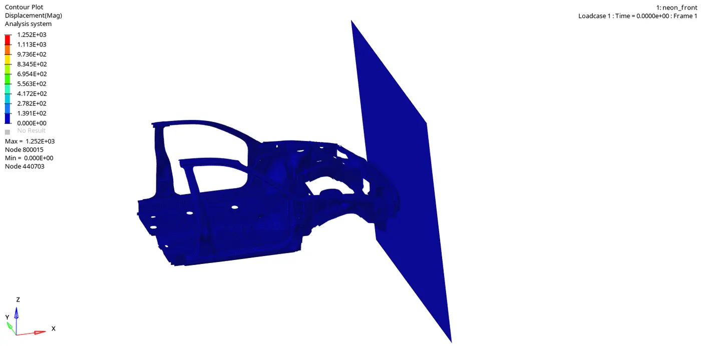
Maximum displacement: 1.252E+03 is at node 800015
Minimum displacement: 0.000E+00 is at node 440703
Von-mises Stress Observation:
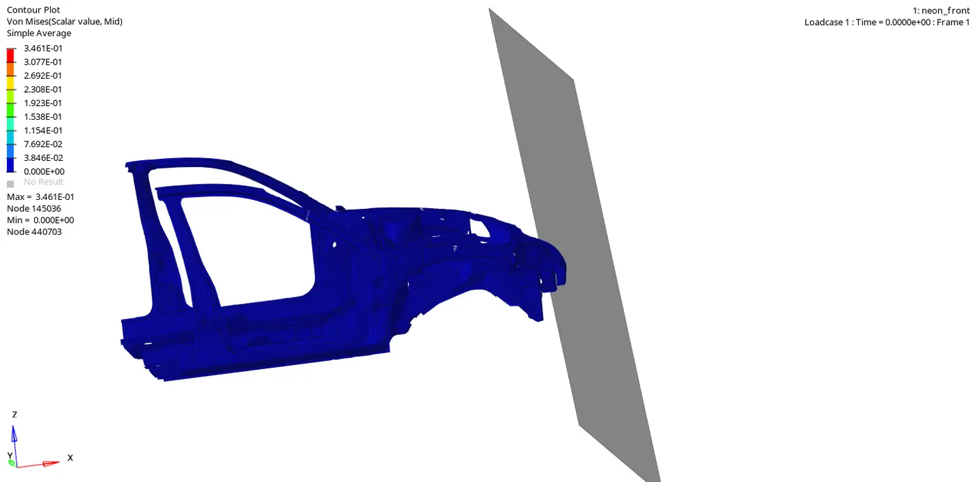
Maximum displacement: 3.461E+01 is at node 145036
Minimum displacement: 0.000E+00 is at node 440703
Graph 1: Time versus Internal energy, Kinetic energy, Contact energy, Hourglass energy and Total energy
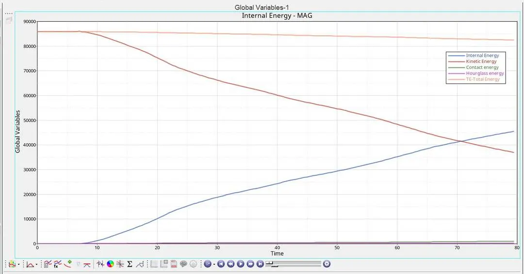
observations:
- Contact between the car and the rigid walls started at 8.5 ms
- The kinetic energy is constantly decreasing due to the deformation while the strain energy or internal energy is increasing during the impact.
- hence the total energy of the system remained balanced also a negligible spike in contact energy can be noted towards the end of the cycle.
- here no hourglass energy is formed due to the QEPH element formulation.
Graph 2: Time vs Interface (For observing the axial force)
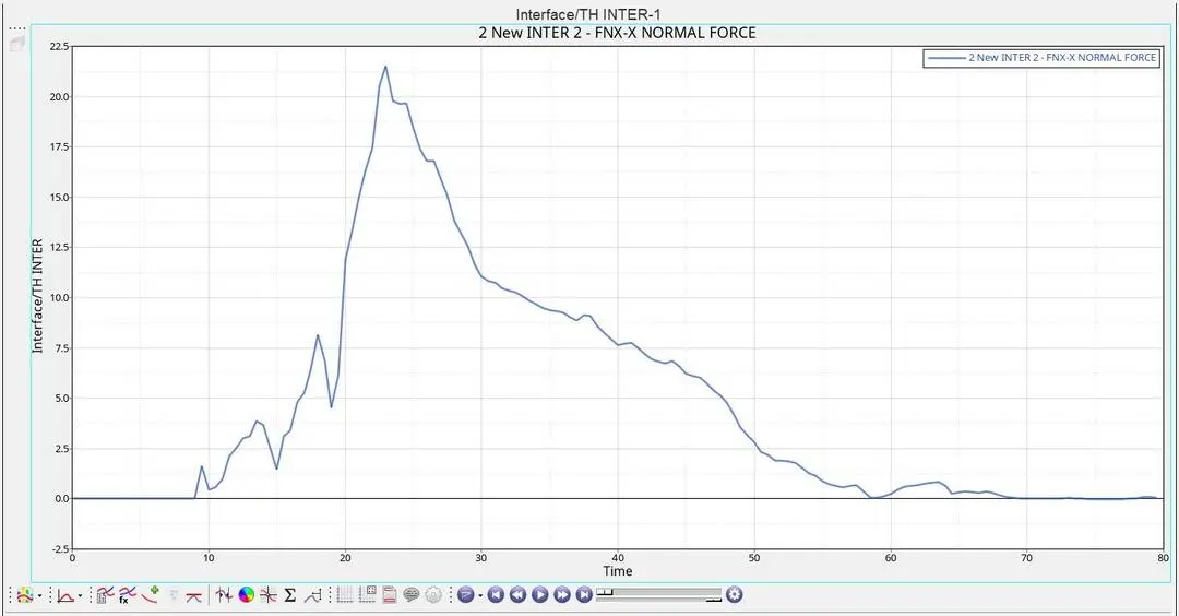
Observations:
- The axial force on the bumper is starting at 8.5 ms then suddenly a huge spike is noted on the graph
- this indicates that the forces are directly distributed between the bumper and other components of the car.
- the maximum peak force reaches at 23 ms during which the highest force was distributed to the car.
Graph 3: Time vs Displacement
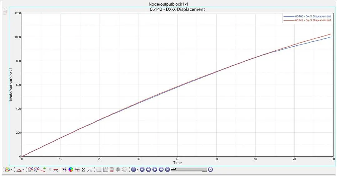
Observations:
- It is noted that the displacement increases over time, which indicates that the force is directly distributed on the nodes.
- The displacement reaches its maximum value of 1026.58 mm at 79 ms.
Graph 4&5: Time vs Acceleration
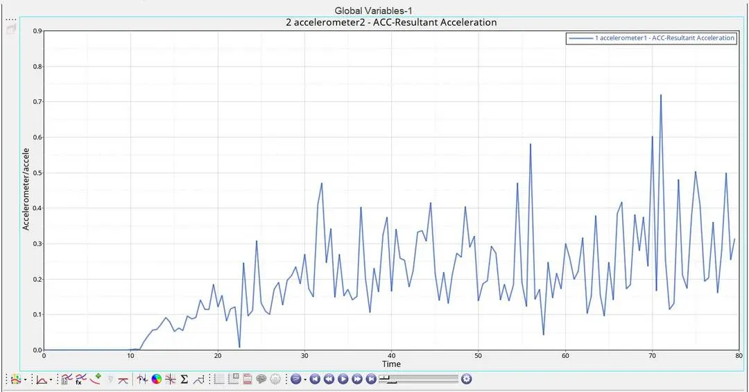
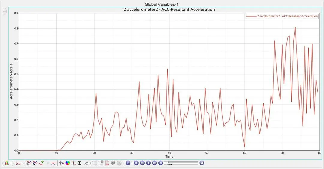
Observations:
- To observe the acceleration we have kept the accelerometer on the base of the b pillar
- here it is noted that the acceleration is irregular throughout the deformation in both the cases.
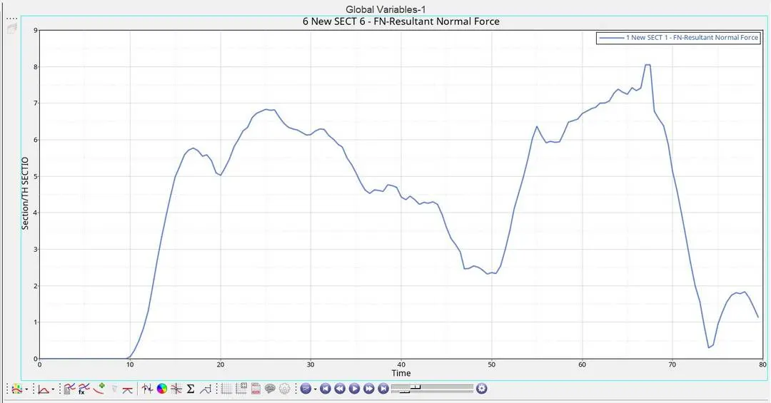
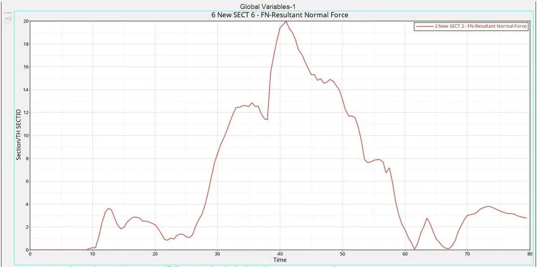
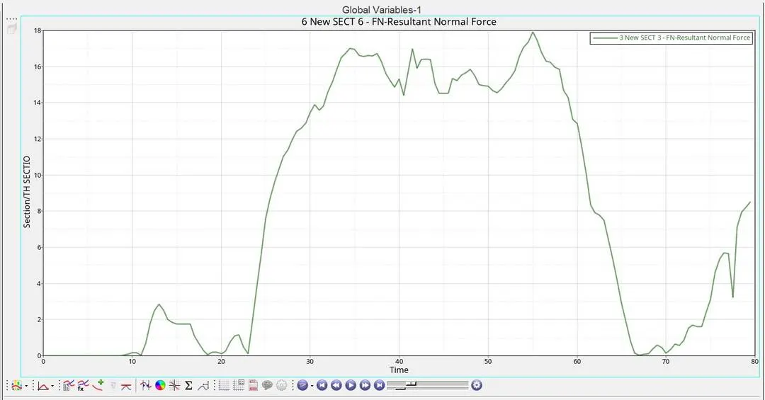
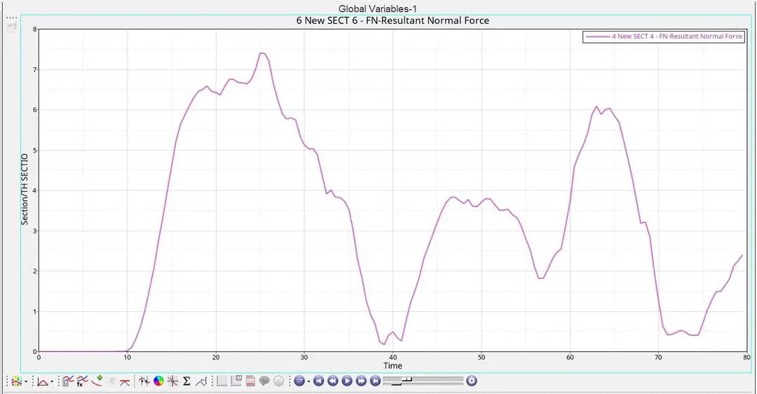
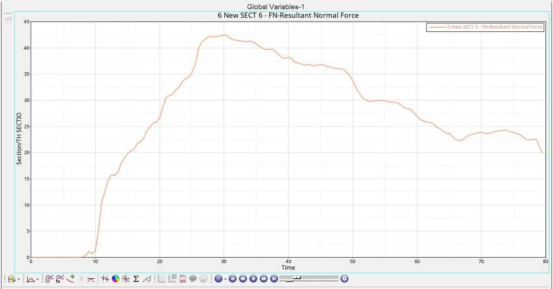
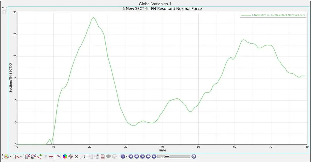
Graph 6,7,8,9,10&11: Time vs Sectional Forces
Observations:
- It can be noted that the sectional forces varies across different part from where it is located with respect to time.
- From the graph, it can be noted that the force absorbed is 100%
- The shotgun absorbs almost 35% of the forces and the rail absorbs nearly 40% of the forces and the rest are transferred to the base.
Conclusion:
Performed Frontal crash analysis on the given model of the car and it can be seen from the results and graph observations that the given Frontal BIW fails the frontal impact test.