FRONTAL CRASH ON BIW COMPONENT
AIM:-To perform the crash analysis on the car BIW component and observe the changes in the model with respective the simulation and graph
Theory:-
FMVSS -FEDELAR VEHICLE MOTOR STANDARDS
It is a vehicle regulatory organisation which is used to perform a crash test on the model and see whether people under-car are safe or not while (or) under collision. The frontal impact test is done to see the safety of the driver and pillion driver
The process of performing the vehicle test is to as per the standard the vehicle must drove at 33mph and it must directly collide with the wall which is rigid
As after collision of the car with the wall the large resistive force will be transferred to the wall and the purpose of the frame is to distribute the force correctly and it must tend to travel all forces to the bottom of the frame, otherwise, the total force will be transferred to the driver cabin and the driver will be injured
Nowadays there many organization are there like
NHTSA (NATIONAL HIGHWAY TRAFIC ADMINISTRATION)
NCAP(NEW CAR ASSESSMENT PROGRAM)
IIHS(INSURANCE INSTITUTE OF HIGHWAY SAFETY) etc...
As of now, India is also going to start a separate assessment program likely it is called BHARATH.N.C.A.P, everyone has their own different standards
TYPES OF CRASHES DONE IN THE VEHICLE
1.FRONTAL CRASH
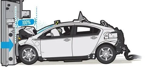
1.frontal impact at speeds up to 30 mph is conducted with various sizes of unbelted dummies.
2.The NCAP test occurs at 35 mph with belted dummies.
2.SMALL-OVERLAP FRONTAL IMPACT
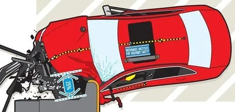
3.MODERATE-OVERLAP FRONTAL IMPACT
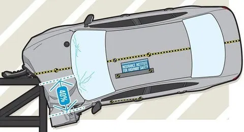
1.At 40 mph, the car strikes a barrier that overlaps 40 percent of its nose.
2.The contact area is covered with a deformable aluminum honeycomb to simulate crashes into objects more forgiving than concrete blocks
4.SIDE IMPACT
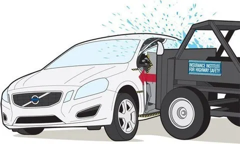
1.In FMVSS 214, a 3000-pound moving fixture with a crushable front surface hits the side of the test vehicle at 33.5 mph and an angle of 63 degrees, simulating a 30-mph T-bone collision.
2.The fixture slams home at 38.5 mph in the NCAP test.
3.The IIHS uses a 3300-pound sled moving at 31 mph and a 90-degree angle
5.ROOF CRASH
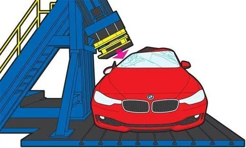
1.To achieve a Good rating, the roof must withstand a load four times the vehicle’s weight before crushing five inches.
2.Resisting a load 2.5 times vehicle weight or less earns a Poor rating.
3.As the new NHTSA standard phases in, expect thicker roof pillars and greater use of high-strength steel
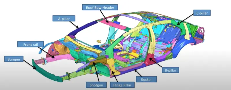
NOMENCLATURE OF THE COMPONENT
PROCEDURE PERFORMING THE CRASH IN RADIOSS
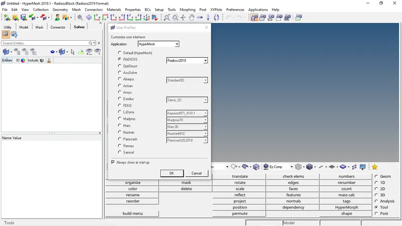
- Open the hypermesh software and keep radioss as the profile
- Then after we need to import the model
- After that, we need to export the file to radioss and import to hyper crash
- By going to applications we can open hypercrash
- And we need to check the model by the model checker
- If any warning arises we need to rectify them and we can neglect some warnings
- And then we need to adjust the center of gravity of the component
- After then we need to create a rigid wall and then we need to velocity to the entire component
- Then we need to make self contact interface to the entire car component
- After completion of all those steps, we need to create a section to observe the distribution of the force
- Then we need to give the timestep and runtime to the solver
- We ask the solver to give an output request by creating the control cards and output request
MODEL SETUP
- IMPORT THE MODEL
Goto import and then select the file to import and select import
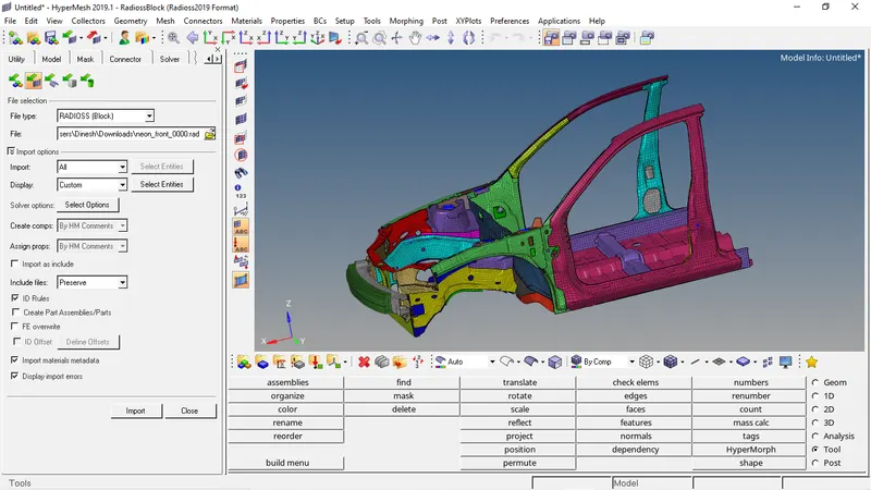
- Then we need to export the file to hypercrash and open it in hypercrash
- Before starting hypercrash GUI will ask about unit set the units to kg mm ms
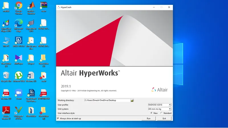
- After selecting the units we need to drag and drop the file location directly to the GUI
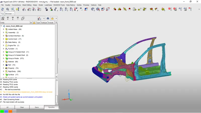
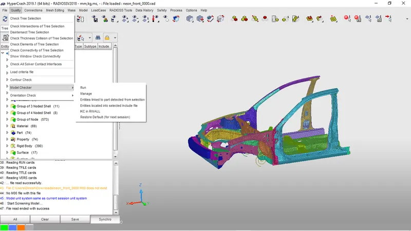
- We need to use model-checker and rectify the error
- By going to quality and selecting model-checker and by run we can check the warnings and errors in the model
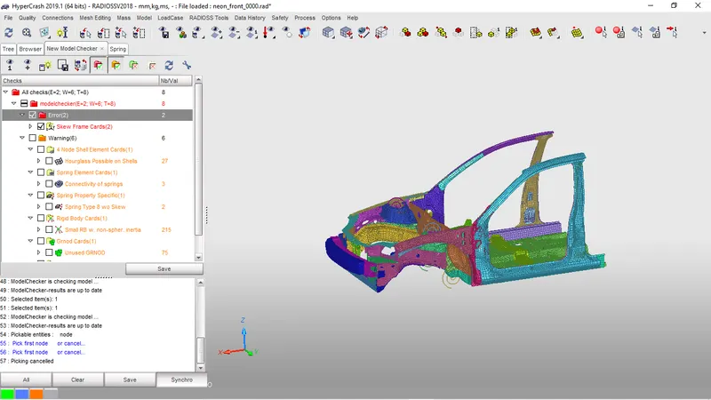
- These errors are major we can neglect them
BALANCING CENTRE OF GRAVITY
component before balancing center of gravity
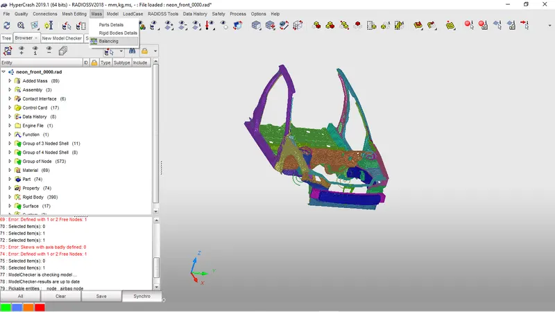
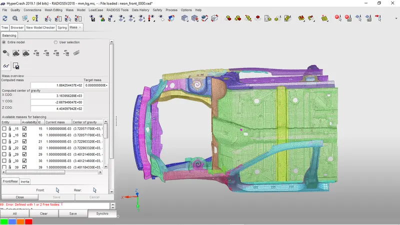
- To bring the center of gravity to the center we need to add mass additionally
- To add mass we need to go to load case and select add mass
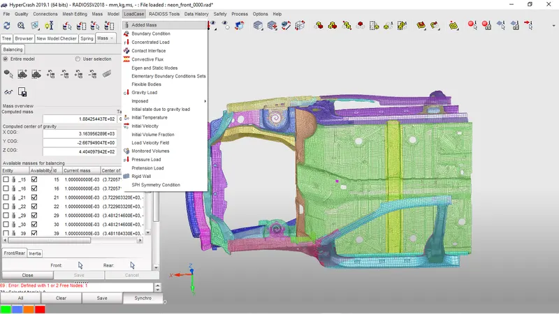
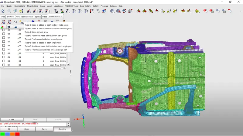
- To add mass there are different types majorly we use type 0, type 1, type 3
- Type 0 and Type 3 will distribute the mass along part what we had mentioned
- Type 1 will multiply the nodes into giving weight every node carries given weight
- The target mass for adding is 700kg
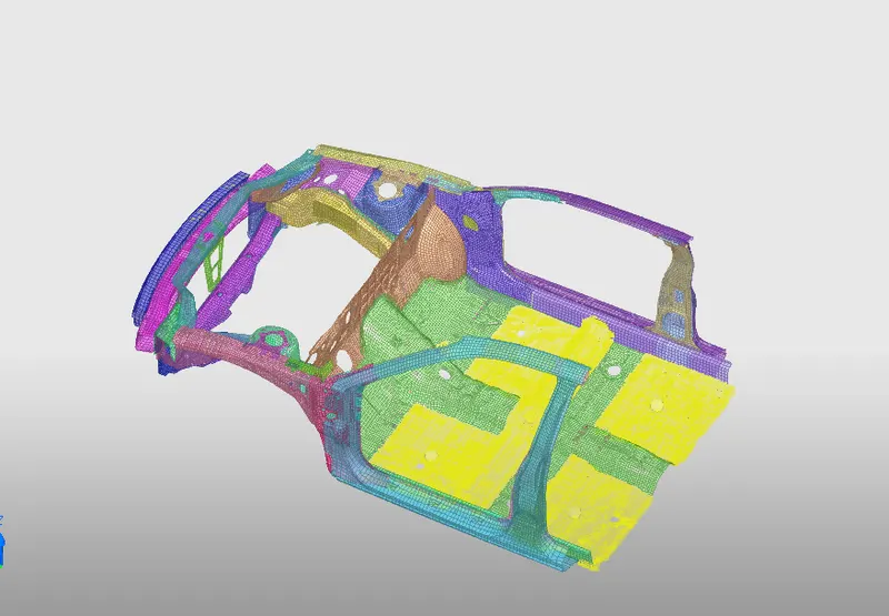
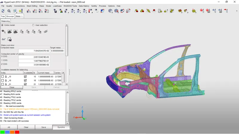
- After balancing the center of gravity
CREATING THE RIGID WALL
- Open browser right-click on the empty space then it will ask to create new and select rigid wall
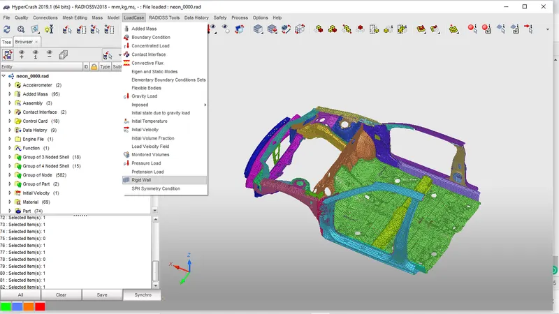
- After selecting the rigid wall it will ask for a point select the point that rigid wall must be placed correctly
- Select the center node at the upfront of the model
- And specify the normal and select create
- And we need to change sliding to sliding with friction and give friction as .2.
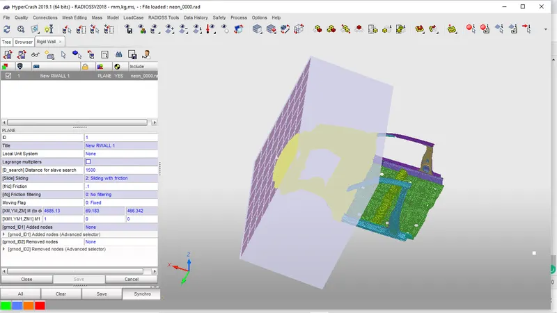
- The major thing here is to set the value of the search
- As this part of an experiment, we had created 3 models considering search =0,1500, entire component
- If dsearch is zero the no collision will take place with rigid wall
- But by considering search 1500 or entries component the results are the same but search for the entire component will take high computational time
- Dsearch will take the nodes as a slave up to that distance specified
INITIAL VELOCITY
- To consider the crash we need to move the rigid wall to car or car to rigid wall
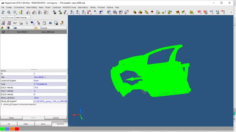
- We need to study the car we will consider the car must move with a velocity
- To assign velocity to car we need to select load case and select initial velocity
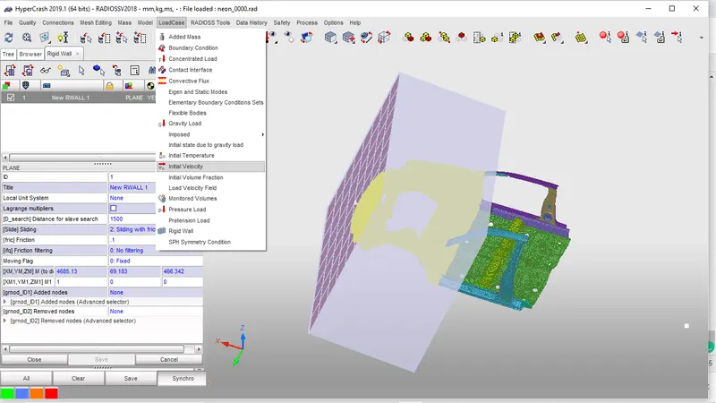
- After selecting it will ask about the node we need to select all node to move the component
- We need to specify the direction of velocity and mention it carefully with respect to the units
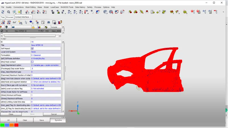
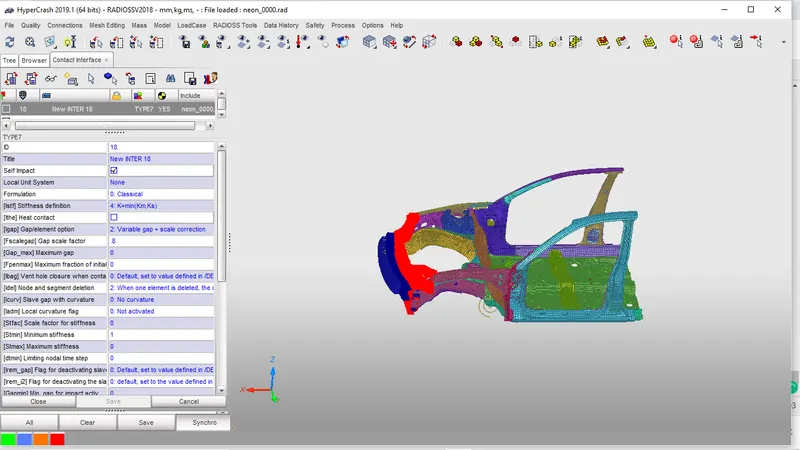
CREATING CONTACT INTERFACE
- As we know that we need to create a master and slave for a contact
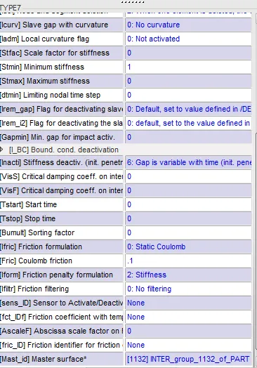
- But now we are giving the self contact entire surface by using type 7 interface
- The properties must be given which are recommended
- For creating the interface we need to select contact interface from load cases
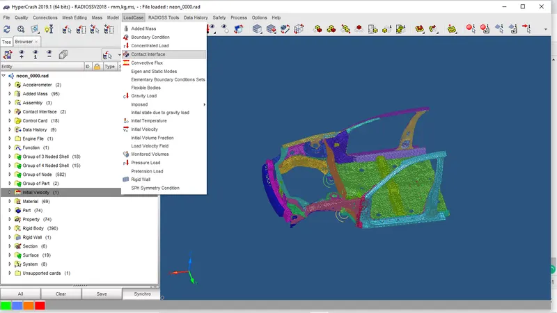
- In this, we need to create 2 interfaces 1 for self contact and others for measuring axial force we need to specify a contact between the bumper and light housing
CROSS SECTIONS
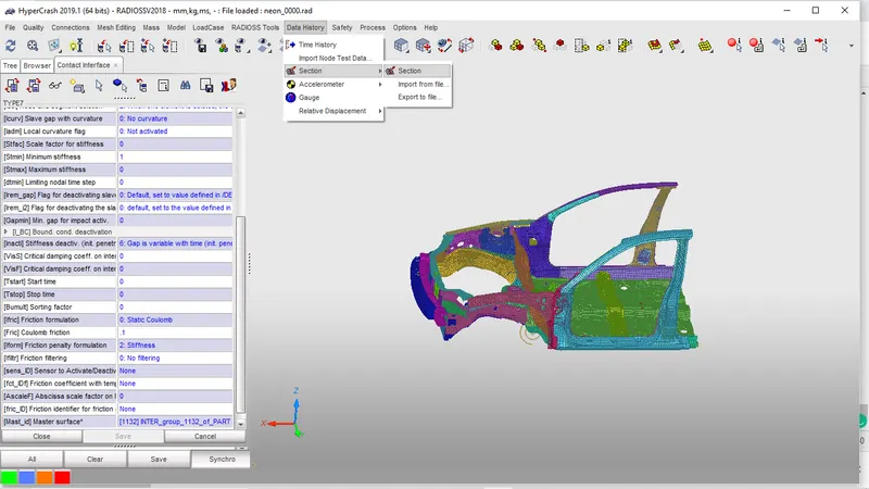
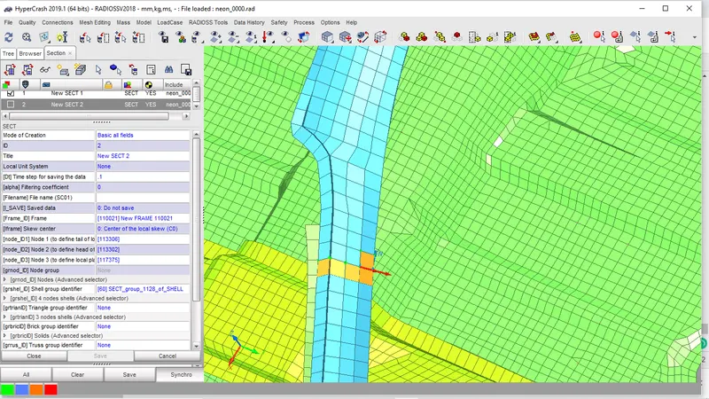
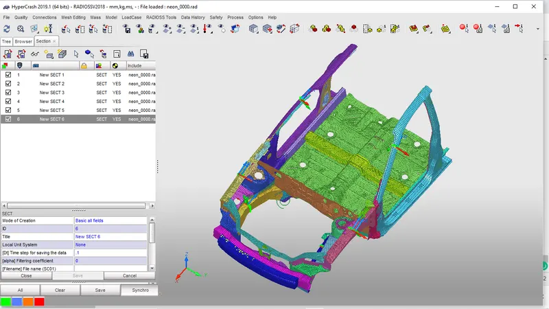
- Crossection needs to observe the distribution of the forces in different component
- As of now, we need to see the sectional forces at a pillar, shotgun, rail
- To create a cross section we need goto data history and we need to select the sections
- After that, we need to specify normal force opposite to the direction of the velocity
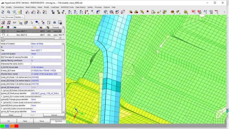
- As to create sections we need to specify the frame
- the frame is used t specify the local axis of the section where the calculation force is done with respect to the local axis
- To create a frame we need to specify the nodes N1, N2, N3
- For MOV N1, N2 represents the origin, x-axis and N3 represents XY plane
- For MOV2 N1, N2 represents the origin, z-axis and N3 represents xz plane
- After specifying the normal axis we need to select some group of the element to create a section
- If any trias are there we need to select shell 3n and select trais
OUTPUT REQUESTS
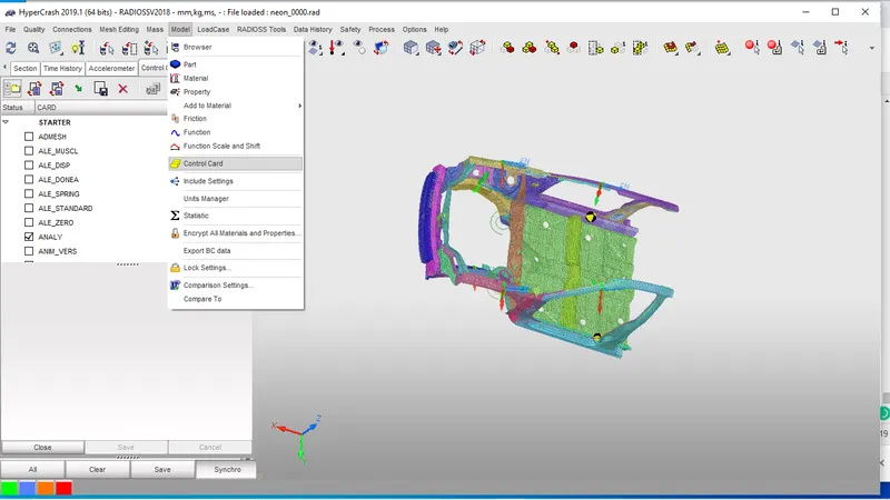
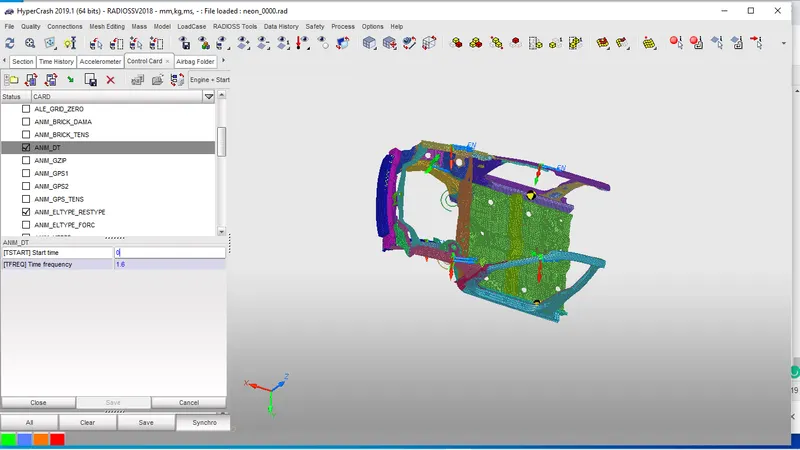
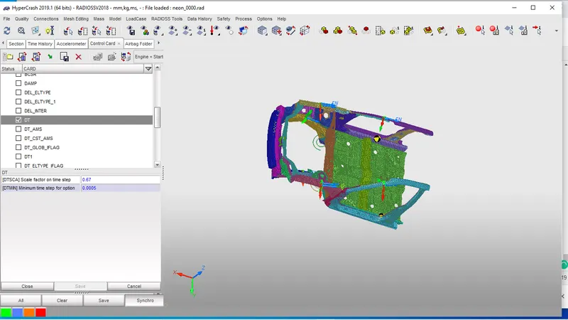
- We need specifiy the time step=0.0005and t frequency=1.6
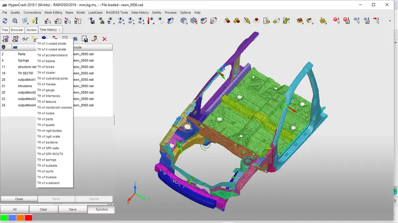
- we need to creat extra file in solver of TH by selecting sectio and select all six sections
- Create TH for node and select the node for finding intrusion
- Creating TH for interface and the two contact interfaces specified
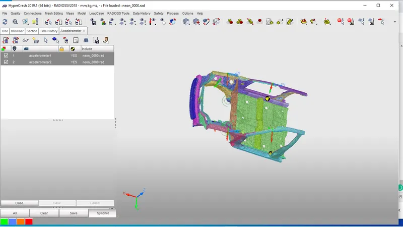
- We nee create accelerometer at B-pillar and we call for output request by selecting the TH accel
RUN THE STIMULATION
- We cannot run stimulation in hypermesh
- So, we need to export to radioss
- After that, we need to go to analysis and click on radioss
- Select the file location and specify -one step then it will give starter out file
- After getting the starter out file check any warning or error is present
- If present rectify them and write -nt 4 in the command bar and run the stimulation
RESULT AND ANALYSIS
- As per given output requests we need to see energy error and mass error
- The mass error comes we impose the time step
- The mass error must not cross 2% and the energy error must greater than -15%
- If the mass increases the K.E increases the internal error will increase unconditionally
CYCLE TIME TIME-STEP ELEMENT ERROR I-ENERGY K-ENERGY T K-ENERGY R EXT-WORK MAS.ERR
159900 79.95 0.5000E-03 NODE 174393 -1.6% 0.4505E+05 0.3661E+05 4.805 -2094. 0.1215E-02
STARTER RUNTIME = 9.48s (00:00:09)
# 001 ENGINE RUNTIME = 13091.65s (03:38:11)
------------------------------
STARTER+ENGINE RUNTIME = 13101.14s (03:38:21)
TOTAL NUMBER OF CYCLES: 160001
- Here the energy error is -1.6% and mass 0.12%
STIMULATION

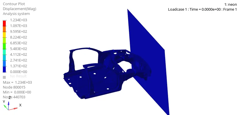
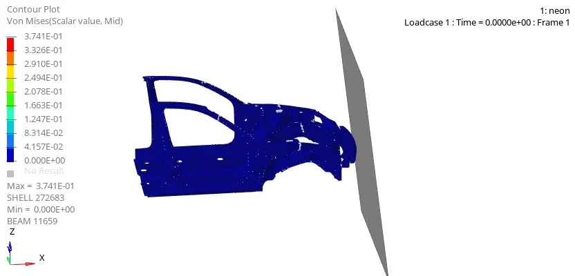
EXPLANATION:-
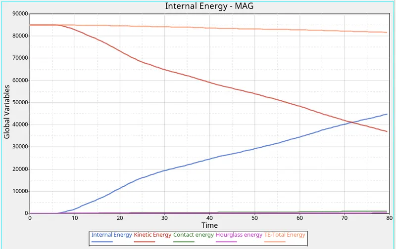
- As we can see that the contact between wall and vehicles is started at 8.8 ms
- From that, the K.E is decreasing gradually so that while impact takes place, then it starts to deform so that the strain energy will be increasing
- The total energy of the system is balanced but there are some crests because of the contact energy
- In this hourglass, energy is constant due to Qeph element formulation
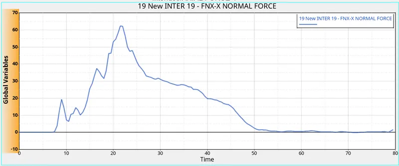
- Axial force occurred at the bumper as we can see after 8.8ms there is a sudden rise in the force of the bumper
- That means after contact the forces are distributing directly to light housing, rails, etc
- The peak force is at 22ms of 70kN/mm^2 that was the highest force will be distributed throughout the component
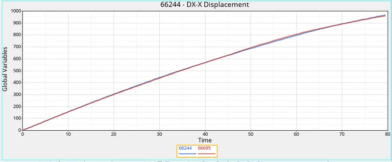
- As of stimulation run, we can see that the displacement is increasing with respective time
- Therefore the force is directly distributing to the driver legs that mean it is not safe for the drive at brake pedal
- It will injure with respective to the velocity of the vehicle
- The maximum displacement of the vehicles is 1000mm
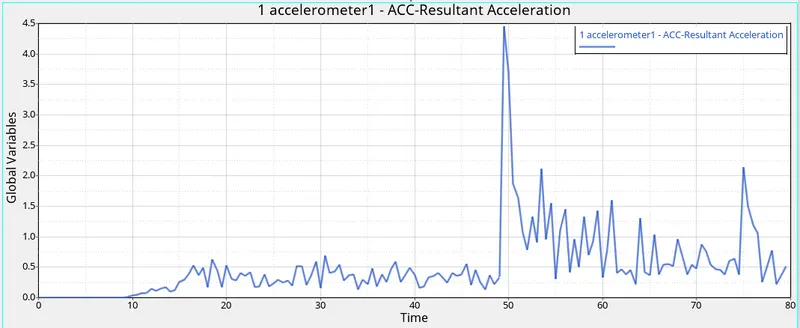
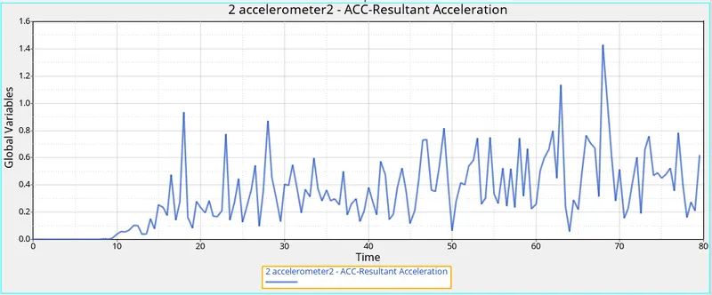
- As we kept the sensors in the base of b pillar so see that acceleration of the vehicle
- As we can see the right side accelerometer is showing less acceleration up to 48ms then after the acceleration increased suddenly
- so that people will have high damage with respect to the left side passenger
- The left side accelerometer is constants that means the force is distributed properly and we can see the peal acceleration is at 1.4 mm/ms^2
- But the peak acceleration of the right side b pillar is about 4.5mm/ms^2
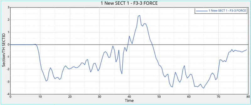
- As the peak force distributed for A-pillar left is 2.5kN/mm^2
- And we can see the force are been in a negative direction that means component resist the force that produces due to impact
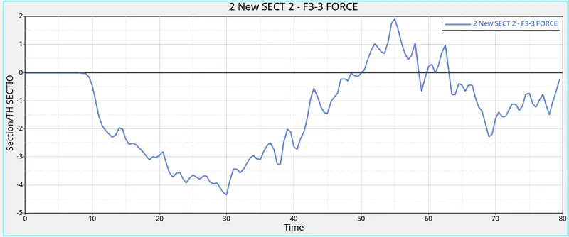
- As the peak force distributed for A-pillar right is 2 kN/mm^2
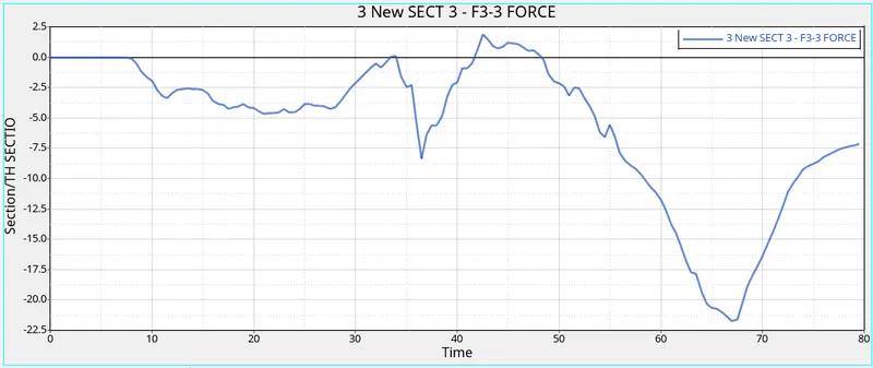
- As the peak force distributed for shotgun left is -22.5 kN/mm^2
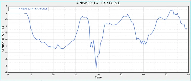
- As the peak force distributed for the shotgun right is -8 kN/mm^2
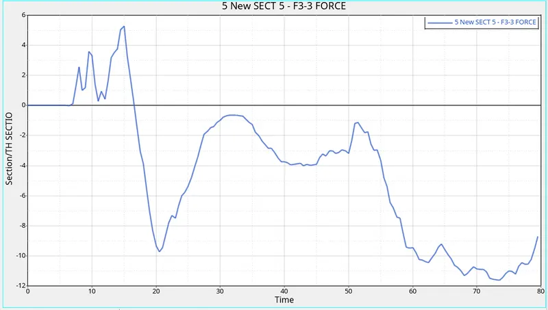
- As the peak force distributed for shotgun left is -10 kN/mm^2
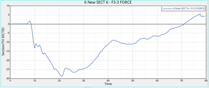
- As the peak force distributed for shotgun left is -25 kN/mm^2
- As we can see that the axial force distributed to the component is 70kN/mm^2
- From that force is transferred to the rail which absorbs -25kN/mm2 by right and -10 kN/mm^2
- And other force is taken by the shotgun is -8KN/mm^2 and by right -22.5kN/mm^2
- The force that reached the A-pillar is -3kn/mm^2 and by right -4.5KN/mm^2
- From the above answer that I can say that the right compartment of the car exerting hight force so that people might have high injuries
- As of the force is the distribution as original component as such
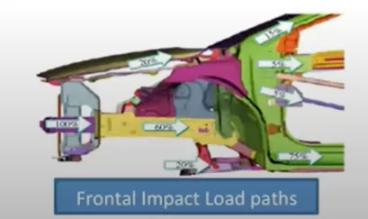
- But as we can see the force absorb is 100% the shotgun take 35% of the force and rail to take about 40%
- And remaining is sent to the base
- But after that only 7% of force are distributed so that all force that will be driven to a cabin
- So that the car fails for frontal impact test
CONCLUSION:
- Understood how to perform crash analysis
- Understood and performed the crash analysis to car component given
- Created section to observe the distribution of the forces
- Understood how to apply output request from the solver
- Understood how to analyze the graph of crash stimulation
- Understood the concept of mass scaliling and up to which sort it must use