Assignment 5-RADIOSS Interfaces & Study of Effect of Notches Challenge
AIM: The main is to create the mesh and give the connection and run the simulation.
OBJETIVE:
- Create the mesh for bumper assembly,mesh size should be 6mm.
- Run the crash tube model as it is.
- Change the Inacti=6 and run.
- Create the type 11 contact and run.
- Remove both notches and remove boundary condition on rigid body node then run.
- Create a new notch in the middle ,select the whole section and run.
- Create a new notch with nodes only from opposing 2 faces and run.
Note:
- Plot RWALL forces ,contact forces,internal energy and Create TH/PART for all parts and compare results for all cases.
- Comment your thought on why there is a change in the internal energies.
- How does the notch affect the results?
- Plot energies and note any difference.
METHODLOGY for Model 1:
- Open the model.
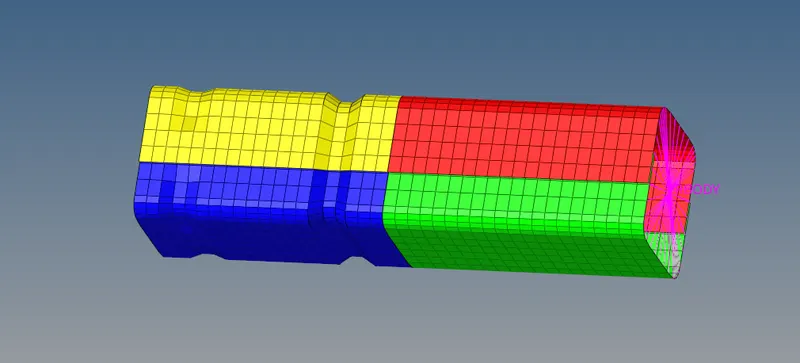
- create the mesh
- Give quality parameters
- Give the onnections.
METHODLOGY for Model 2:
- Opening the file
- Run the simulation
- comparing the cases.
Procedure for model 1:
- Importing the given model into the GUI.
- For importing the given model go to File>import>import the model>clcik on import>the model is imported into the GUI.
procedure for meshing the given model:
- For meshing the given model we should have to give the target element length as 6 to the model. By going to the preferences>>criteria menu settings>Target element 6>click on ok.
- The Critera is gievn to the model.
- For performing the auto meshing we should go to the 2D panel>auto mesh>select the surface >Displayed>element sized>mixed>click on the Mesh.
Procedure for setting of the connections.
- To provide the connection to the given model we should go to 1D panel bar.
- Go to 1D panel>connection>spot>select the location of the nodel path>select the nodes>give the spacing as 6>select the component>give the tolerance as 6>Type as weld>create.
- The connection on the 2 different parts which are parllel to each other will be given connection.
Case 1:
- Imporitng the given model.
- After importing the given model we should save the model.
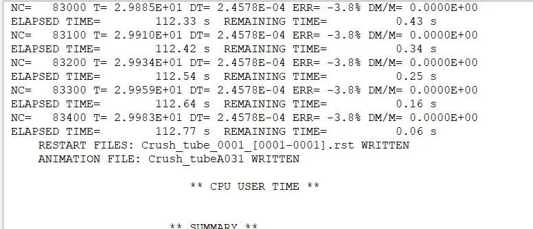
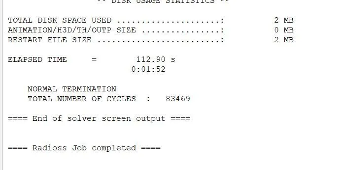
- We should have the run the simulation as it is without any changing the values Analysis>Radioos>Select the .h3d file>-nt 4>Cilck on apply.
- So that the simulation will be running takes place and we can obtain the errors and elapsed time and time in sec.
- so that the simulation is taken in the model.
Analysis by Radioos:
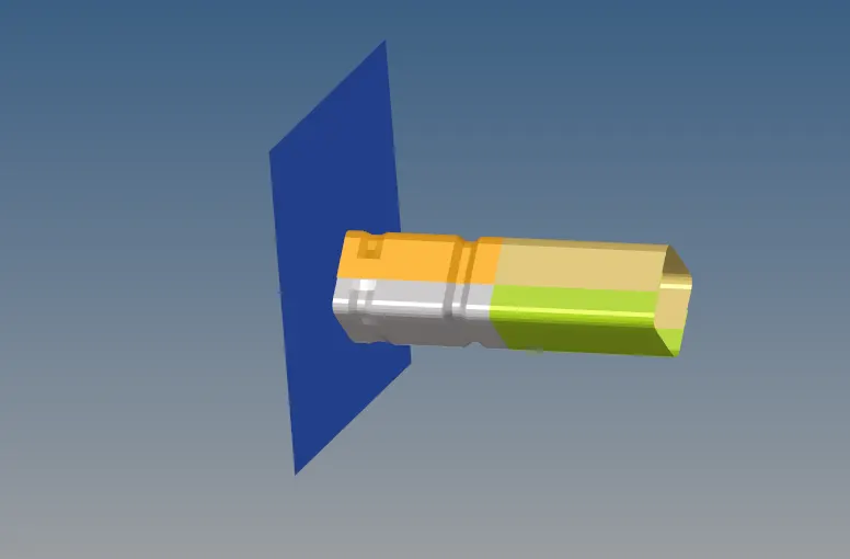
Model in the Hyper view:
-
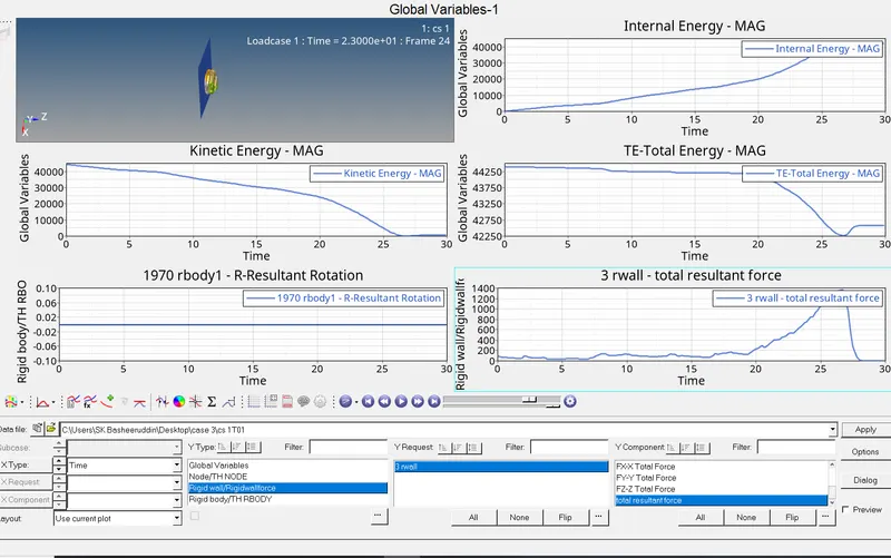
- Graphs in the Hypergraph
-
- Case 2:
- Import the given model by File>Import>solver deck>click on import.
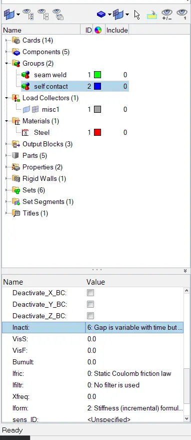
- After importing the model we should change the In acti to 6 it will aviliable in the Model Browser>Gropus>change the value.
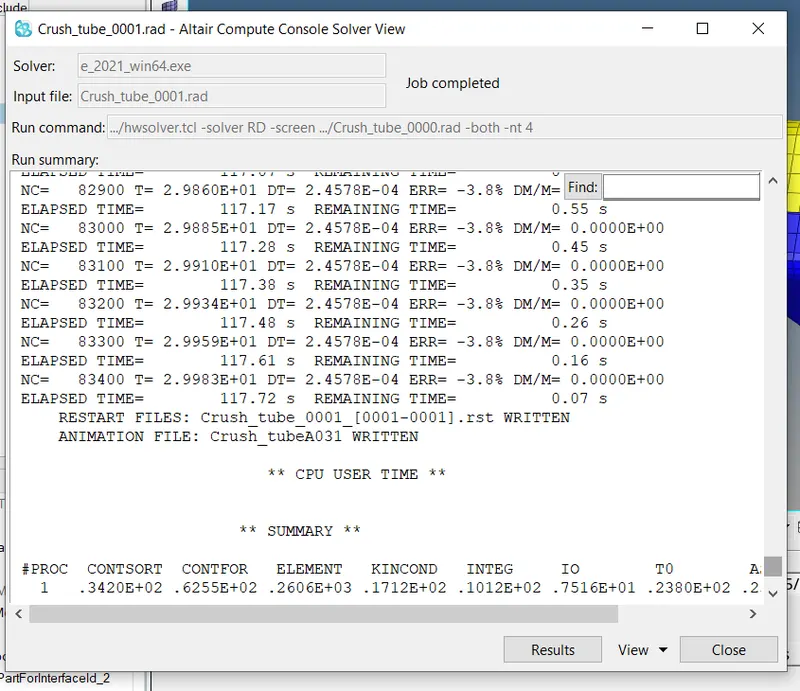
- We should have the run the simulation by Analysis>Radioos>Select the .h3d file>-nt 4>Cilck on apply.
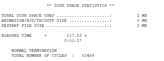
- So that the simulation will be running takes place and we can obtain the errors and elapsed time and time in sec.
- so that the simulation is taken in the model.
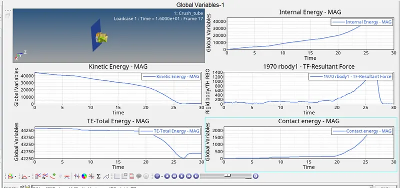
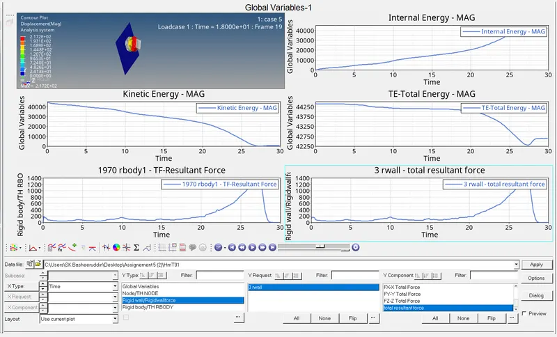
- We should have to plot the graph by going to Hyper graph>plot the graph of internal energy,Kinetic energy.Total energy,Total resulant time.
-
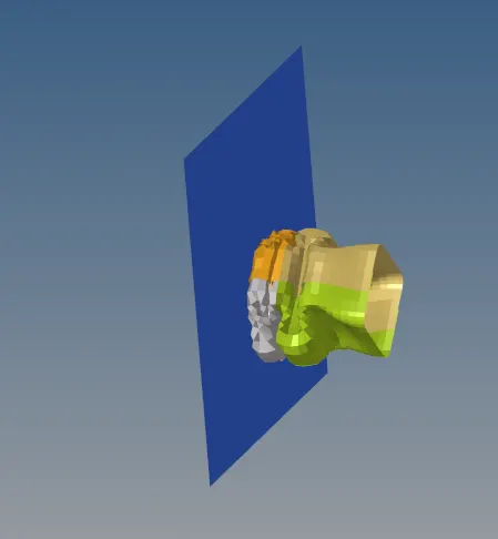
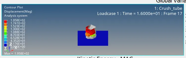
Simulation on the Radioos
Model in the Hyper view
Model in the Hyper Graph
Case 3:
- Import the given model by File>Import>solver deck>click on import.
- We should have to create a new interferance by go to model browser>Right click on the group>create new type >click on ok.
- After that we should assign the some values to the Type 11 model
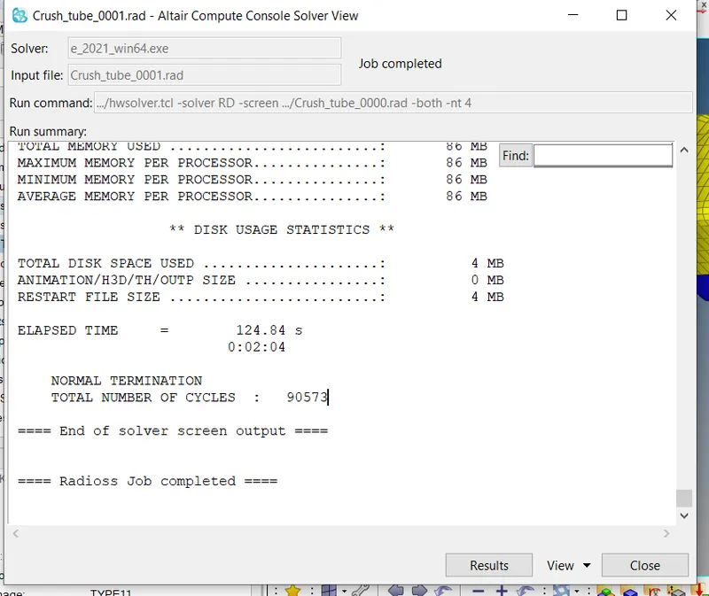
- We should have the run the simulation by Analysis>Radioos>Select the .h3d file>-nt 4>Cilck on apply.
- So that the simulation will be running takes place and we can obtain the errors and elapsed time and time in sec.
- so that the simulation is taken in the model.
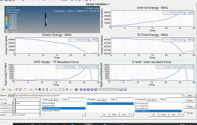
- We should have to plot the graph by going to Hyper graph>plot the graph of internal energy,Kinetic energy.Total energy,Total resulant time.
-
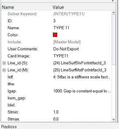
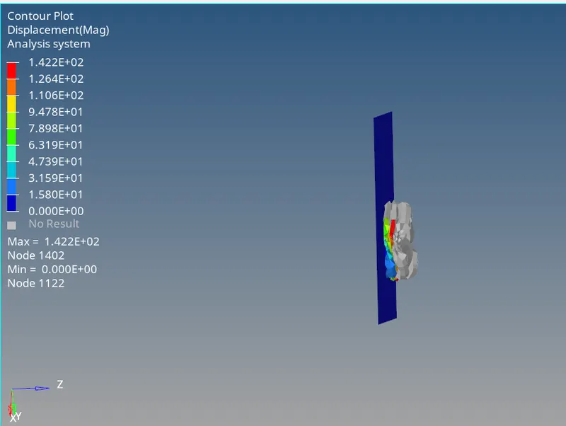
Analysis done in the Radioos
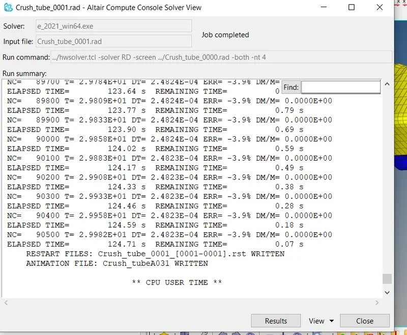
Model in the Hyper view
Model in the Hyper Graph
Case 4:
- Import the given model by File>Import>solver deck>click on import.
- We should have to delete the given notch and create plain surface on the model.
- To create the plain surface >Geomentry>node edit>align>nodes will be align in the model.
- We should have the run the simulation by Analysis>Radioos>Select the .h3d file>-nt 4>Cilck on apply.
- So that the simulation will be running takes place and we can obtain the errors and elapsed time and time in sec.
- so that the simulation is taken in the model.
- We should have to plot the graph by going to Hyper graph>plot the graph of internal energy,Kinetic energy.Total energy,Total resulant time.
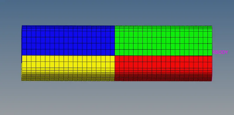
Analysis done on the Radioos
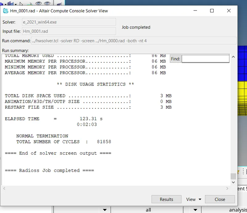
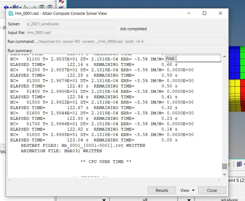
Model in the Hyper view
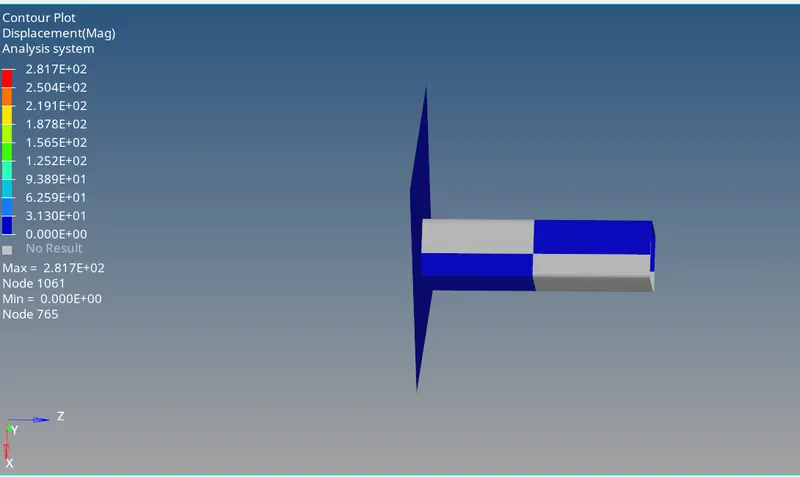
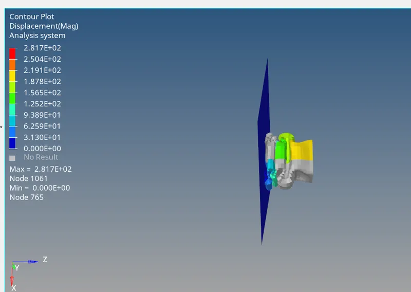
Model in the Hyper graph
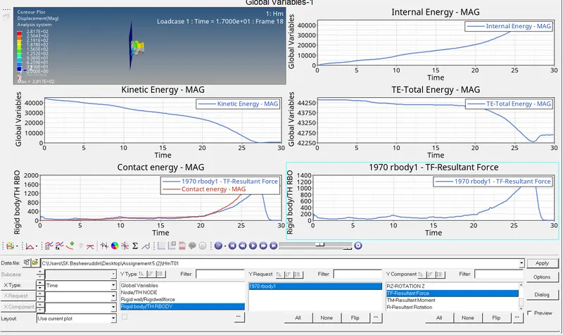
Case 5:
- Import the given model by File>Import>solver deck>click on import.
- We should have to create a notch on the given plain surface.
- For that we should have to go to Translate >give the direction >with the maginitude of 4.
- We should have the run the simulation by Analysis>Radioos>Select the .h3d file>-nt 4>Cilck on apply.
- So that the simulation will be running takes place and we can obtain the errors and elapsed time and time in sec.
- so that the simulation is taken in the model.
- We should have to plot the graph by going to Hyper graph>plot the graph of internal energy,Kinetic energy.Total energy,Total resulant time.
-
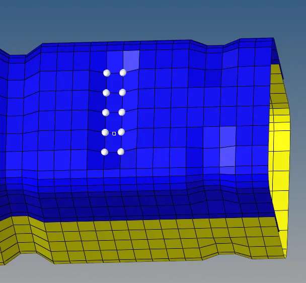
Analysis done on the Radioos
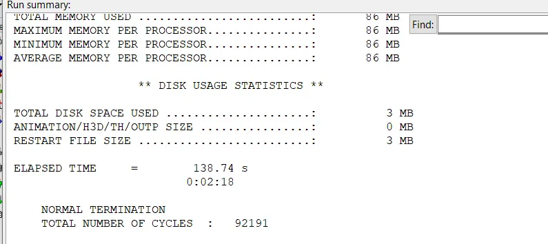
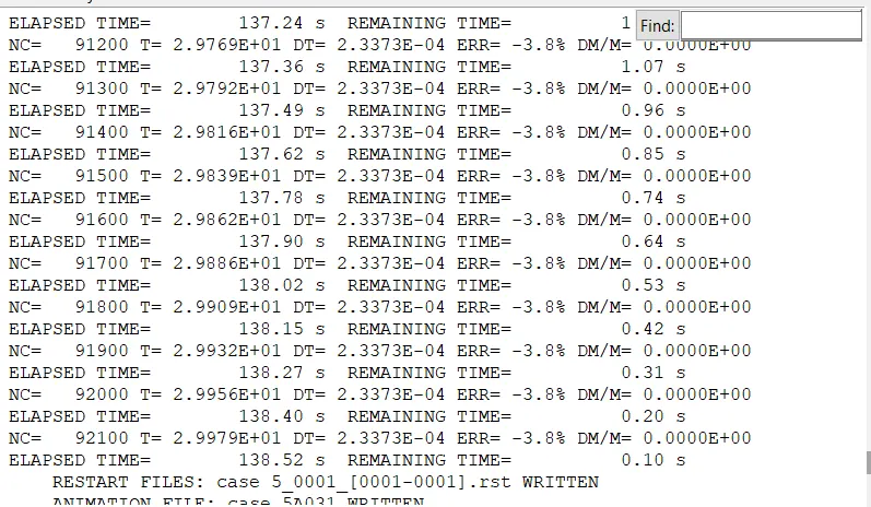
Model in the Hyper view
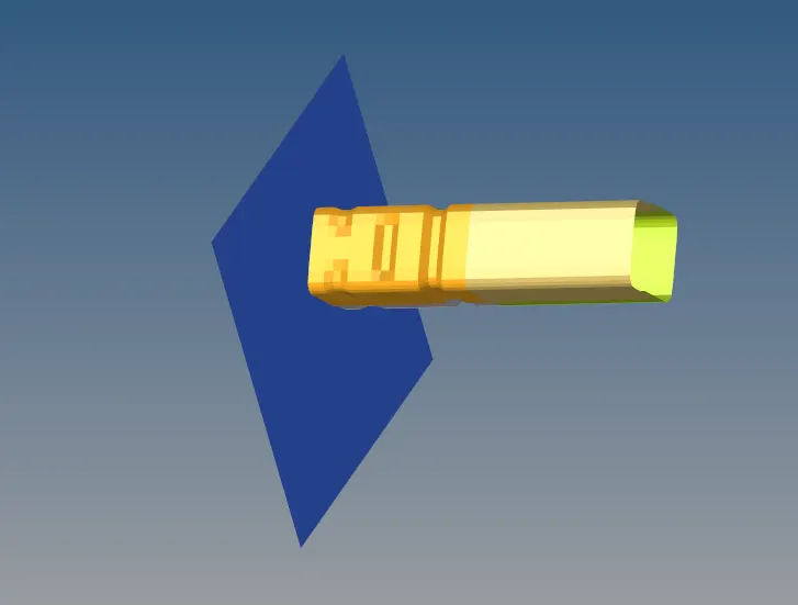
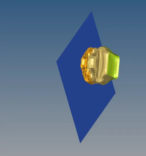
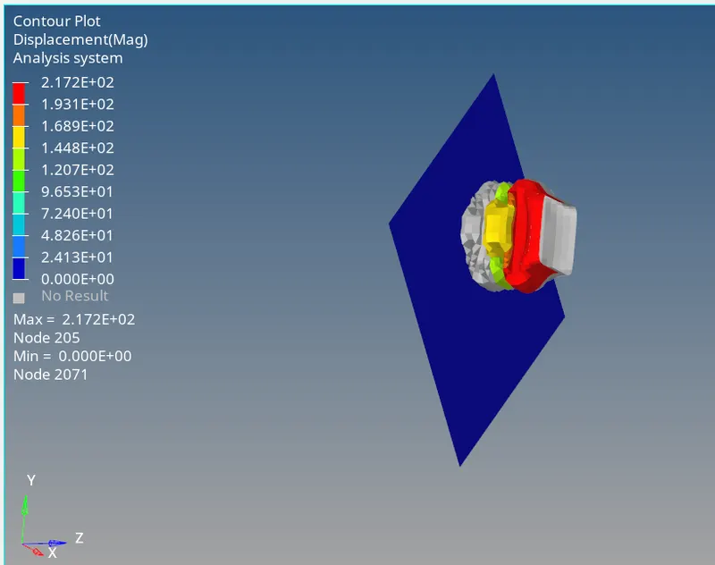
Model in tHE Hyper Graph
Case 6:
- Import the given model by File>Import>solver deck>click on import.
- We should have to create a notch on the given plain surface.
- For that we should have to go to Translate in the opposite direction>give the direction >with the maginitude of 4.
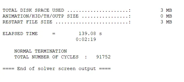
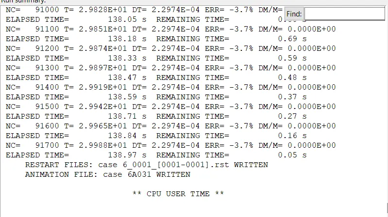
- We should have the run the simulation by Analysis>Radioos>Select the .h3d file>-nt 4>Cilck on apply.
- So that the simulation will be running takes place and we can obtain the errors and elapsed time and time in sec.
- so that the simulation is taken in the model.
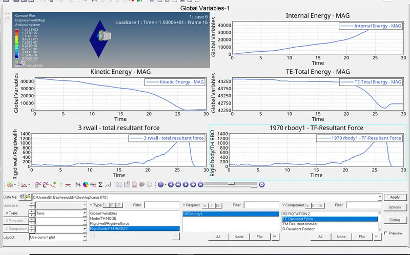
- We should have to plot the graph by going to Hyper graph>plot the graph of internal energy,Kinetic energy.Total energy,Total resulant time.
-
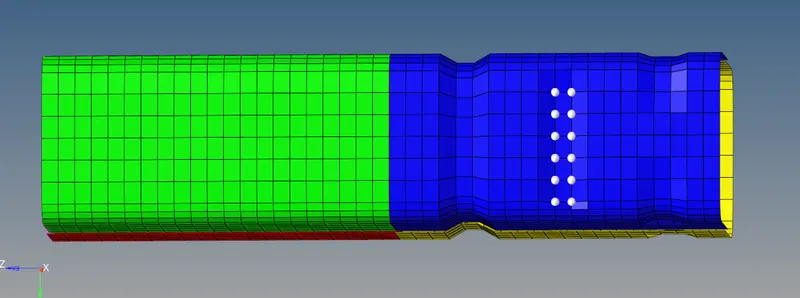
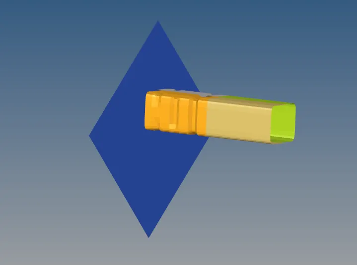
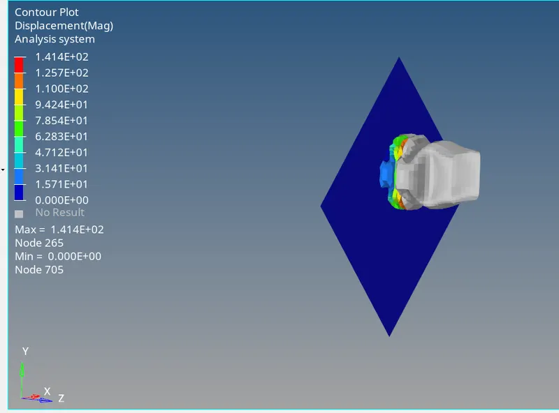
Analysis done in the Radioos
Model in the Hyper view
Model in the Hyper Graph
Type 7:
Type 7 is a Node to surface type of contact.
A general-purpose interface and can simulate all types of impact between a set of nodes and a master surface.
It is a Non-Oriented and Slave nodes can belong to the master surface and hence, auto impact possible.
Automatic Nodes to surface contact interface using the penalty method with variable stiffness.
Type 11:
The Type 11 will be an Edge to Edge type of contact.
In the case of edges crossing, the Type 11 interface can be added to capture the physics correctly.
It is defined by identifying master and slave lines/edges.
It works similarly in terms of Type 7 in terms of
Penalty Formation.
Gap Definition.
Search method.
Istf:
It is a Gap for stiffness definition; it is the Interface stiffness which is the maximum of the master and slave stiffness.
Igap:
It is a gap/element option flag. The gap between the master and slave node is not defined in this case.
Idel:
It is the Node and segment deletion flag. The value is set to 0. It is defined as the default values added in the /DEFAULT/INTER/TYPE11
Stmin:
It is the minimum stiffness value and can be used only if the Istf is not equal to 1.
Stmax:
It is the maximum stiffness value and can be used only if the Istf is not equal to 1.
Iform:
It is the Friction penalty formulation type. In this case, it is set to 0 which takes the value defined in the /DEFAULT/INTER/TYPE11.
Fric:
It is a Coulomb Friction and it refers to a simple model of dry friction that is fairly accurate empirically. Specifically, it is a model that helps predict the direction and magnitude of the friction force between two bodies with dry surfaces in contact.
Gapmin:
It is the minimum gap for the impact to activate.
Inacti:
It is the option to deactivate the stiffness. In this case, the Gap is variable with time, but initial penetration is computed as (the node is slightly de-penetrated)
There are many this learned in this project.
Learned what the flags inside the Groups mean and how they affect the model.
Learned how the notch elements change the effect of the deformation.
Learned to use the interfaces better.