Assignment 5-RADIOSS Interfaces & Study of Effect of Notches Challenge
OBJECTIVE:
- Create the mesh for bumper assembly, mesh size should be 6mm. 2. Run the Crash tube model with 6 different cases as given below and compare.
- Run the crash tube model as it is. Change the Inacti=6 and run.
- Create the type 11 contact and run.
- Remove both notches and remove boundary condition on rigid body node then run.
- Create a new notch in the middle, select the whole section and run.
- Create a new notch with nodes only from opposing 2 faces and run.
1. MESH THE GIVEN BUMPER MODEL
Procedure:
Model 1:
Meshing the given model(Bumper):-
- select the user profile
Import the hm model of bumper system
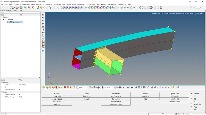
- The next step is to view the component by a topo. in order to check for geometrical errors. After switching it to the topo, the geometry in the graphical display
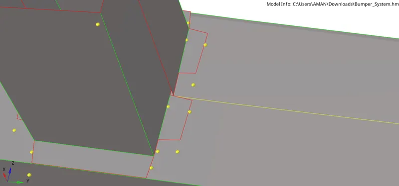
Geometry clean up:
we can see in the figure below there are surfaces detaches from the crash box
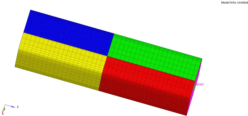
we can fix this geometrical errors using tools in quickedit panel, Geometry Quick edit go to project points and project points from the separated surface to the free edge of main surface and use replace point option to make connection between surfaces, and bumper beam mid surface is not intersected to the upper and lower surfaces.
we can fix this using Geometry -> surface edit -> trim with surfs/planes -> selfintersecting surfaces ,select both surfaces and trim


Meshing:-
- Before meshing, the parameters are element size is 6mm in the auto mesh panel should be selected. And then by selecting the surfaces by clicking on mesh, the mesh will be generated. go to 2D -> AutoMesh
- After meshing the entire component, it appears as
CHECK FOR FREE EDGES:
- we have to check for free edges (red lines) in the component.
- Edges Tool will help us find this error:
- Tool >» Edges [Shift + F3] » Elem's » Select by box selection >> Find edges
- If free edges are present, connectivity won't be established between the surfaces.
- As a result, when force is applied on any surface it won't be distributed to the neighboring surface due to a connectivity issue.
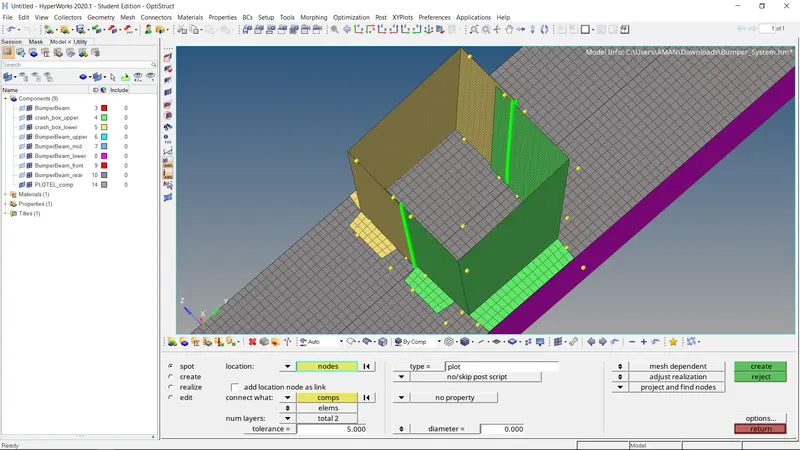
we can create 1d connections between crashbox and bumber system, go to 1D -> connectors -> spot
select the nodes we wanted to create connections between and select the 2 cpmponents
After creating spot weld connections between crashbox and bumber system
Now we can reflect the half part to get the complete bumber system model, goto Tools -> Reflect,
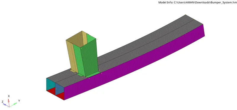
Complete Meshed bumper system:
Running Simulations on the crush tube
There are 6 cases to be carried out and all of them have mostly common procedures, except the interface/model changes, which are outlined as follows:
- The crush tube model will be imported into Hyperworks vi the 'import solver deck' option in the upper toolbar, or through File > Import > Solver Deck.
- As per the given requirements, the changes shall be made in this step, either through the model browser in Hyperworks, or by switching to Hypercrash via Applications > Hypercrash in the toolbar. Specific instructions will be explained within each case.
Accessing Hypercrash:
- After the changes are made, we can move to the analysis section in Hyperworks and select 'Radioss' (if Hypercrash was used to make changes, the model needs to be exported first through File > Export in Hypercrash. Then it needs to be imported again in Hyperworks, after which the radioss tool can be accessed).
- Before carrying out radioss analysis, we can go ahead and create the TH/PART. This will only need to be done once, for the 1st case, since this will be reflected on the remaining cases since each case will be making use of the starter file from the previous case.
Firstly, we can move to the solver tab. This can be enabled through View> Browsers > Hypermesh > Solver. Then, we simply need to right-click in the solver interface and go to create > TH > PART to create TH/PART.
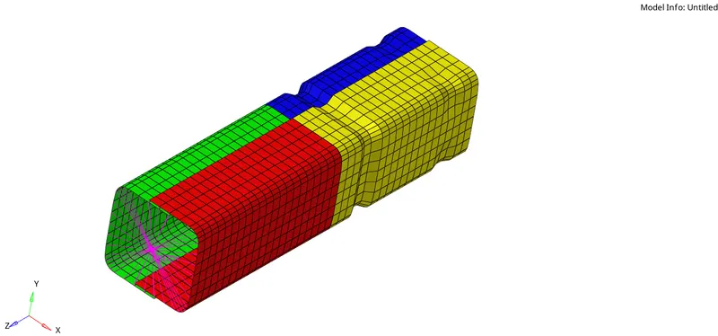

check the model in hypercrash
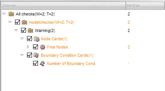
CASE 1
Importing the given crush_tube_o0000.rad file.
Running the analysis as it is without changing any parameter.

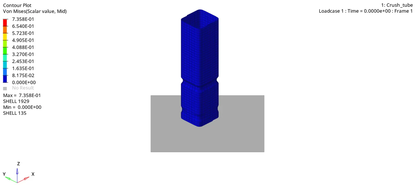
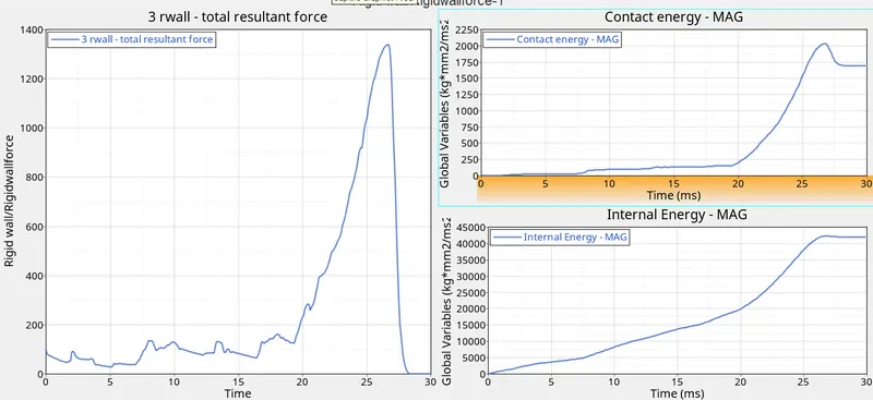
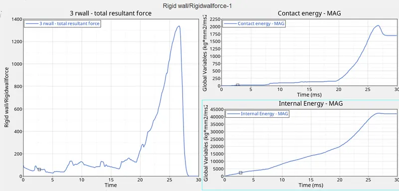
From the graphs we see that rigid wall forces spike when the tube is crushed completely.
Internal energy rises continuously until the tube gets crushed completely
CASE 2
We import the given crush_tube_0000.rad file. Changing the value of inacti=6 in type 7 contact group. Inact is used to auto correct the initial penetrations happening due to the defined contact. Running the analysis and saving it as case2_0000.rad
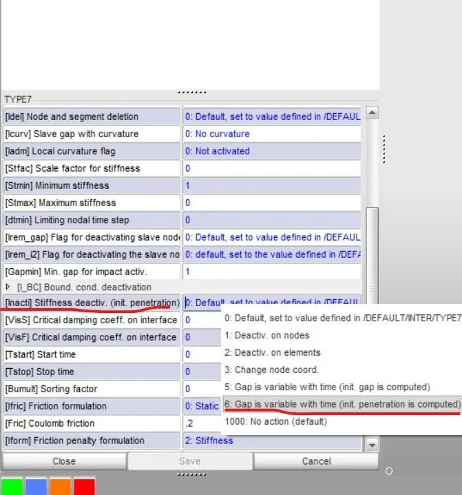
From the above simulation we see that the crushing pattern is similar to the case 1.
By observing the graphs, we see that the graphs are similar to case 1 graphs. This means that there was no initial penetration occurring.
CASE 3
We import the case2_0000.rad file. We now add type 11 contact with the recommended parameters. Type 11 simulates edge to edge contact. This helps in analysing the problem in which the edges interfere with surface without the nodes touching the surface
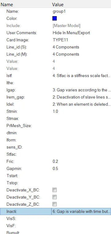
Running the analysis and saving it as case3_000O.rad
From the above gif we observe that the crushing pattern is similar to the previous cases.
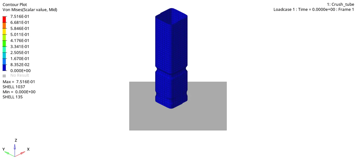
. Also graphs, shown above are also similar to the previous cases. So the type 11 contact isn't helpful in this simulation as there is no edge to surface contact
CASE 4
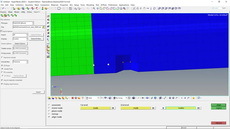
In this case we import the case3_0000.rad. We remove the notches which are present in the model using node edit panel.
Also delete the boundary conditions. Now running the simulation and saving it as case4 0000.rad.
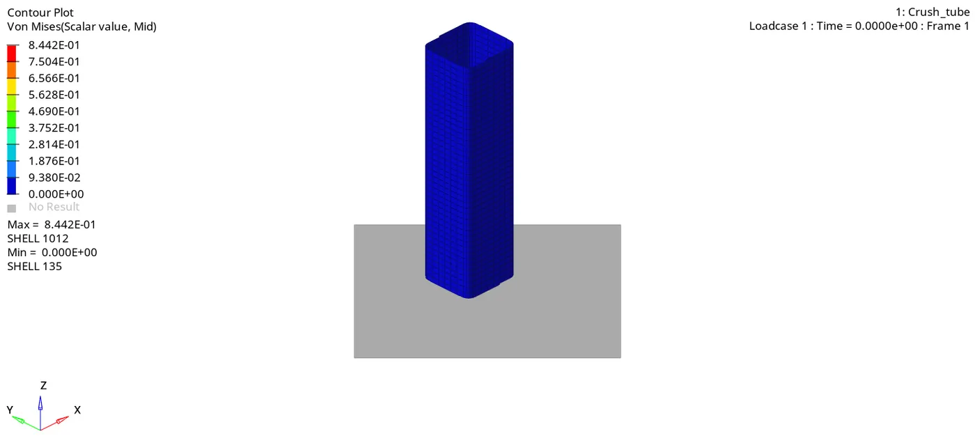
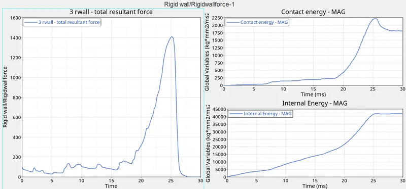
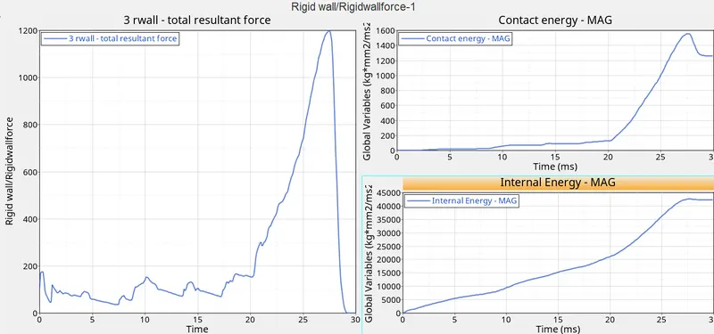
From the above simulation we see that the crushing starts from the bottom layer. The crushing occurs from bottom to top section. We see that rwall forces rise when the crushing starts and then drops down and stays constant for a while and then again starts rising until the whole tube gets crushed. The rwall forces are comparatively cases as in this case. We also observe that towards the end of simulation there is a slight rise in contact which can suggest that after the contact takes place between all the layers, the middle layers and lower layers rebound
CASE 5
We now import the case4_0000.rad file. We create a notch exactly at the middle of the structure using translate panel. We translate the nodes by 2.5 mm.
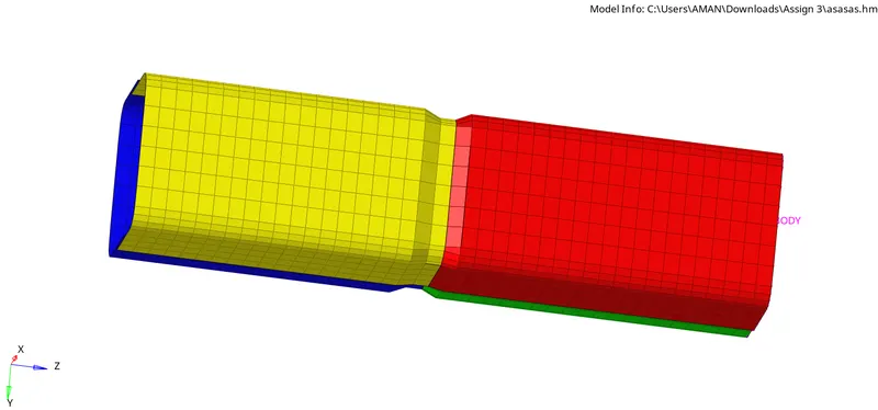
We save the file as case5_0000.rad and the run the simulation. From the above simulation we observe that the crushing starts
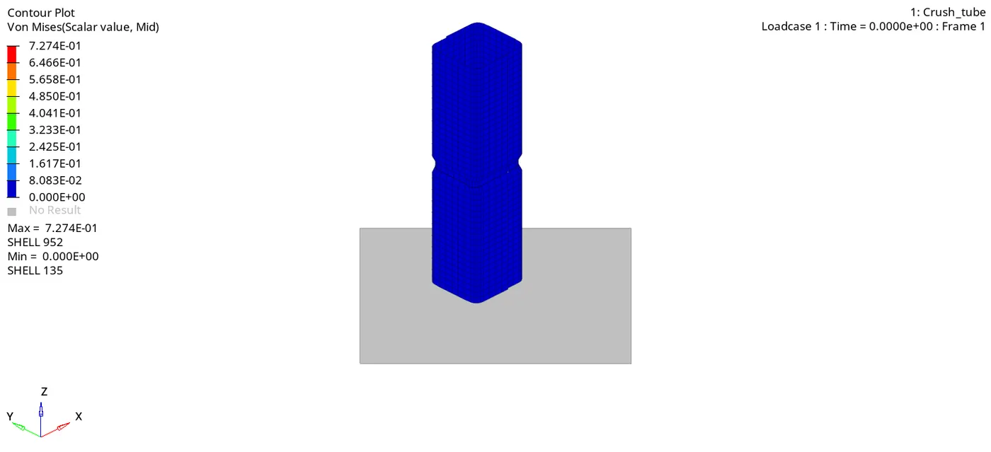
From the above simulation we observe that the crushing starts just below the notch. The rwall forces have a peak at 26ms and then drop down as the tube is crushed completely.
CASE 6
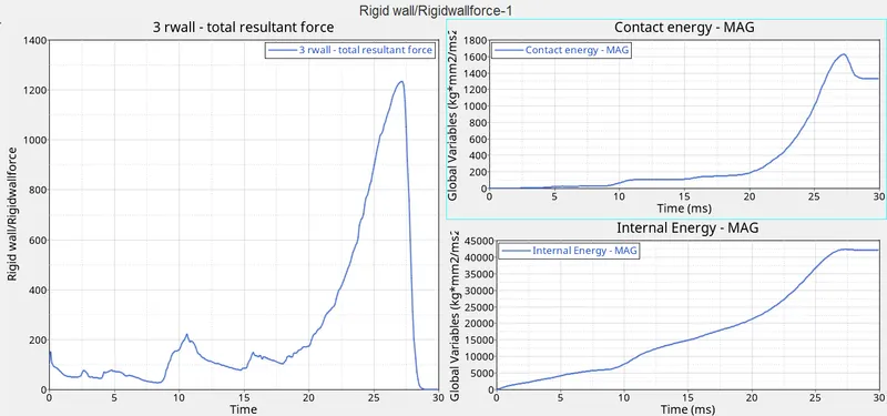
We again import the case case4_0000.rad. We create a notch on opposite faces using translate panel
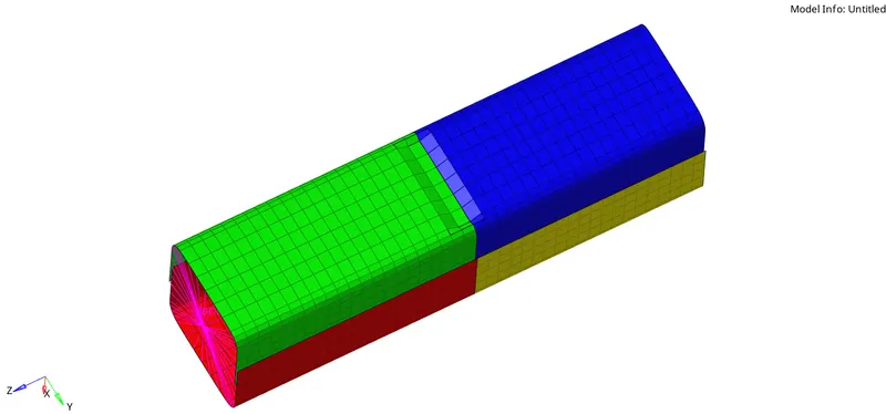
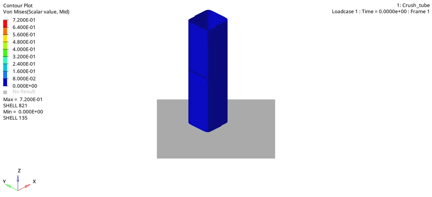
case6_0000.rad and running the analysis. As observed from the simulation, the failure occurs just below the notch. The section below the notch gets deformed first and then the section above the notch deforms.
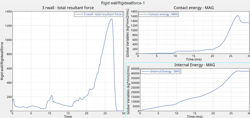
We observe that the rwall forces spike as soon as the contact occurs. The rwall forces peak at about 27ms. Then it drops down as the structure is completely deformed
CONCLUSION:
All the analysis runs had error under-15% and mass error 0%. So the analysis was accepted. I learned what is function of Inacti in interface types. I also learned about type 7 and type 11 interfaces. The notch in structure absorb less forces than the structure without notch. So it is preferable to have no notch in the structure.
DRIVE
https://drive.google.com/file/d/1F8y8JVSdqqigi2wt75jIERKV-MV8FxZS/view?usp=drivesdk