Assignment 5-RADIOSS Interfaces & Study of Effect of Notches Challenge
Aim : Creating mesh on bumper assembly, simulation and analysis of crash tube model.
Questions:
- Create the mesh for bumper assembly,mesh size should be 6mm.
- Run the crash tube model as it is.
- Change the Inacti=6 and run.
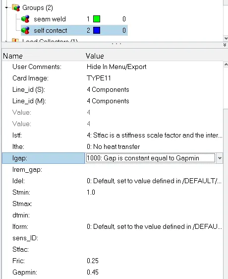
- Create the type 11 contact and run.
- Remove both notches and remove boundary condition on rigid body node then run.
- Create a new notch in the middle ,select the whole section and run.
- Create a new notch with nodes only from opposing 2 faces and run.
Note:
- Plot RWALL forces ,contact forces,internal energy and Create TH/PART for all parts and compare results for all cases.
- Comment your thought on why there is a change in the internal energies.
- How does the notch affect the results?
- Plot energies and note any difference
Obejectives :
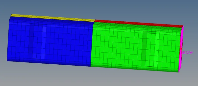
- Bumper assembly
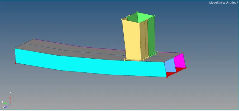
1. Creating mesh for bumper assembly and connecting the whole component with a 2D collector.
- Crash Tube
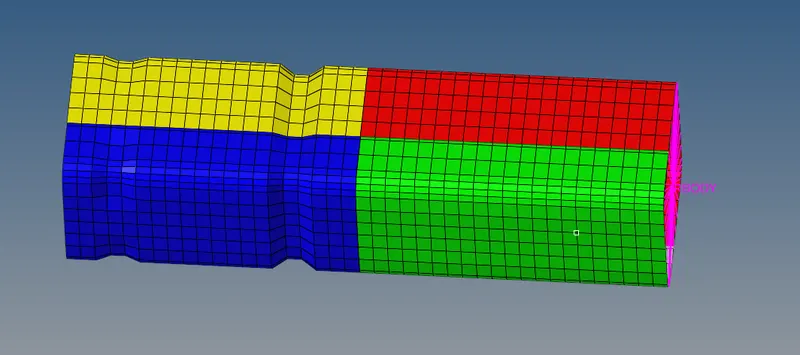
2. Case 1. Simulating and analysing crash tube model as it is given.
Case 2. Simulating and analysing crash tube model after changing Inacti= 6 in groups self contact collector.
Case 3. Simulating and analysing crash tube model after creating type 11 parameters
Case 4. Simulating and analysing crash tube model after removing both notches and boundary conditions
Case 5. Simulating and analysing crash tube model after creating a new notch in the middle of the whole component
Case 6. Simulating and analysing crash tube model after creating a new notch on opposite two faces of the component
Procedure :
1. Creating mesh for bumper assembly and connecting the whole component with a 2D collector.
step 1: Import the bumper_assembly.hm file in Hyperworks.
step 2: Do the geometry cleanup and attach the free end surface to its respective part.
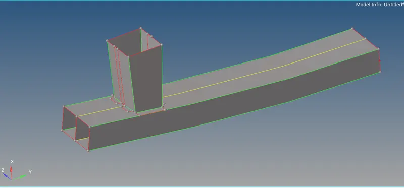
use these commands :
- Surface drag along vector pannel
- Surface edit trim with surface
- Surface edit extend line to surface
- Deleting surface > quick edit panel
- Suppressing edges > quick edit panel
- Split surface to line > quick edit pannel
- Replace point to retain point > quick edit panel
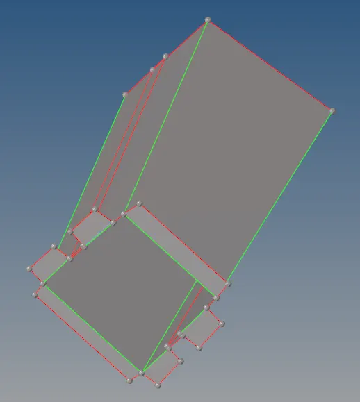
step 3. 2D meshing with element size 6mm
*2D--Automesh--select surface --element size 6mm-- mixed type mesh--mesh.
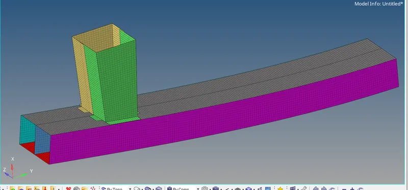
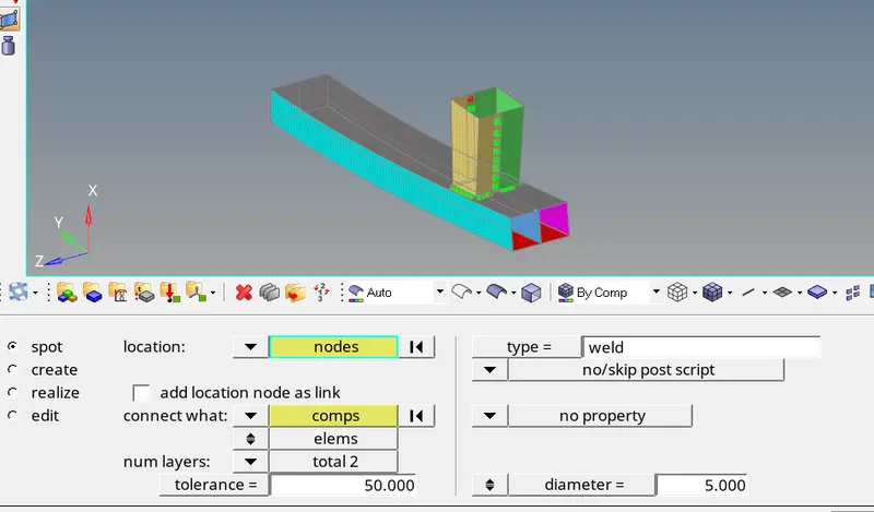
step 4. Connecting whole parts with 2D connectors, spot weld connector is good to use here.
*2D--connectors--spot--type weld--select node list--select 2 components--tolerance 5mm--diameter 5mm--create.
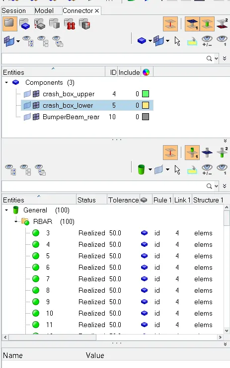
We can see that a new tab has been created with the name of connector and we can see how many connectors have been created and we should make sure that connectors should realized.
objective 1 :
Obj 2:
case 1- Simulating and analysing crash tube model as it is given in the challenge.
step 1: Open Hyperworks in Radioss solver.
step2: Import solver desk crash_tube_0000.rad file
step 3: Simulating model as it is
*Analysis--radioss--save as input case1_crash_tube_0000.rad file--checkbox include collectors--write (-nt 4) in options--click radioss
step 4: switch to Hyperview
step 5: select local model and result case 1_crash_tube.h3d file
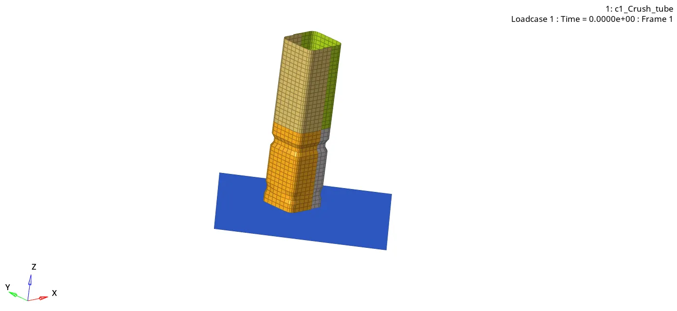
step 6 : checking the number of cycles it takes, energy error, mass error and simulation time.
> Number of cycles = 83469
> Energy error = -3.8 %
> Mass error = 0.0
> Simulation time = 88.03 s
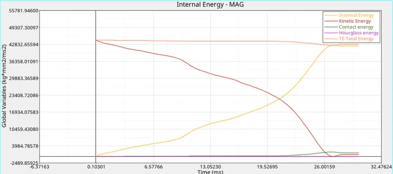
srep 7: Observing internal, kinetic, hourglass, contact and total energy. Switch to hypergraph 2D, Upload case1_crash_tube T01 file
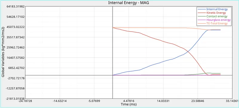
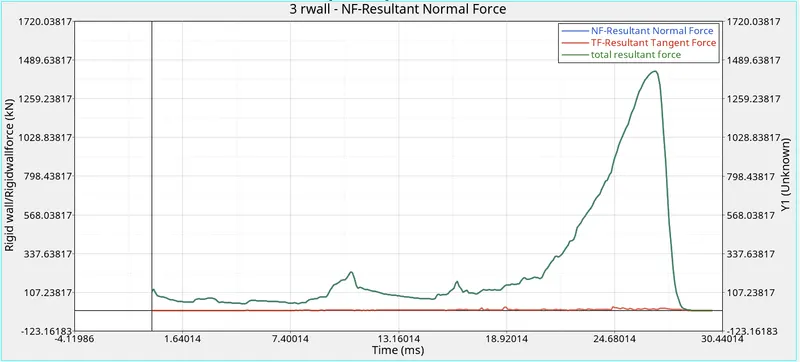
Step 8: Observing Rigid Wall froces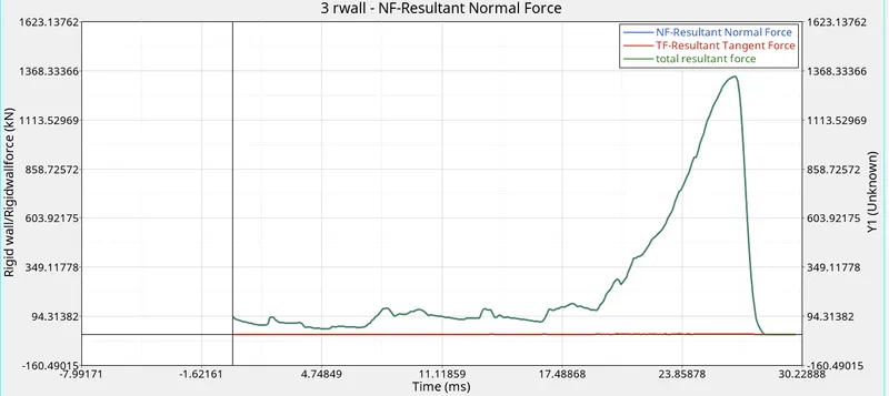
Case 2. Simulating and analysing crash tube model after changing Inacti= 6 in groups self contact collector.
step 1: Open Hyperworks in Radioss solver. Import solver desk crash_tube_0000.rad file
step 2 : Changing inacti = 6 in group's self contact collector.
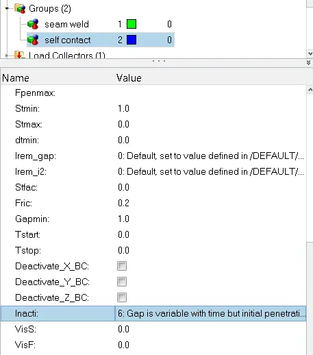
step 3: Simulating model as it is
*Analysis--radioss--save as input case2_crash_tube_0000.rad file--checkbox include collectors--write (-nt 4) in options--click radioss
step 4: switch to Hyperview
step 5: select local model and result case 2_crash_tube.h3d file
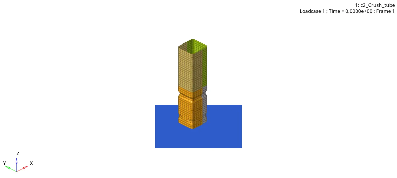
step 6 : checking the number of cycles it takes, energy error, mass error and simulation time.
> Number of cycles = 83469
> Energy error = -3.8 %
> Mass error = 0.0
> Simulation time = 147.14 s
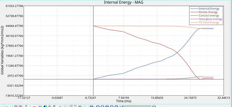
srep 7: Observing internal, kinetic, hourglass, contact and total energy. Switch to hypergraph 2D, Upload case2_crash_tube T01 file
Step 8: Observing Rigid Wall froces
Case 3. Simulating and analysing crash tube model after creating type 11 parameters
step 1: Open Hyperworks in Radioss solver. Import solver desk crash_tube_0000.rad file
step 2: Creating Type 11 parameters
step 3: Simulating model as it is
*Analysis--radioss--save as input case3_crash_tube_0000.rad file--checkbox include collectors--write (-nt 4) in options--click radioss
step 4: switch to Hyperview
step 5: select local model and result case 3_crash_tube.h3d file
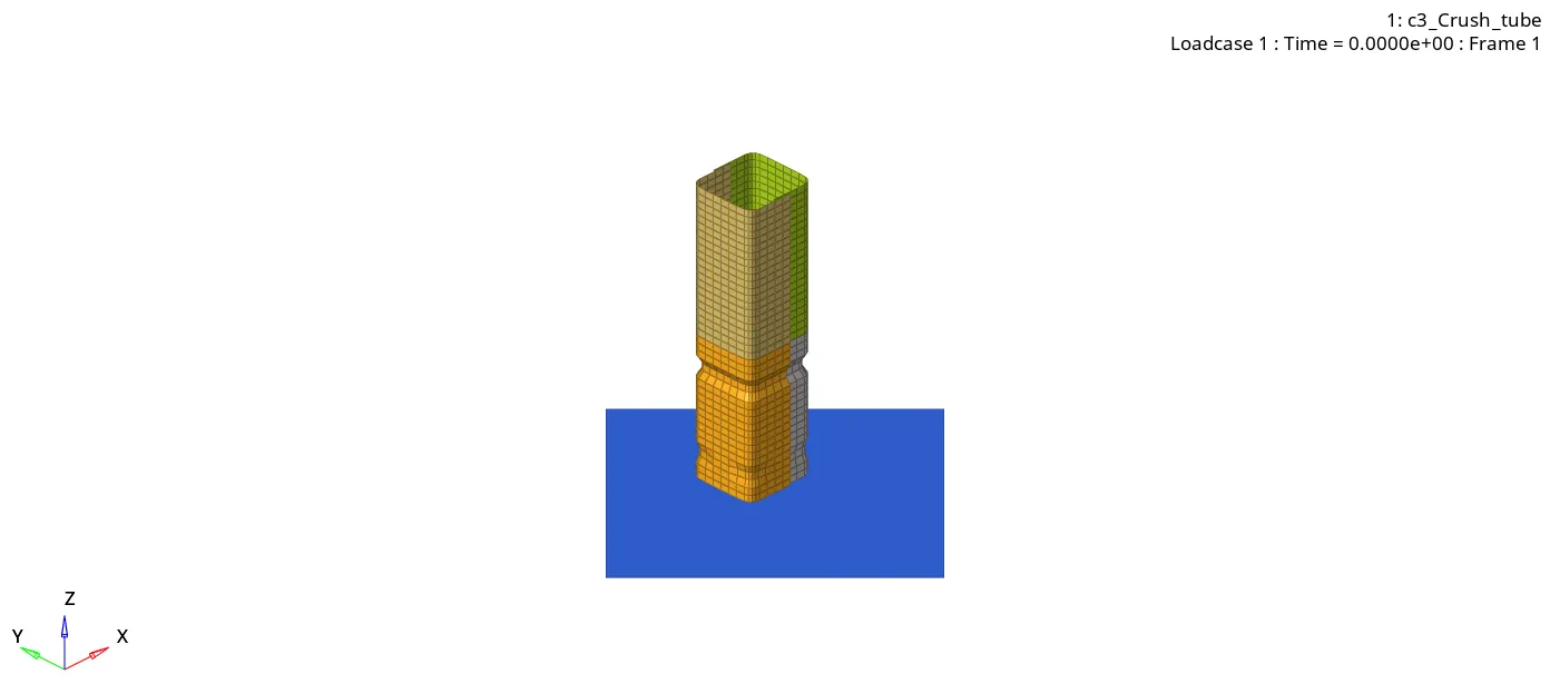
step 6 : checking the number of cycles it takes, energy error, mass error and simulation time.
> Number of cycles = 412905
> Energy error = -3.1%
> Mass error = 0.0
> Simulation time = 620.94
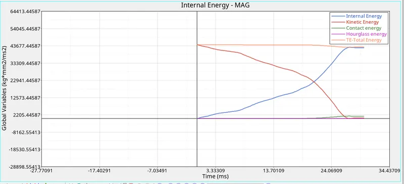
srep 7: Observing internal, kinetic, hourglass, contact and total energy. Switch to hypergraph 2D, Upload case3_crash_tube T01 file
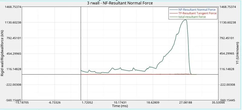
Step 8: Observing Rigid Wall froces
Case 4. Simulating and analysing crash tube model after removing both notches and boundary conditions
step 1: Open Hyperworks in Radioss solver. Import solver desk crash_tube_0000.rad file
step 2: Removing all notches and deleting Boundary conditions
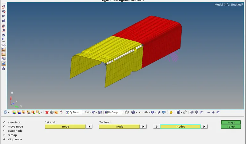
> Removing notches by using align nodes pannel
*Shift+F8 leads to nodes edit
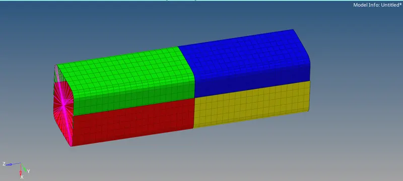
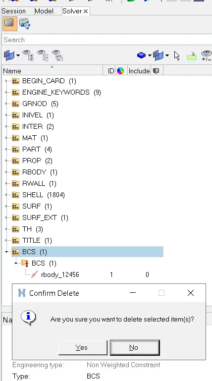
> Deleting boundary condition
step 3: Simulating model as it is
*Analysis--radioss--save as input case4_crash_tube_0000.rad file--checkbox include collectors--write (-nt 4) in options--click radioss
step 4: switch to Hyperview
step 5: select local model and result case 4_crash_tube.h3d file
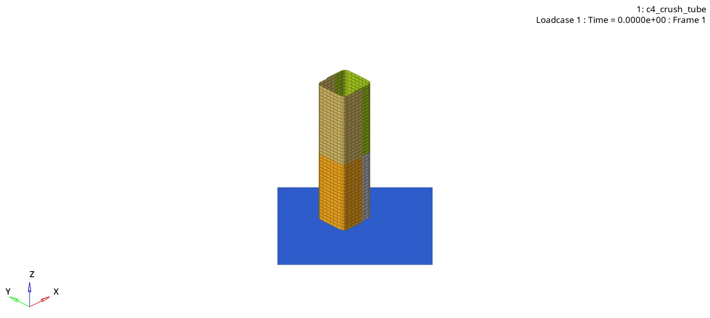
step 6 : checking the number of cycles it takes, energy error, mass error and simulation time.
> Number of cycles = 78367
> Energy error = -3.0%
> Mass error = 0.0
> Simulation time = 58.33 s
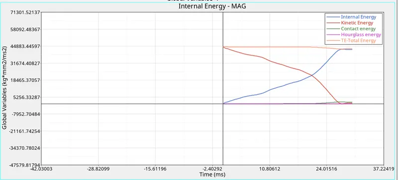
srep 7: Observing internal, kinetic, hourglass, contact and total energy. Switch to hypergraph 2D, Upload case4_crash_tube T01 file
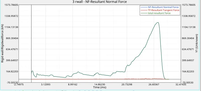
Step 8: Observing Rigid Wall froces
Case 5. Simulating and analysing crash tube model after creating a new notch in the middle of the whole component
step 1: Open Hyperworks in Radioss solver. Import solver desk case 4_crash_tube_0000.rad file
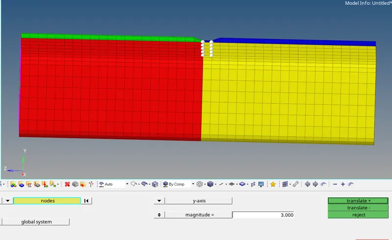
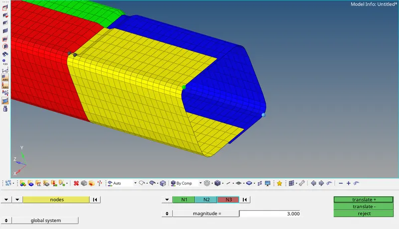
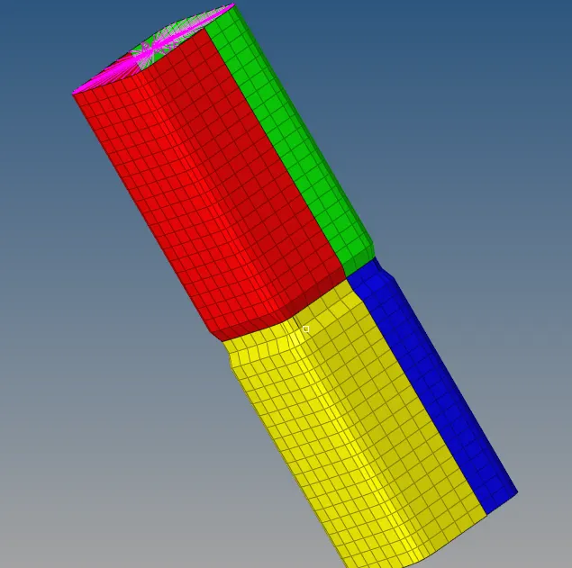
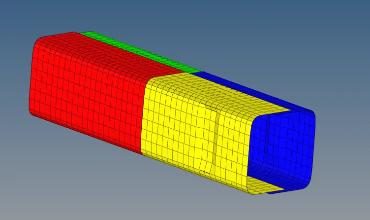
step 2: Creating a new notch in the middle of the whole component.
- Translating nodes, by giving vector direction at flat surfaces. At bent we have to give N1, N2 for proper notch.
step 3: Simulating model as it is
*Analysis--radioss--save as input case5_crash_tube_0000.rad file--checkbox include collectors--write (-nt 4) in options--click radioss
step 4: switch to Hyperview
step 5: select local model and result case 5_crash_tube.h3d file
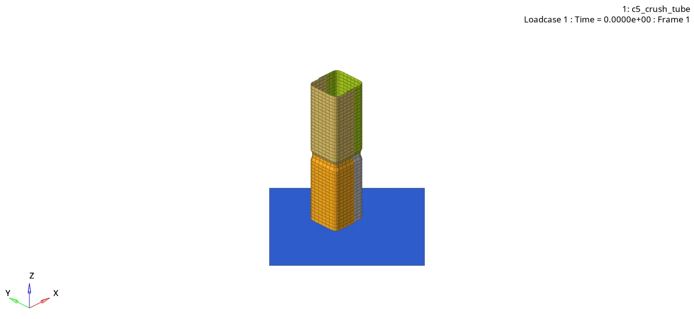
step 6 : checking the number of cycles it takes, energy error, mass error and simulation time.
> Number of cycles = 115737
> Energy error = -2.9%
> Mass error = 0.0
> Simulation time = 201.92 s
srep 7: Observing internal, kinetic, hourglass, contact and total energy. Switch to hypergraph 2D, Upload case5_crash_tube T01 file
Step 8: Observing Rigid Wall froces
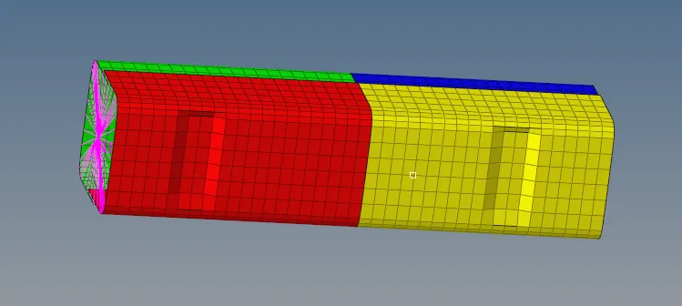
Case 6. Simulating and analysing crash tube model after creating a new notch on opposite two faces of the component
step 1: Open Hyperworks in Radioss solver.Import solver desk crash4_tube_0000.rad file
step 3: Simulating model as it is
*Analysis--radioss--save as input case6_crash_tube_0000.rad file--checkbox include collectors--write (-nt 4) in options--click radioss
step 4: switch to Hyperview
step 5: select local model and result case 6_crash_tube.h3d file
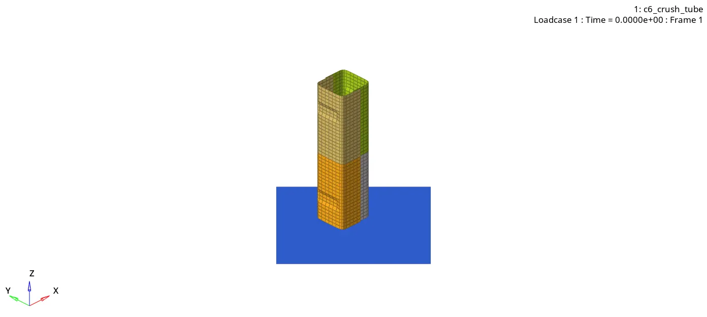
step 6 : checking the number of cycles it takes, energy error, mass error and simulation time.
> Number of cycles = 93257
> Energy error = -4.0%
> Mass error = 0.0
> Simulation time = 170.56 s
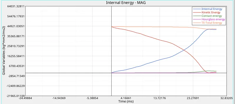
srep 7: Observing internal, kinetic, hourglass, contact and total energy. Switch to hypergraph 2D, Upload case6_crash_tube T01 file
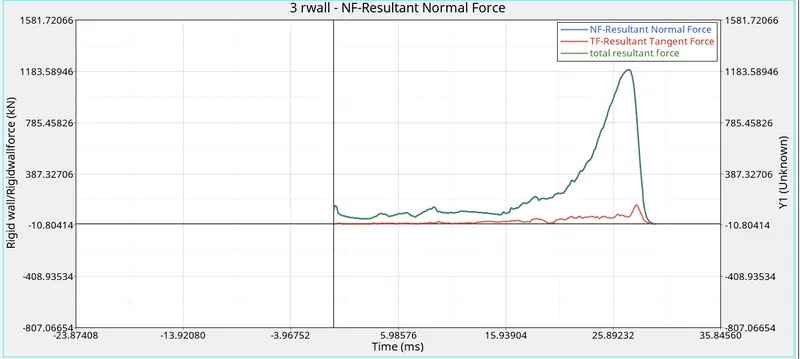
Step 8: Observing Rigid Wall froces
OBSERVATION :
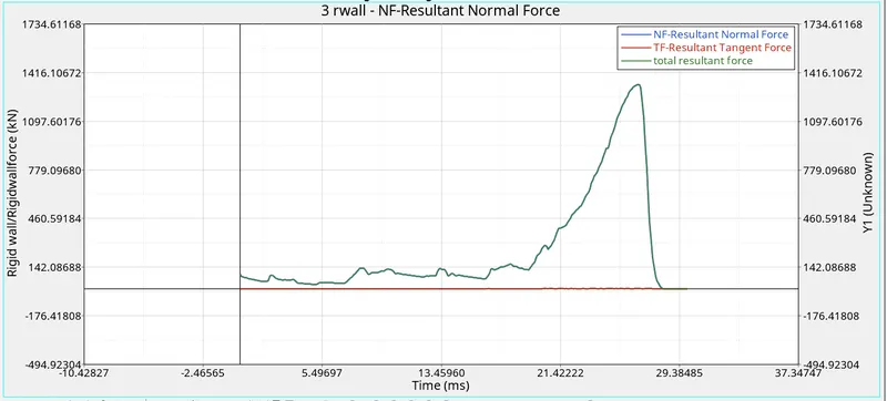
Case 1: Here notches are away from the middle of the component and four more notches are made on the same side os each corner. Total reultant forces reach a peak of 1350KN at 26.5 seconds and kinetic energy and internal energy intersect each other at 22500KN at 21 seconds.
Case 2: Here we won't find any difference after changing it to inacti=6, we didn't make changes to the structure of the crash tube, the results we got are almost same as 1st case.
Case 3: Here we create Type11 contact, we didn't make changes to the structure of the crash tube, we saw that total resultant force was decreased to 1200KN at27 seconds. Here also kinetic energy and internal energy intersect each other at 22500KN at 21 seconds.
Case 4: Here we removed both notches from the crash tube, so there are No Notches in the component, it was completely aglin, we saw that there is sudden increase of total resultant force after 0 seconds and then it reaches peak at 1000KN at 28 seconds. we also saw that their was disturbance in resultant tangent force in the rigid wall graph between 15 to 30 seconds. Here also kinetic energy and internal energy intersect each other at 22500KN at 21 seconds.
Case 5: Here we make notches in the middle around the component, we saw again increase in the total resultant forces earlier case with 1210KN at 27.5 seconds
Case 6: Here we make notches in the opposite face of the component, we saw thet their is sudden increase in total resultant force at 10 seconds due to opposite notches, which we didn't found in earlier cases, but peak of total resultant force again decreased to 1020KN at 27.5 seconds. Here Kinetic and internal energy intersect each other at just 20 seconds with 22500KN force, which also we didn't saw in earlier cases.
Cases NO. of cycles Mass error energy error simulation time (seconds)
1 83469 -3.8% 0.0 88.03
2 83469 -3.8% 0.0 147.14
3 412905 -3.1% 0.0 620.94
4 78367 -3.0% 0.0 58.33
5 115737 -2.9% 0.0 201.92
6 93257 -4.0% 0.0 170.56
Learnings :
- 2D Meshing
- Joining components with 2D spot weld connectors.
- Importing starter file runname_0000.rad file
- Using Radioss command
- Running runname.h3D file in Hyperview to see animation
- Reading runname_0001.out file
- Using Hypergraph 2D
- Observing Energies graph and rigid wall froces
- Creating notches
- Changing Type 11 parameters.