Assignment 5-RADIOSS Interfaces & Study of Effect of Notches Challenge
OBJECTIVE :
To mesh the given bumper model with 2d quad elements of size 6mm and provide proper connections to them. To create various interface cases for the given crash tube, study the behavior of crash tube by modifying notches and compare the outcomes.
Here are the given scenarios to be performed:
- Run the crash tube model as it is.
- Change the Inacti=6 and run.
- Create the type 11 contact and run.
- Remove both notches and remove boundary condition on rigid body node then run.
- Create a new notch in the middle ,select the whole section and run.
- Create a new notch with nodes only from opposing 2 faces and run.
PROCEDURE :
1. Import the given bumper geometry in the Hypermesh window and check for the geometrical errors in it. Here is the given parent geometry :
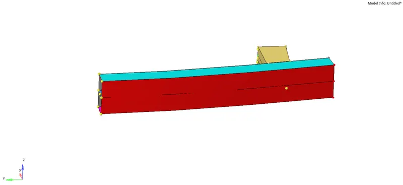
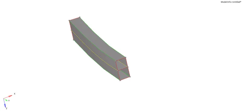
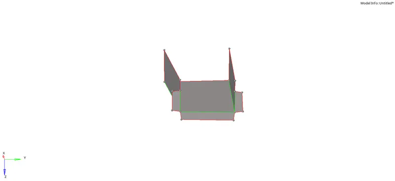
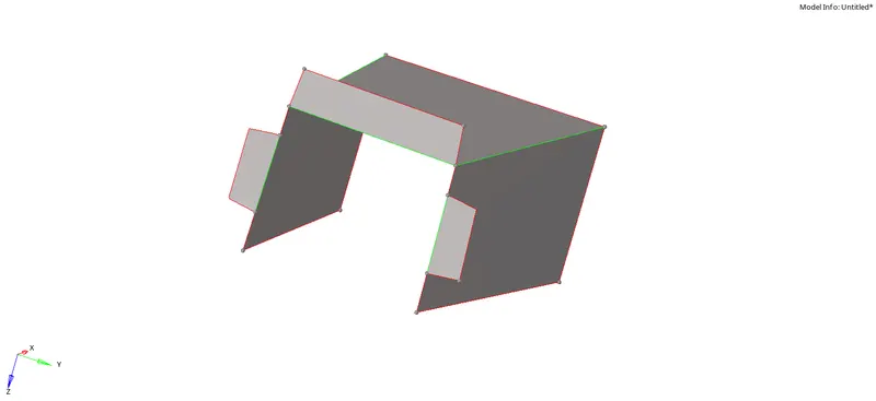
2. There are certain irregularities in the geometry to be corrected. We can extend the surface respectively and then use replace points and project points option in the tools tab to correct all the geometrical errors in the given geometry. Here is the corrected geometry :
3. Now, go to 2D >> Automesh >> Select the surfaces to be meshed >> Mesh size as 6mm (given) >> Mesh type : Mixed and hit mesh to create mesh on the surface. Keeping equal number of nodes in the opposite sides would eliminate tria element formation. Here is the meshed model :
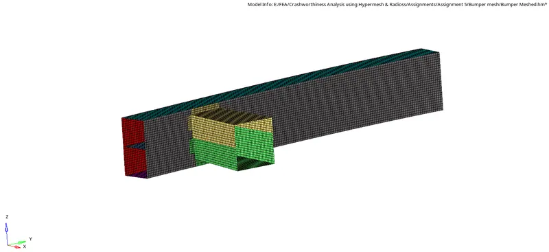
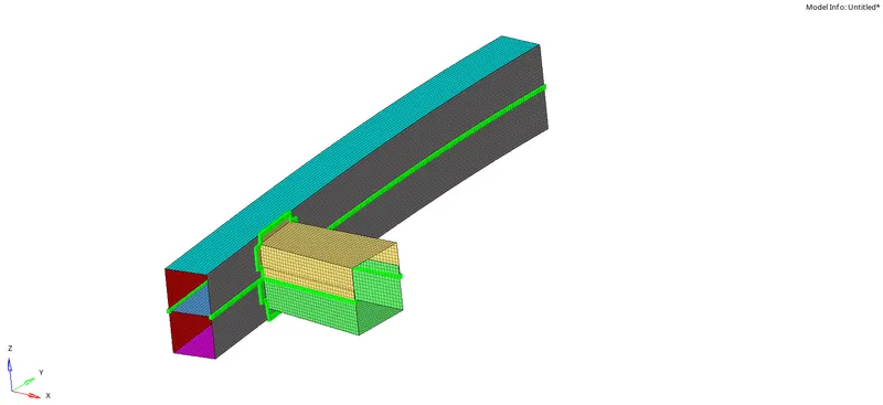
4. Once the meshing is done, go to 2D>> Connectors >> Spot/Seam weld >> Select the node path >> Select the components to be connected >> Provide tolerance value >> Select the element type (Plot/weld/hexa adhisive/spring/bar/rigid etc) >> and click create to provide proper connections to the crash box and the bumper. Here is the final model :
Crash Tube Interface cases :
Case 1 : To run the given model as it is (Type 3 & 7)
1. Firstly, Import the given radioss input file in the Hypermesh (0000.rad file) and then go to the Analysis option.
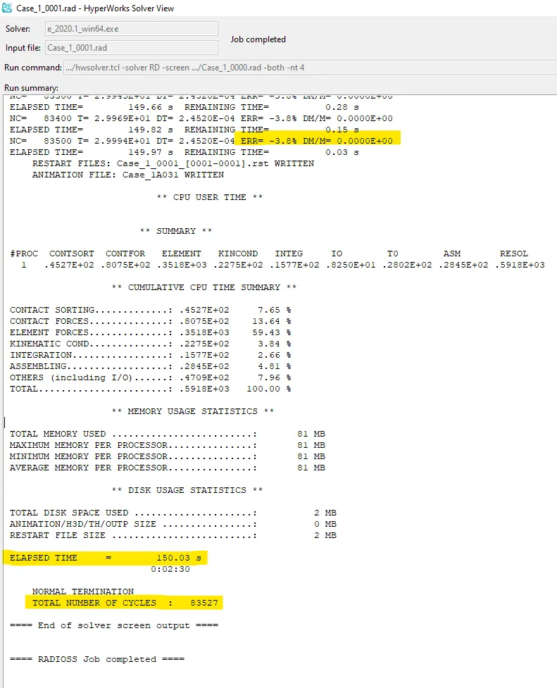
2. Now, Set the file location and pathway and click on include connectors and provide options as -nt 4 ( no.of.threads ) and then click on run to perform the analysis.
3. We can see that the energy error in this case was about -3.8% and the mass error remained 0 which is well within the desirable range.
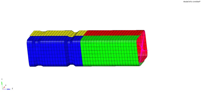
4. Open the result file (.h3d ) in the Hyperview and T01 file in the Hypergraph to check the results and the animation file.
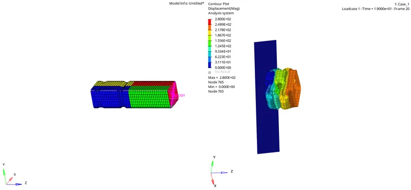
Displacement :
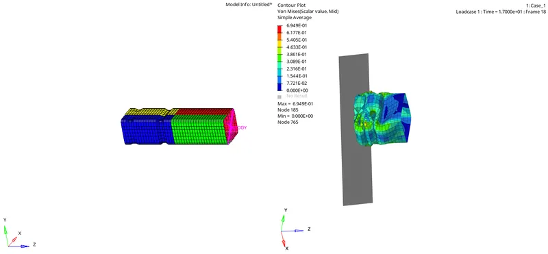
Vonmises stress :
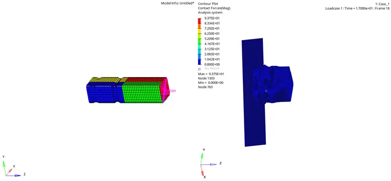
Contact force :
The maximum displacement was about 280mm
The maximum stress produced was about 0.694 Kg/mm2
The contact forces produced in this case is about 93.75 KN
GLOBAL VARIABLES :
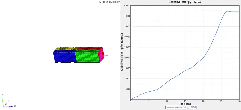
Internal energy :
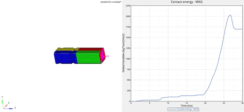
Contact energy :
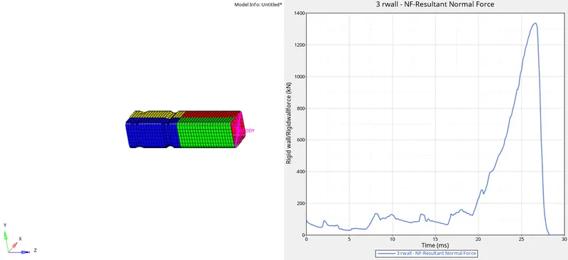
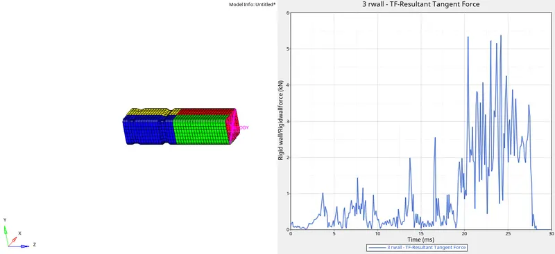
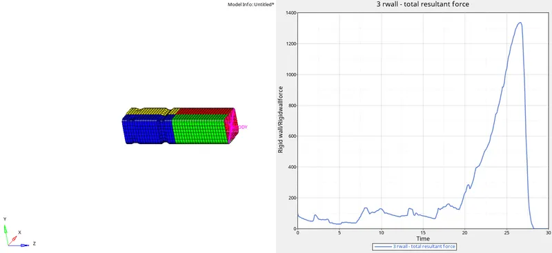
Rigid wall forces :
The Internal energy increases linearly as the deformation progresses. The contact energy of this case is found zero for a certain extent and once the deformation starts, the elements would deform and it would cause internal friction among the elements as the deformation progresses which gives rise to the contact energy.
The Rwall forces resultant is minimum at the beginning and reaches the maximum value at the point where the deformation reaches its maximum ( since elements were deformed and it can't offer more resistance ) and it reaches zero once the deformation has reached zero.
Case 2 : Type 3 & 7 with Inacti = 6
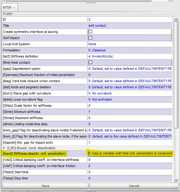
In this case, we should edit the contact interface parameter with the given input ( Inacti = 6 )
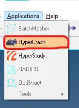
For this reason, we shall open the Hypercrash window. Go to Applications in the Hypermesh and open the Hypercrash.
It would ask for the default unit settings, set the units as kN,mm,ms,kg and run the software.
Now, open the file through Import >> Radioss >> Copy the path extension and paste in the browse area and press Tab >> It would recognize the availble .rad files in the location ( Hypercrash don't has its own file extension ).
Open the given crash tube 0000.rad file in it.
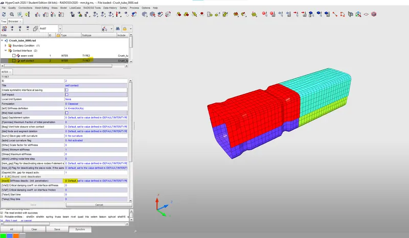
Once it was open, go to Load case >> Contact Interface >> We can see the interface types used in the model, In this case, we have Type 3&7 in it and we should edit the Inacti as 6 ( Gap is variable with time )
Once it was done, Export the model and then open the same in the Hypermesh and run them to see the results :
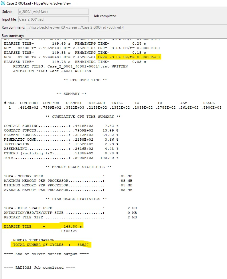
Here we can see that the Energy error and the mass error were well within the acceptable range and so we can proceed and check the results and animation to see the changes.
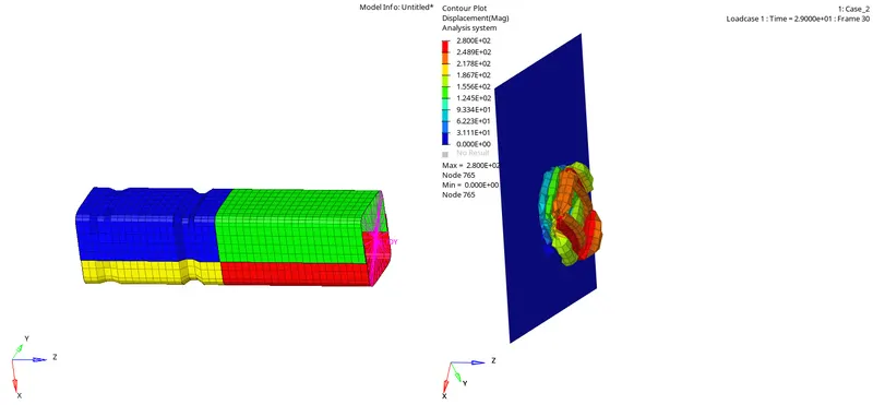
Displacement :
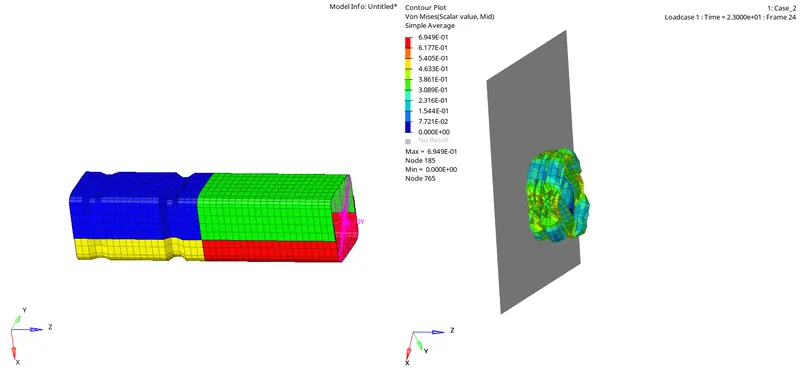
Vonmises stress :
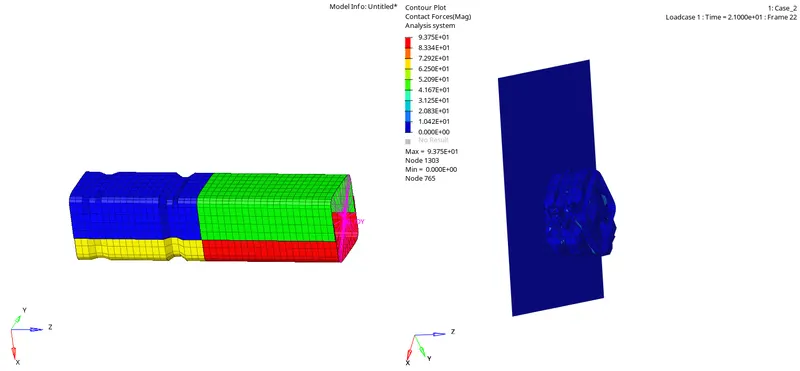
Contact forces :
The maximum displacement was about 280 mm
The maximum stress produced was about 0.6949 Kg/mm2
The contact forces produced was about 93.75 kN
Global Variables :
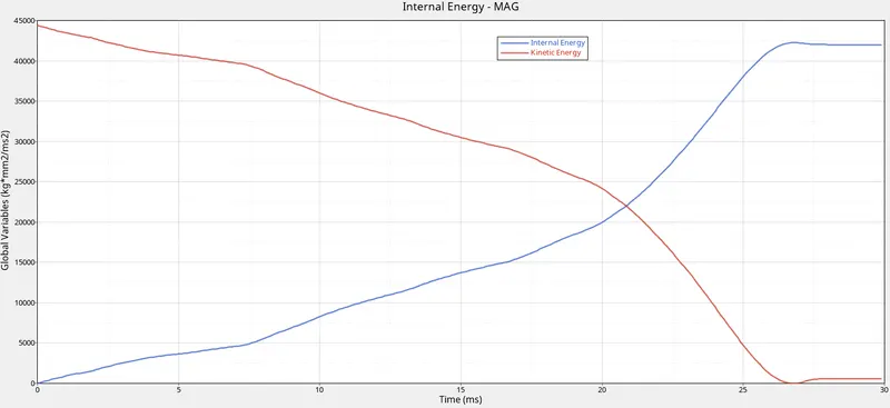
Internal & Kinetic energy :
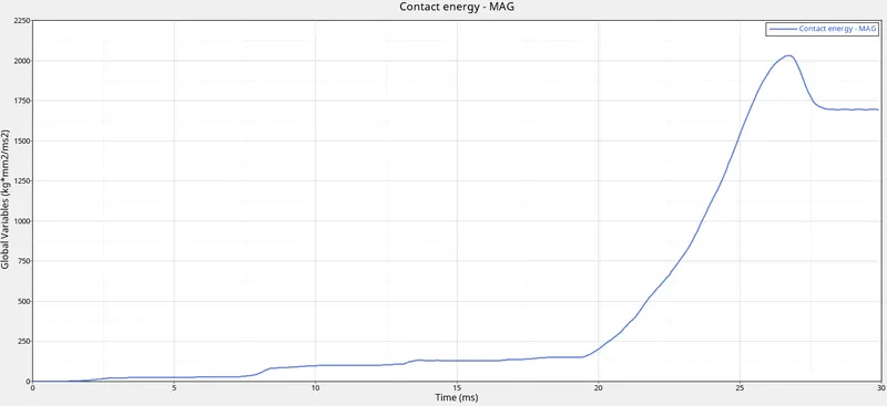
Contact energy :
Rigidwall forces :
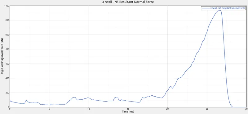
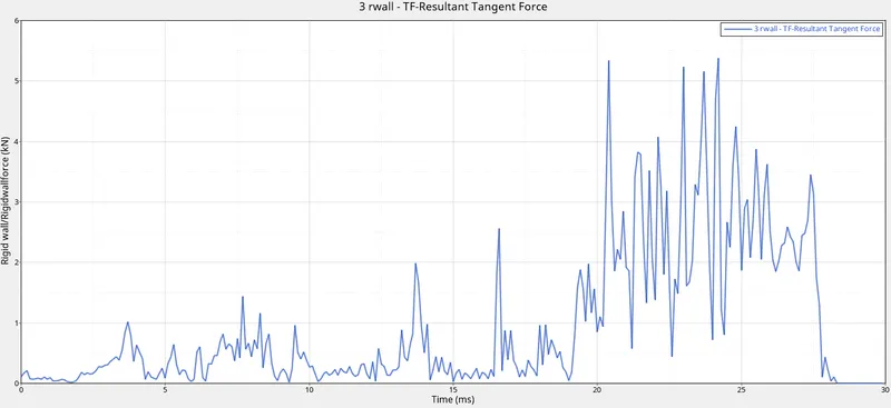
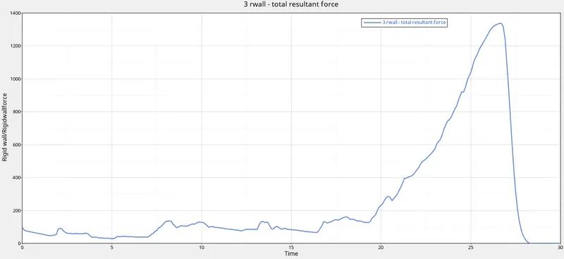
Here, we can see that the Internal energy increases linearly as the deformation starts. Similarly the Contact energy also increases and it reaches the maximum value when the crash tube has been deformed to its maximum extent and then decreases and maintains a constant value.
The rigid wall forces doesn't seem different when compared to the previous case. It almost looks similar to the previous case.
Case : 3 ( Type 3, 7 & 11 )
In this case, we are adding one more contact interface ( Type 11 or the edge to edge interface ).
So with the similar setup, Export the input .rad file to the Hypercrash window. Once the file is open, go to Load case >> Contact Interface >> Right click >> Create New >> Contact interface >> Type 11.
Now, once it is clicked, it would ask for all the parameters, The slave and the master components were to be selected. Here both the slave and the master components were the same and there were several other parameters like minimum stiffness, minimum gap etc
Here are the other parameters which are to be entered :
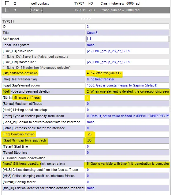
With all these parameters set, now export the file to the Hypermesh window and run this to see the changes in the behaviour of the crash tube.
The energy error was found to be -3.8% and the mass error was 0 which was well within the acceptable range.
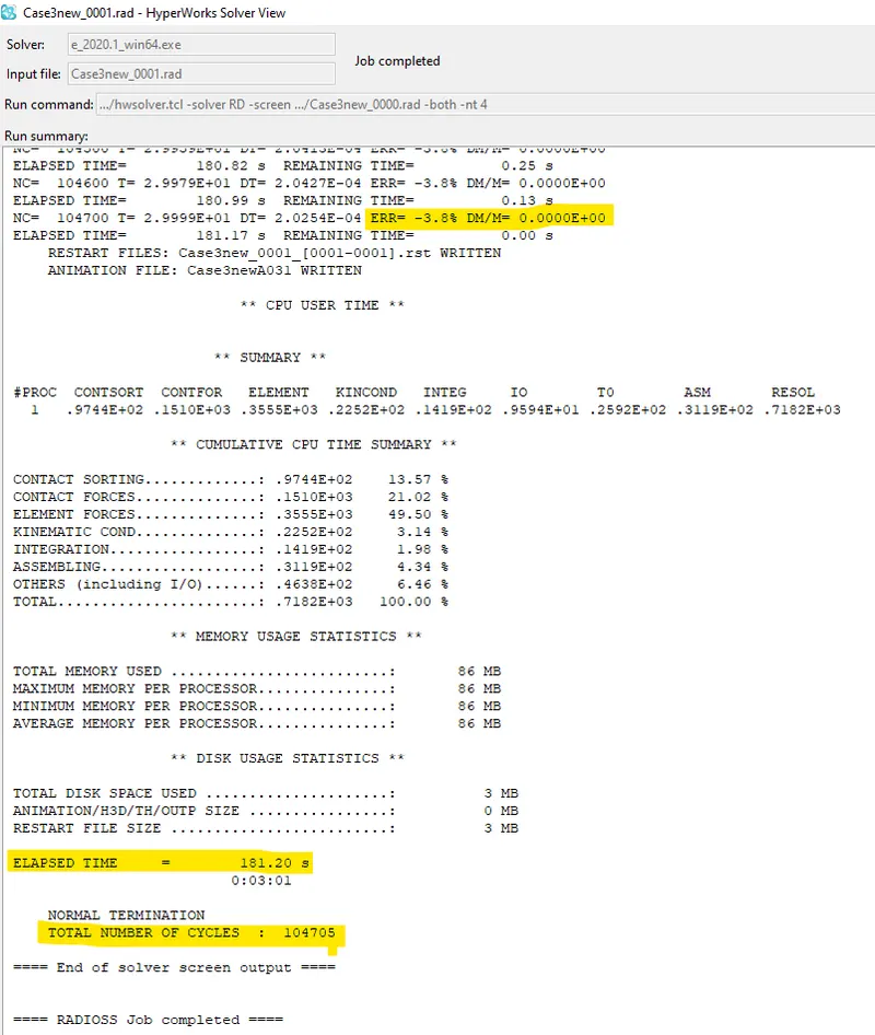
Displacement :
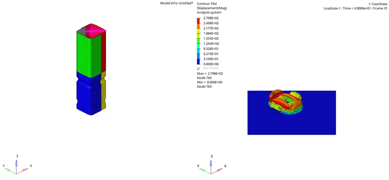
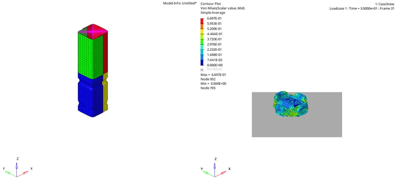
Vonmises stress :
Contact forces :
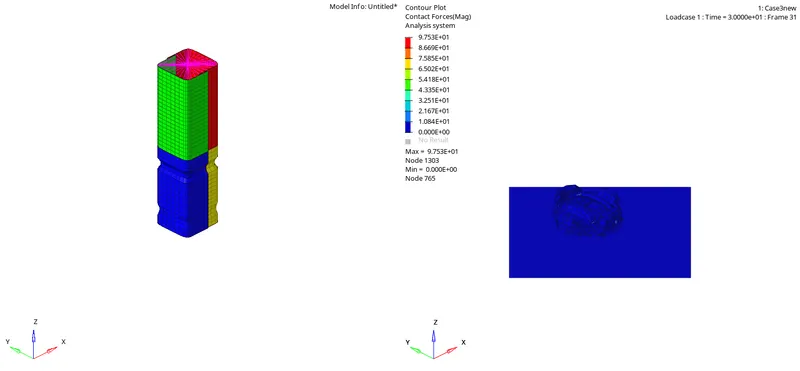
The maximum displacement was about 279.8mm
The maximum stress produced was about 0.6697 Kg/mm2
The contact forces produced was about 97.53 kN
Global variables :
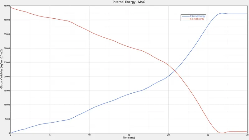
Internal and kinetic energy :
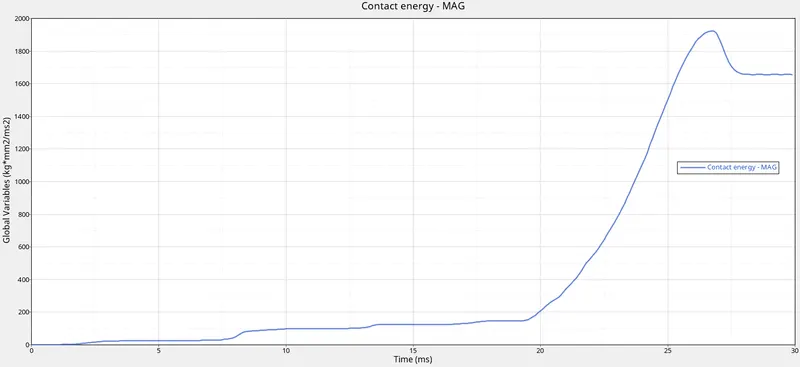
Contact energy :
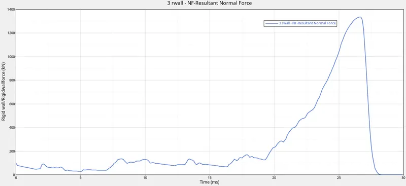
Rigidwall forces :
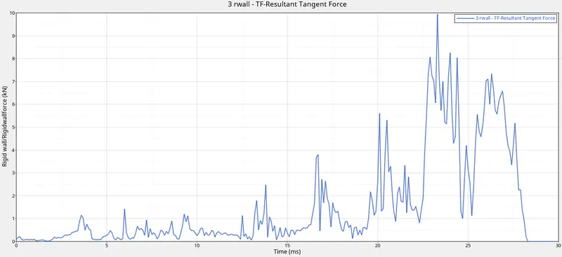
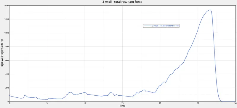
The internal energy increases linearly as the deformation progresses and it goes in a constant value once the deformation is completed. Similar to the previous case the contact forces also increases linearly and reaches the maximum value at the highest deformation stage and it falls down once the maximum deformation has crossed and maintains a constant value.
The rigid wall forces were similar to the other case however the tangent resultant force seems siginificantly higher than the other cases with the usage of Type 11 interface.
Case 4 : With no notch and no boundary condition :
In this case, we need to remove all the notches in the crash tube and also we need to remove the boundary conditions which were applied to the rigid body.
Similar to other case, Open up the Hypercrash window and import the starter input file of the crash tube and go to Load case >> Boundary condition.
Here we can see that the DOF's were constrained to the rigid body, unconstrain all the DOF's applied and then export the file to the Hypermesh window.
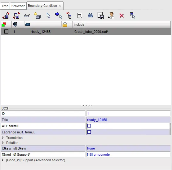
Now, Open the file in the Hypermesh window, to remove all the notches present, we can use align node function. Here is the model in which all the notches were removed :
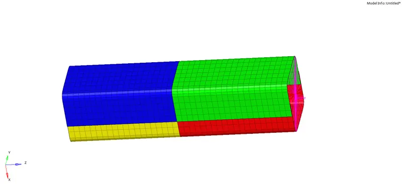
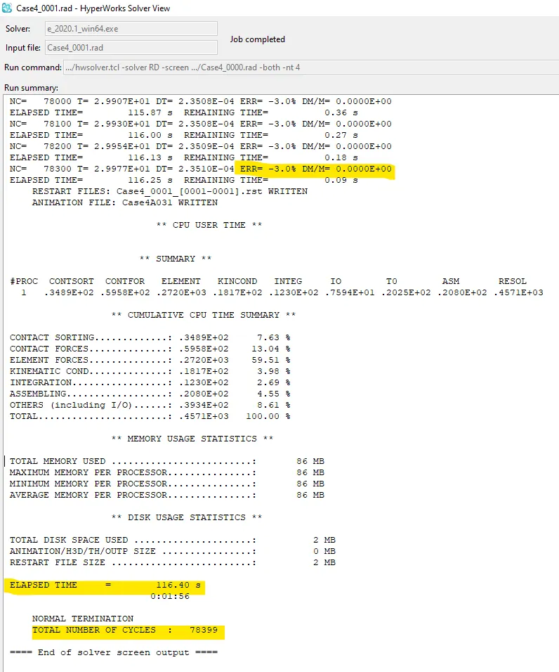
Now, run the input file, The energy error is about -3.0 % and the mass error is 0 which is within the acceptable range. Open the .h3d file in the Hyperview and the T01 file in the Hypergraph to see the animation and the global variables.
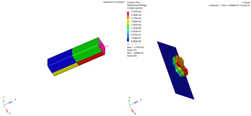
Displacement :
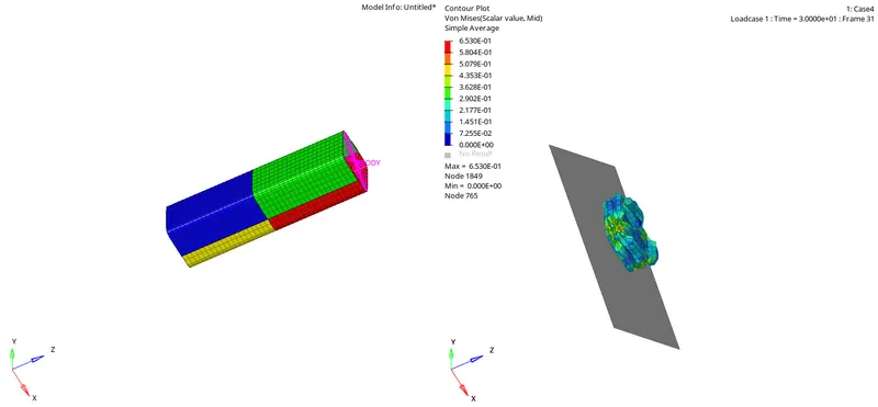
Vonmises stress :
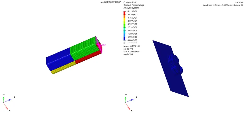
Contact forces :
The maximum displacement was about 279.7mm
The maximum stress produces was about 0.6530 Kg/mm2
The contact force produced was about 61.15 kN
We can see that the contact forces were less in this case since there are no notches there won't be much of contact energy and the force.
Global variables :
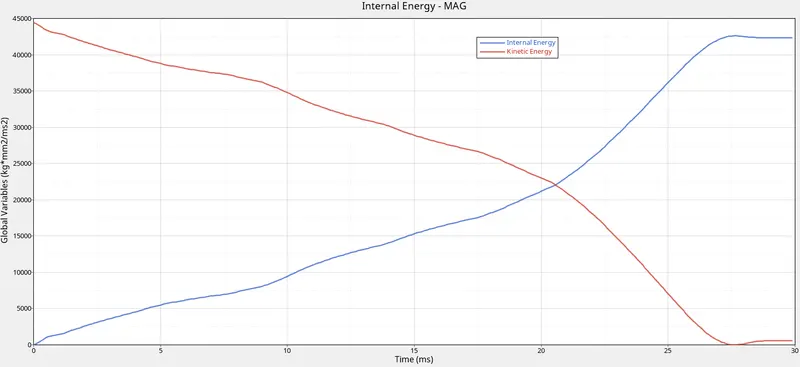
Internal and kinetic energy :
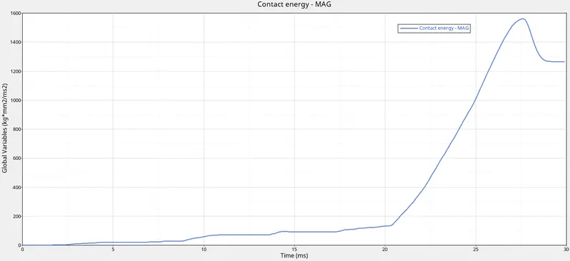
Contact energy :
Rigidwall forces :
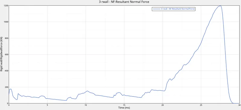
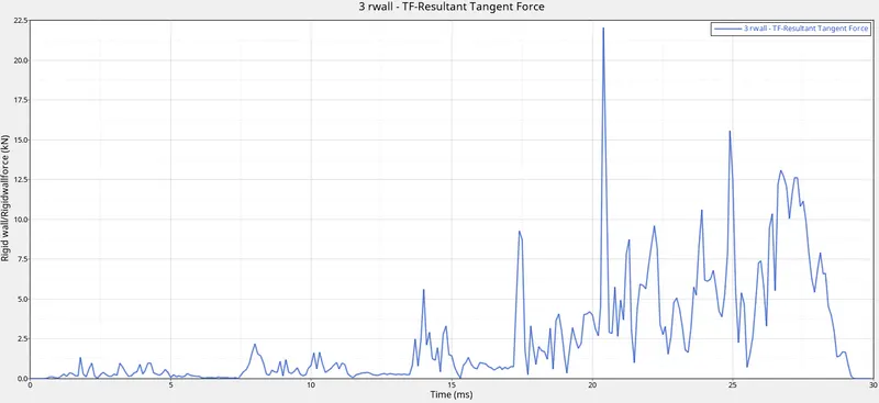
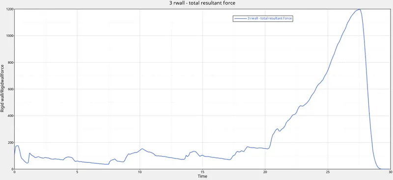
The internal energy varies linearly as the material deforms. The major difference is seen in the contact energy. Since the notches were deleted in this case there won't be much of contact energy produced.
The resultant normal force is comparitively lesser than the previous case as there are no notches and so there won't be much of stress.
Case 5 : Creation of new notch in middle :
In this case, Using the previous file in which all the notches were removed, create notch in the middle of the crash tube alone and keep all the parameters unchanged and run the analysis.
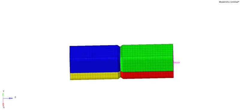
With this setup, on running we observe the energy error as -2.9 % and the mass error as 0. Here are the results and the animation :
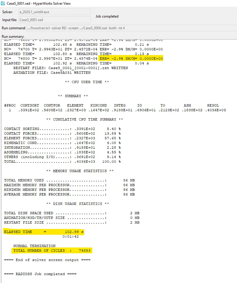
Displacement :
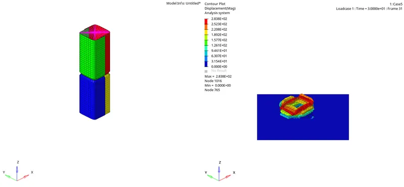
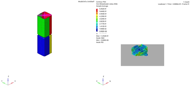
Vonmises stress :
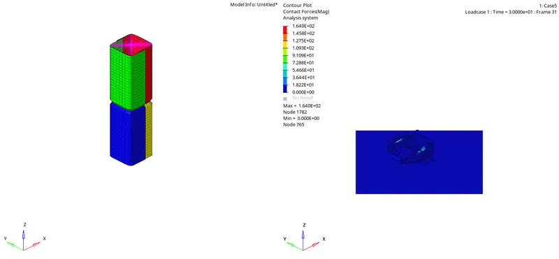
Contact force :
The maximum displacement was about 283.8mm
The maximum stress produced was about 0.6352 Kg/mm2
The contact force produced was higher at 164 kN
This is due to the fact that the presence of the notch with all the boundary condition removed. The notch in the center which is an irregularity, increases the stress formation there and thus the deformation and the stress produced were initially there.
Global variables :
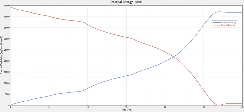
Internal and kinetic energy :
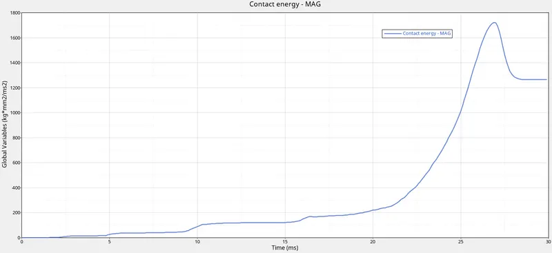
Contact energy :
Rigidwall forces :
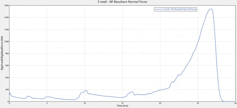
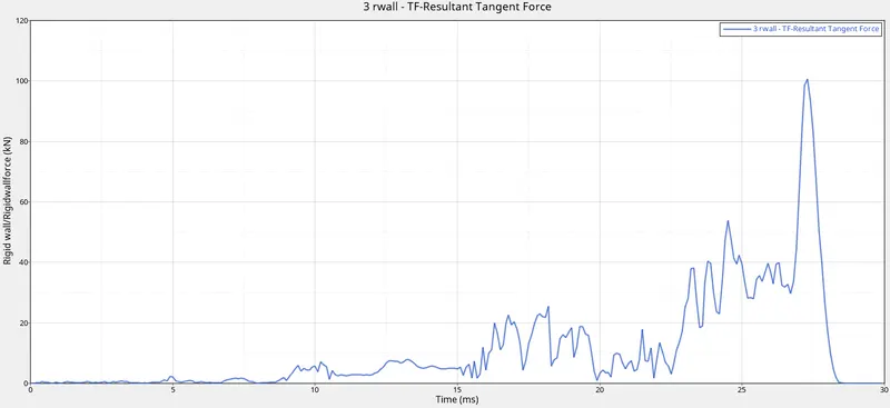
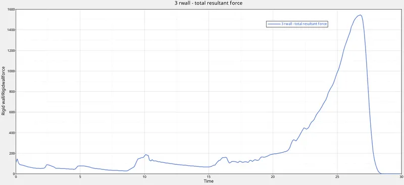
The Internal energy increases linearly as the other cases. The contact energy has increased than the previous case seemingly. This is due to the fact that there is a notch in the center.
The resultant normal force is also higher than the previous case since the notch has paved way for deformation and stress increase.
Case 6 : Notch with nodes only opposing from 2 face :
In this case, Use the previous crash tube file and align the nodes along two sides in the center and keep only two side of the notch and rest all the parameters were similar. Now, run the solver to get the results.
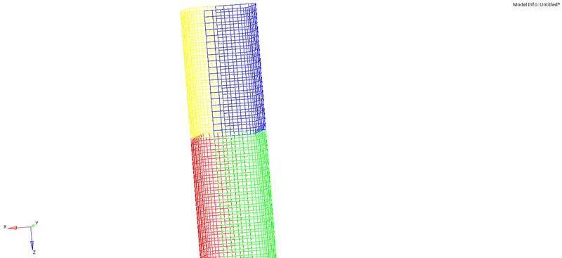
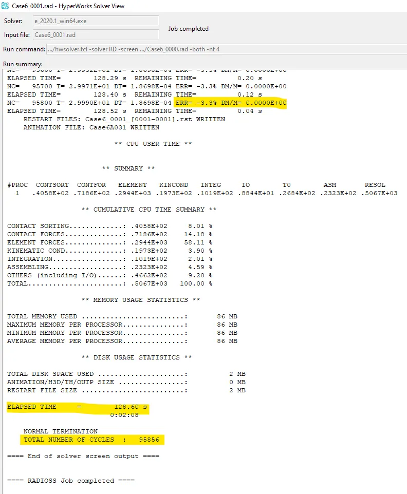
The energy error was about -3.3% and the mass error is 0 which is within the acceptable range.
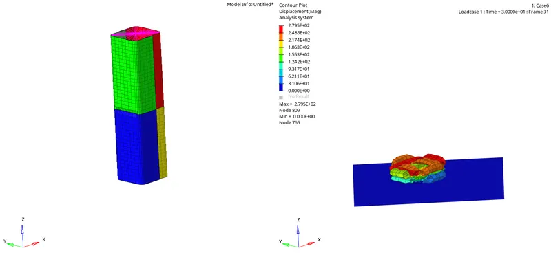
Displacement :
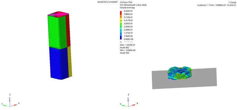
Vonmises stress :
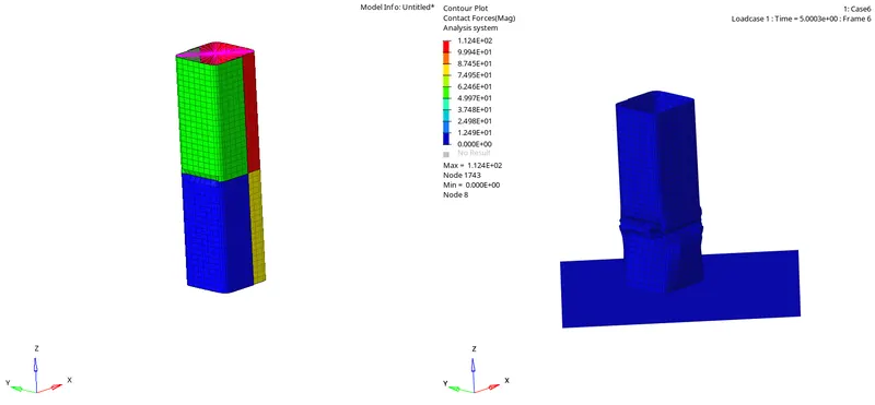
Contact force :
The maximum displacement produced was about 279.5mm
The maximum stress produced was 0.6625 kg/mm2
The maximum contact force produced was 112.4 kN
This is clearly lesser than the previous case which indicates notches would greatly affect the deformation and the contact force. Since the notches were present only on two side rather than all for sides as of in previous case, the contact force is lesser.
Global variables :
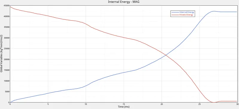
Internal and kinetic energy :
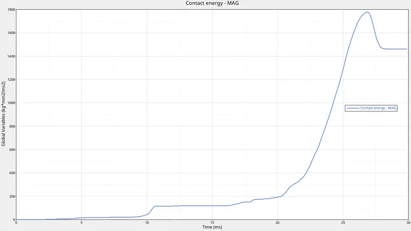
Contact energy :
Rigidwall forces :
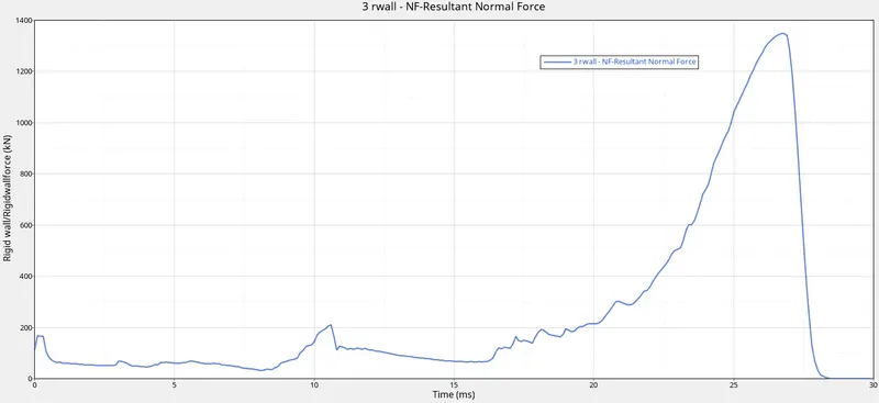
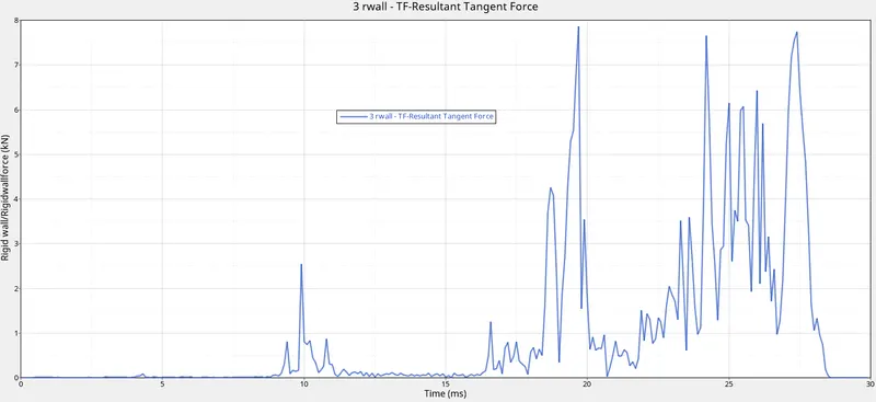
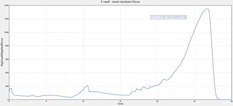
The Internal energy increases linearly as all the case. The contact energy is slightly lesser than the previous case since the notches were present only on two sides rather than all sides as of in the previous case.
The resultant force is also lesser than the previous case since the notches were present only on the two sides.
All the scenarios has been run and the results were recorded.
Contact Interface & Notches :
| Case | Displacement(mm) | Vonmisses stress (kg/mm2) | Contact Force (kN) | Internal Energy (kg.mm2/ms2) |
Contact Energy (kg.mm2/ms2) |
Total Resultant Force |
| 1 (Type 3&7) | 280 | 0.694 | 93.75 | 43000 | 2025 | 1300 |
| 2 (Type 3&7 with Inacti =6) | 280 | 0.6949 | 93.75 | 43000 | 2025 | 1300 |
| 3 (Type 3,7&11) | 279.8 | 0.6697 | 97.53 | 43000 | 1900 | 1300 |
| 4 (No notches) | 279.7 | 0.6530 | 61.15 | 43000 | 1550 | 1200 |
| 5 (Center notch) | 283.8 | 0.6352 | 164 | 43000 | 1700 | 1550 |
| 6 (Notch along 2 sides) | 279.5 | 0.6625 | 112.4 | 43000 | 1680 | 1300 |
RESULT :
We can see that the Case 3 with Type 3,7,11 interface provided better and accurate result with stress value lesser with almost equal displacement. Also the contacct energy seems to be lesser than the other cases.
Wherease in the notches, the center notch has been the highest with all values higher than all the other cases. The tube without any notches has been comparitively lesser in numbers while the notches along two sides is slightly lesser than the one with center notch.This clearly shows the presence of irregularities like Notches and its location would have effects on the results.
Also the Type 7,11 in combination has given the accurate results.