Assignment 5-RADIOSS Interfaces & Study of Effect of Notches Challenge
Aim:- To create mesh for bumper assembly, mesh size should be 6mm and simulate the given model with seven different cases in radioss and compare it using various plote.
- Create the mesh for bumper assembly,mesh size should be 6mm.
- Run the crash tube model as it is.
- Change the Inacti=6 and run.
- Create the type 11 contact and run.
- Remove both notches and remove boundary condition on rigid body node then run.
- Create a new notch in the middle ,select the whole section and run.
- Create a new notch with nodes only from opposing 2 faces and run.
Note:
- Plot RWALL forces ,contact forces,internal energy and Create TH/PART for all parts and compare results for all cases.
- Comment your thought on why there is a change in the internal energies.
- How does the notch affect the results?
- Plot energies and note any difference.
Model 1 :- mesh for bumper, mesh size should be 6mm.
- import the model in hypermesh
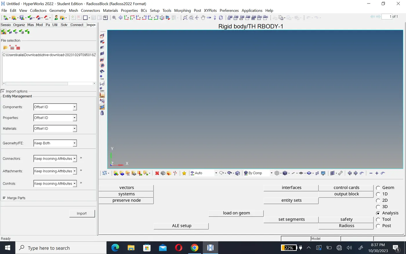
- to open go to the file menu in the stander meanu bar> click open>model>select model and open it.
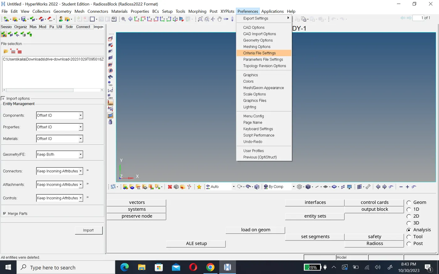
- now assigne the quality criteria click on the preference in the stander bar> criteria setting> give element size 6mm and apply
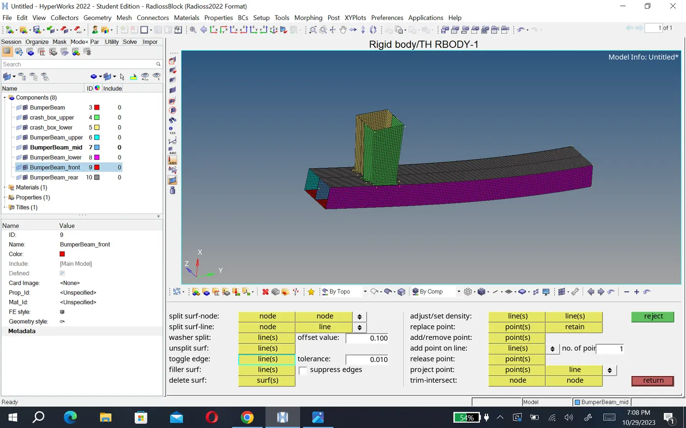
- then go to mesh go 2D panel automesh option>select surface and mesh it.
- After creantig mesh go to connnection between the crash box and rear bumper. so go to connection seam and provide necessary values.
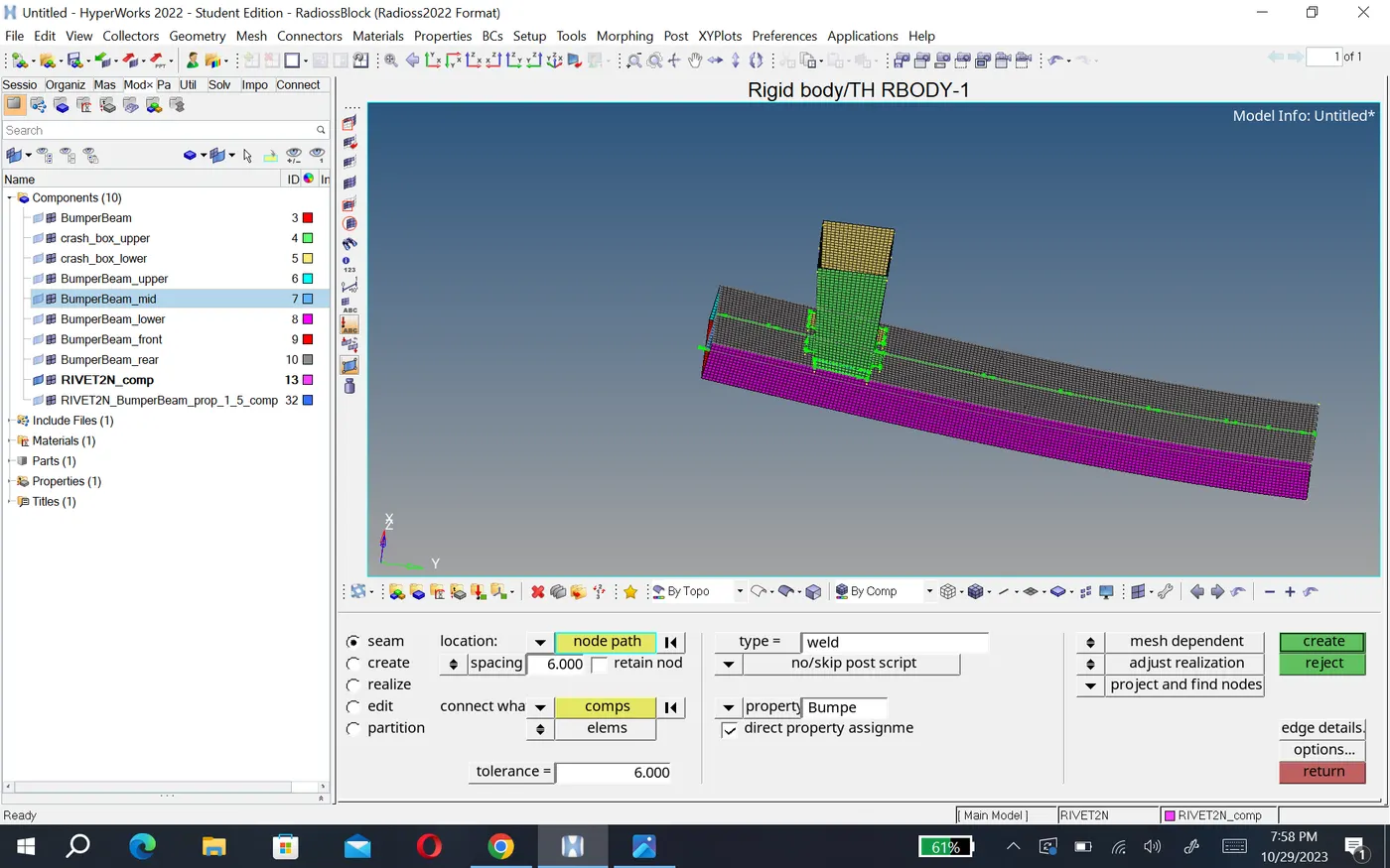
- there are different type of connection availables.apart from this we have chosen seam weld which is used to connect different material.
model2:- solve different cases on crash tube.
case 1:- Run the crash tube model as it is.
- After importing model, we need to simulate it without do any changes in this case.
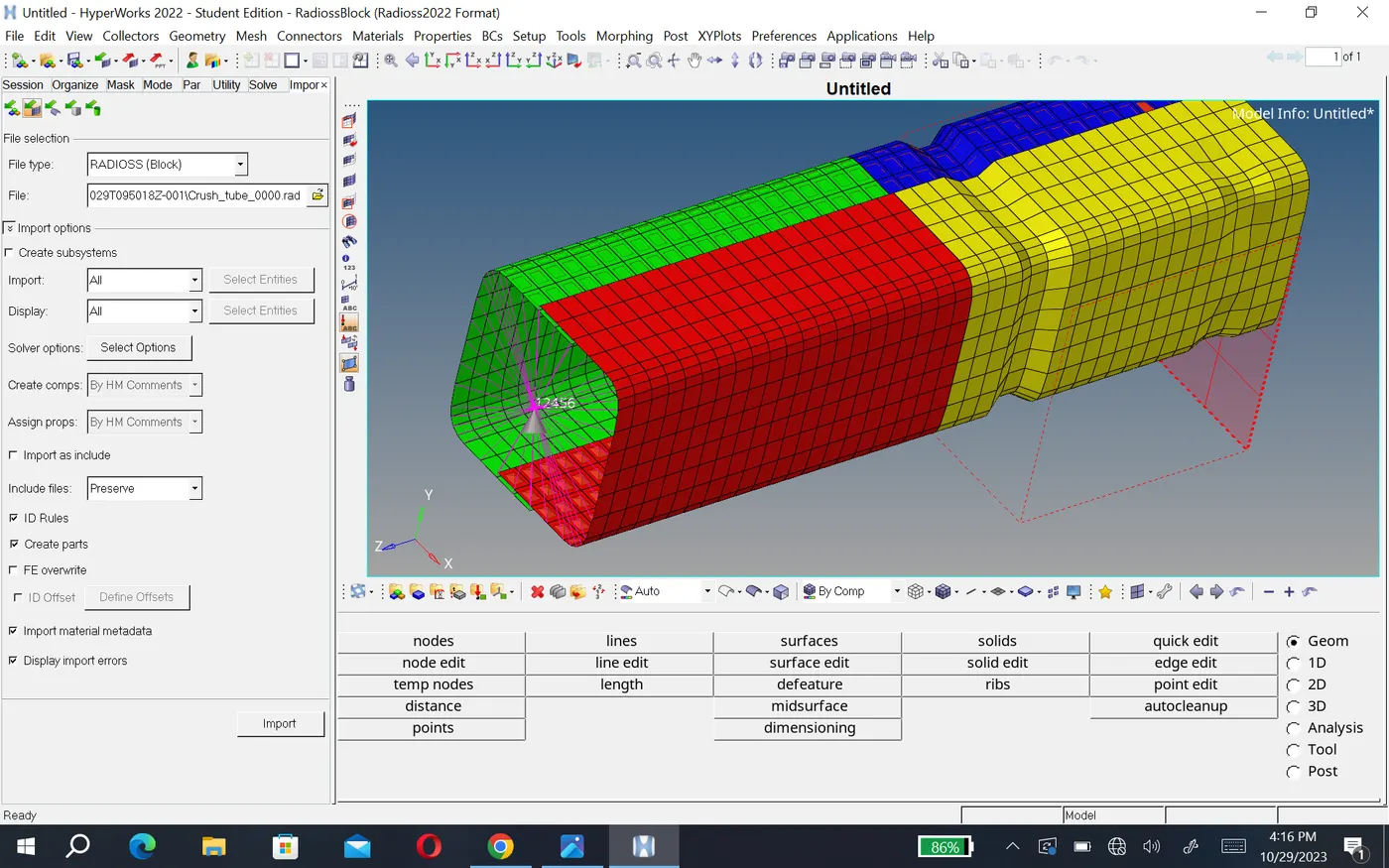
- so we go analysis tab go radioss.
- Here first save your model (_0000.rad). then check the include connectors and click on radioss to run that file.
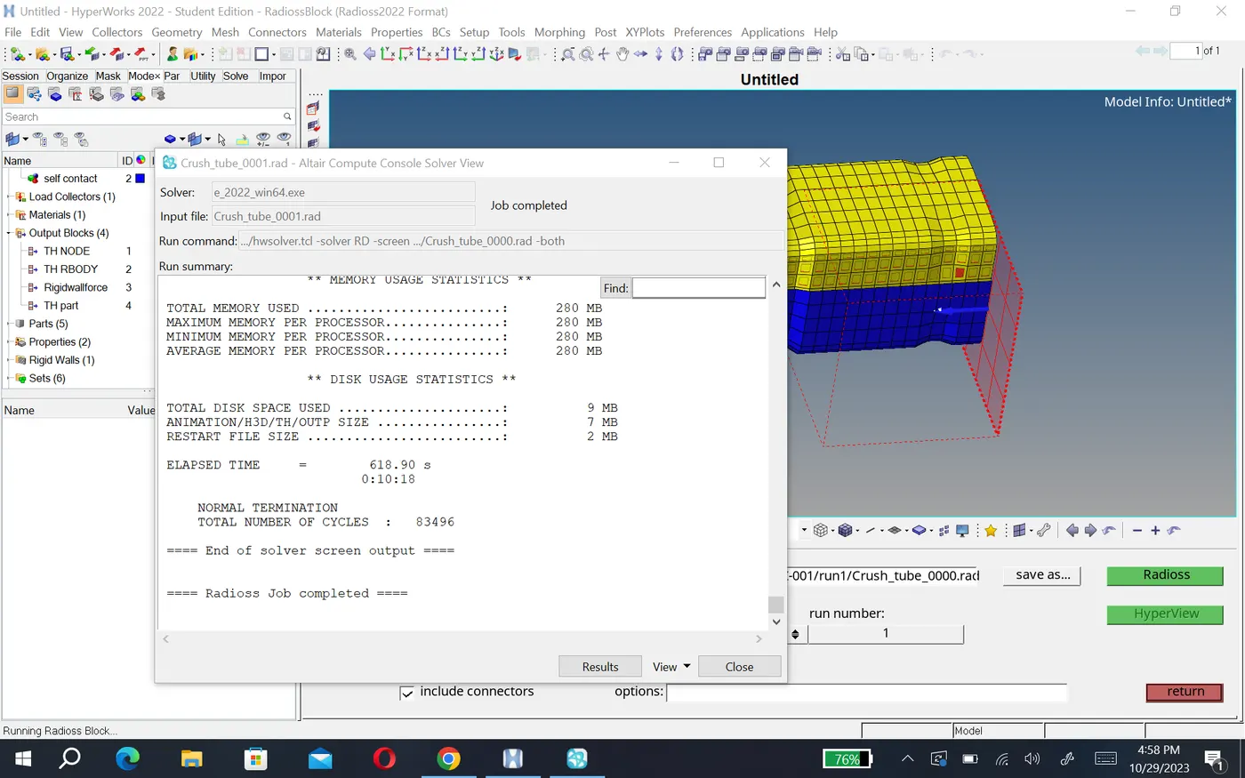
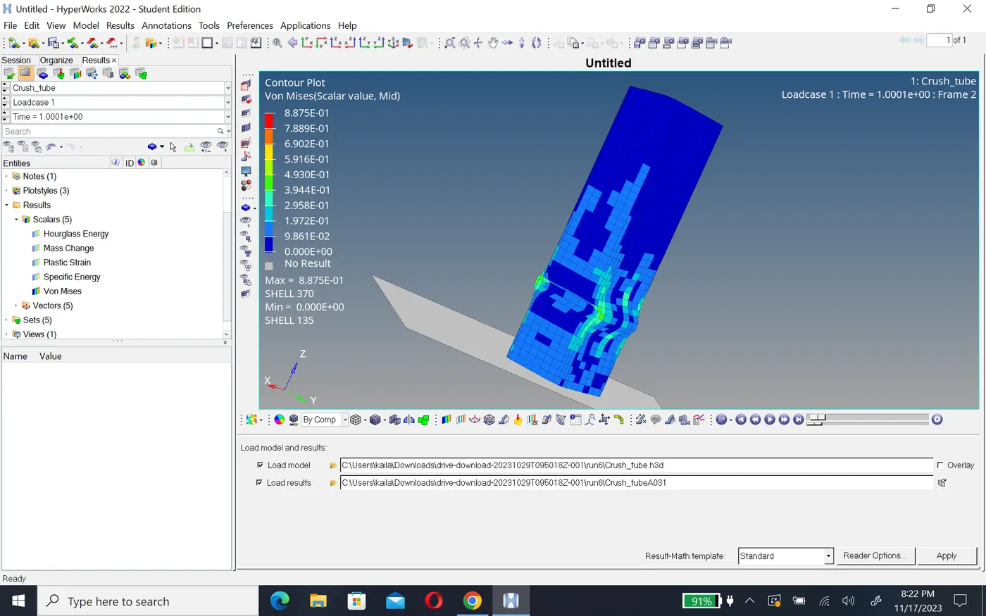
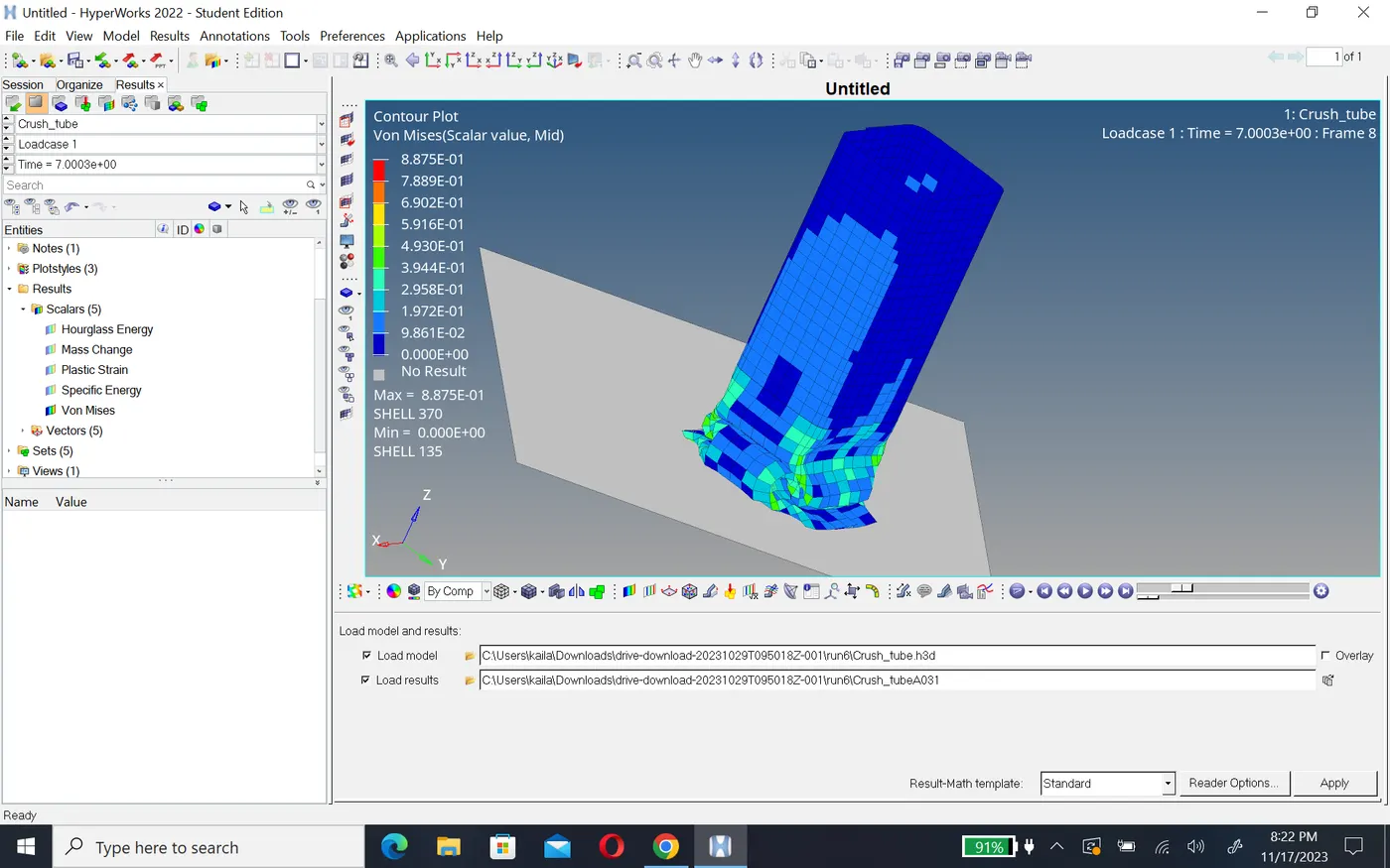
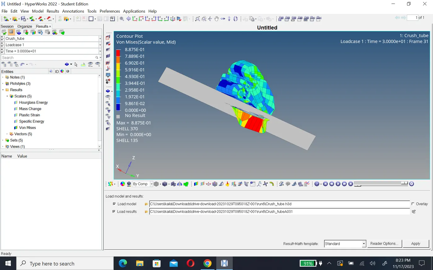
- For simulation we go hyperview and simulate the model.
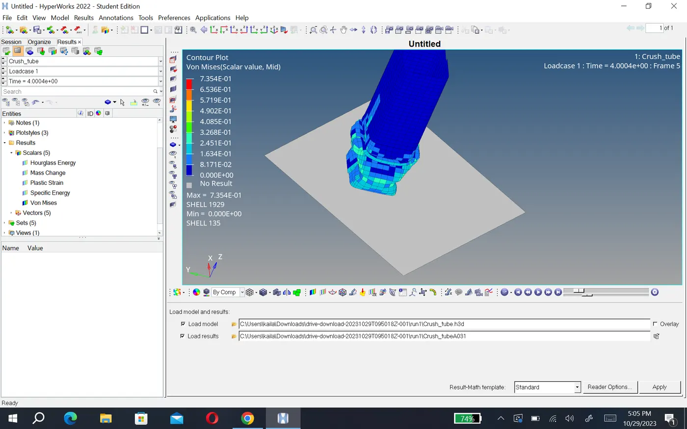
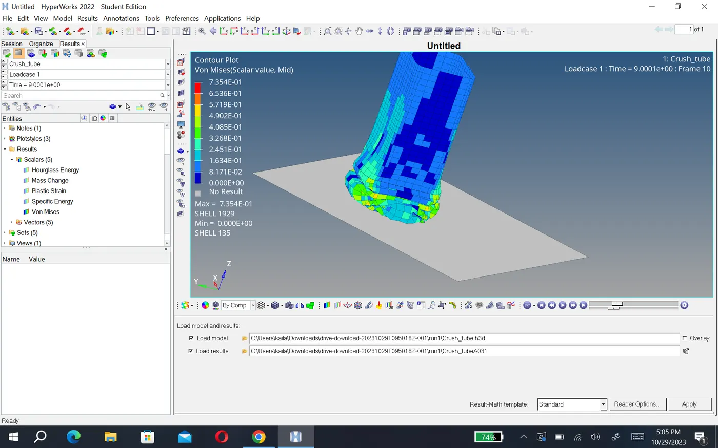
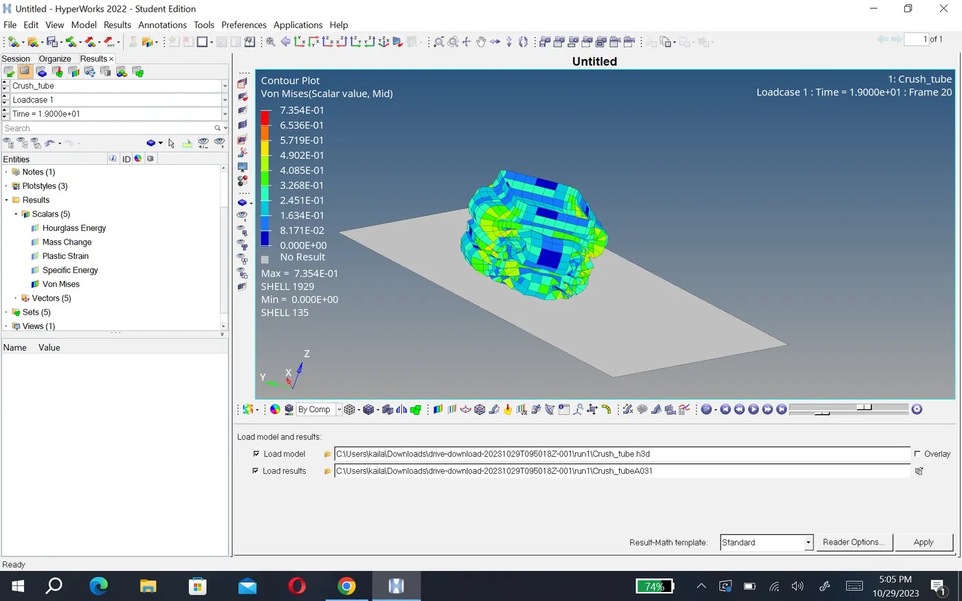
- for this component, the max von mises stress is created as 0.735N/mm2 and max contact force is created as 82N.
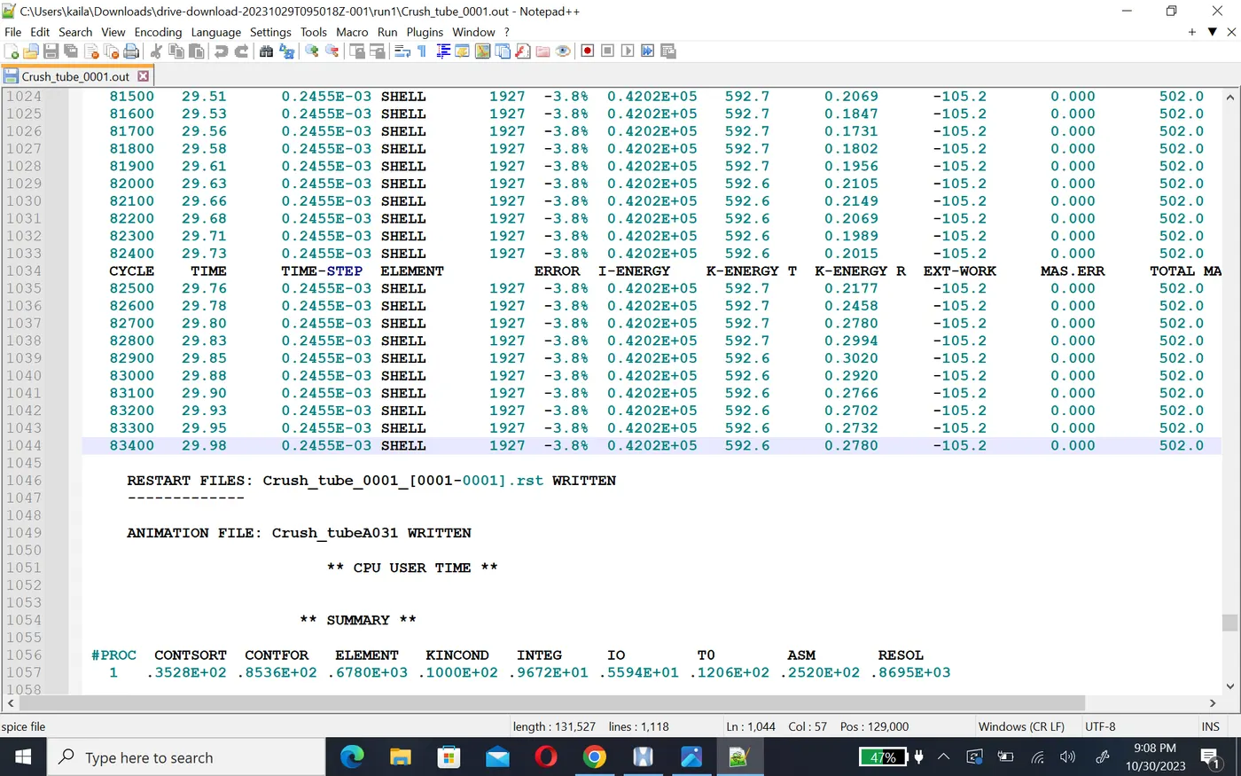
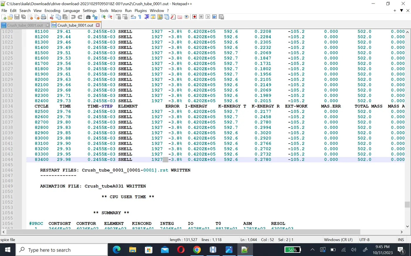
- Frome output file energy error is -3.8% which is less than -15% and mass error is 0. so we can accept the result and plote the graph by using hypergraph 2D.
- now open the hypergraph2D and open .T01 file to observing the energy and plote graph.
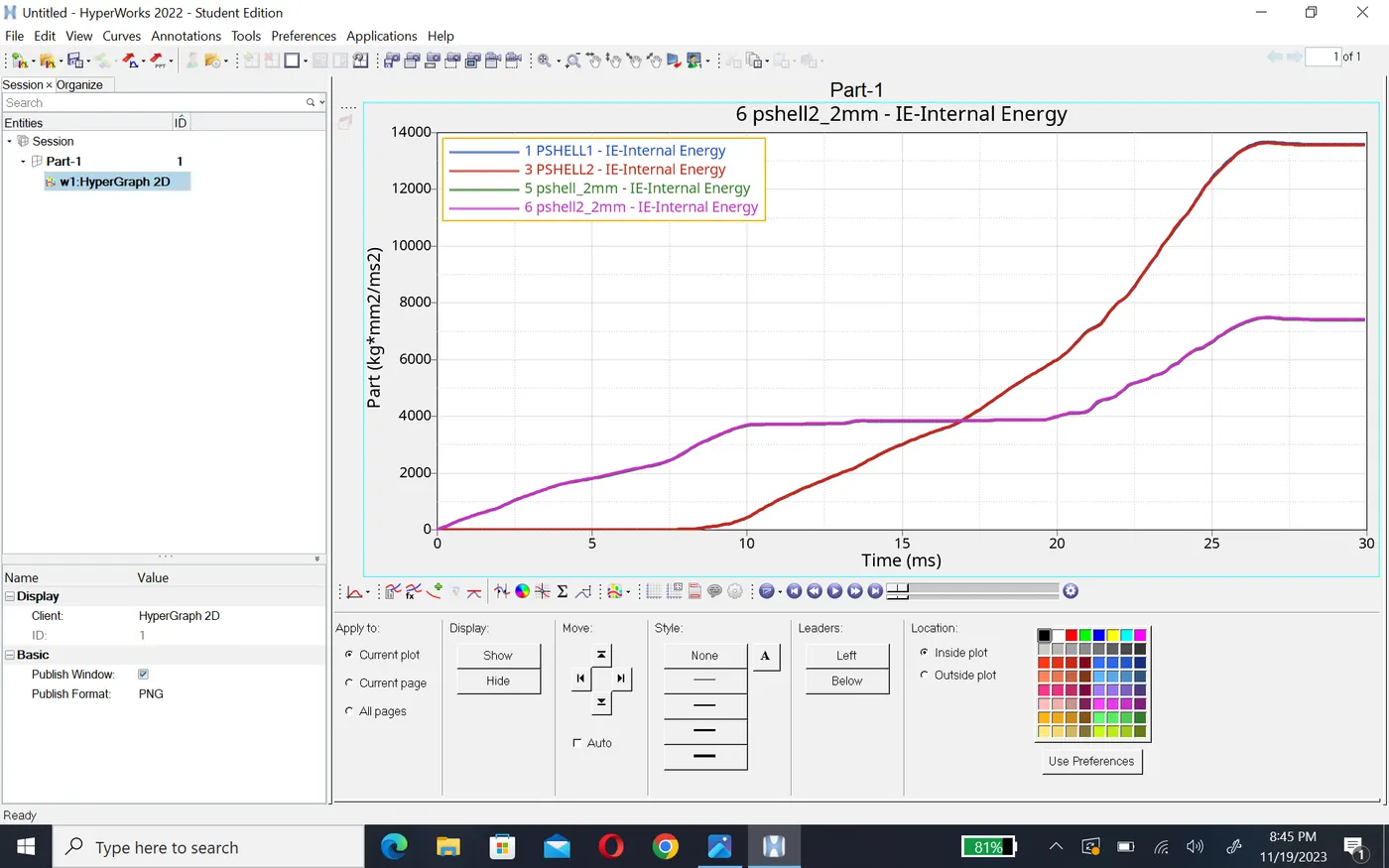
- Internal energy of component increase linearly at the beginning because it atteched to the rigid wall and deforme first at the notch area where as the stiffness is less at this component. and after deforme notches area plane surface become deformed because stiffness is higher as compare to notches area.
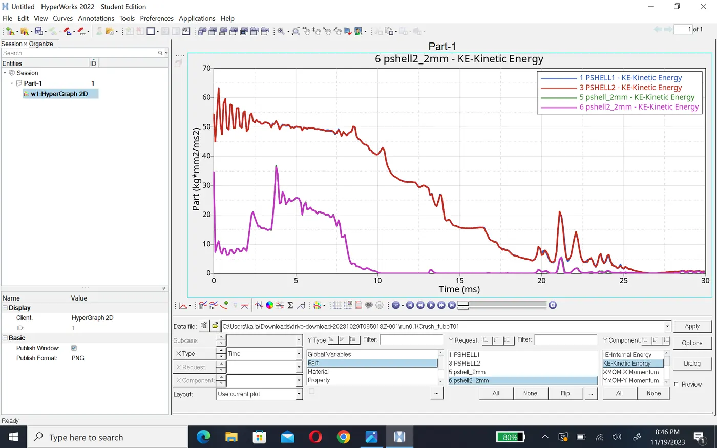
- Kinetic energy of this component is higher at the beginning as show in graph and it decrease gradualy after 25ms it become constant which means component no more deformation will occurs.
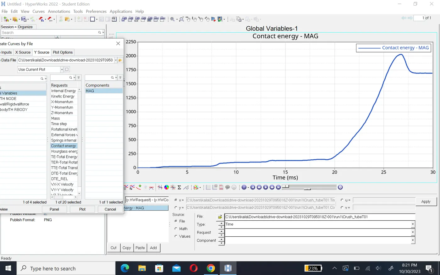
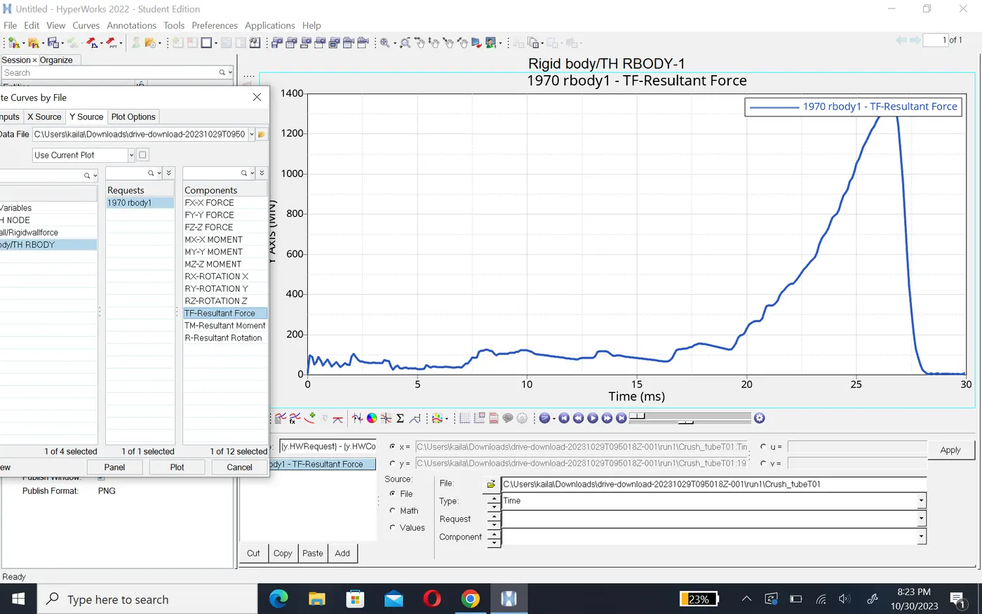
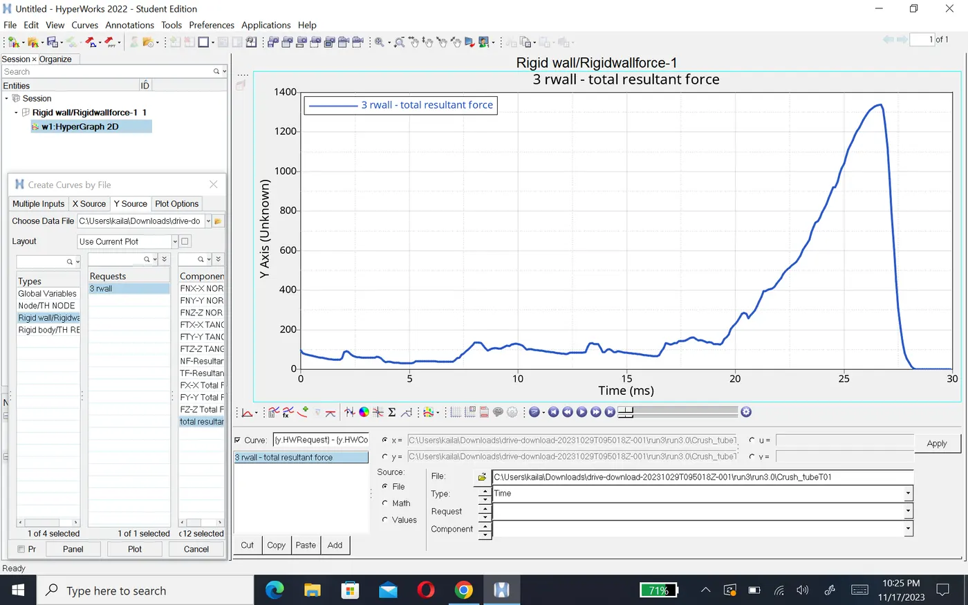
- contact energy of this component is varying at a vary small amount at the beginning and there is sudden peak formed because there is a large amount of energy developed at the and of deformation. The overall element are become compressed which will developed large force on the rigid wall around 1400N and energy create 2KJ.
Case 2- Change the Inacti=6 and run.
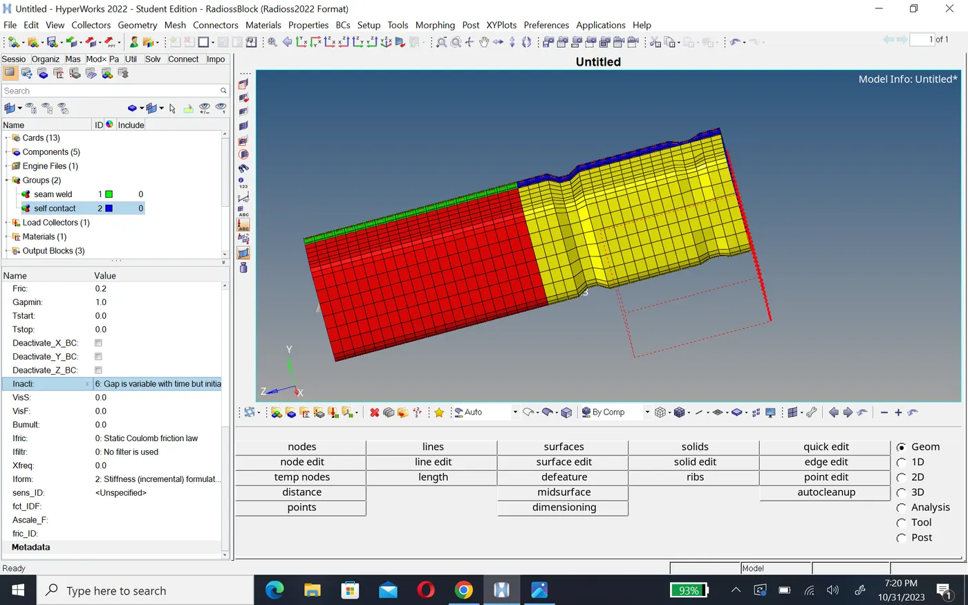
- in this case we change recommended property that used by type 7 contact interface inacti=6 as per problem statment and show in the fig.
- After change the parameters run the simulation with same steps to be carried out as per perivous case.
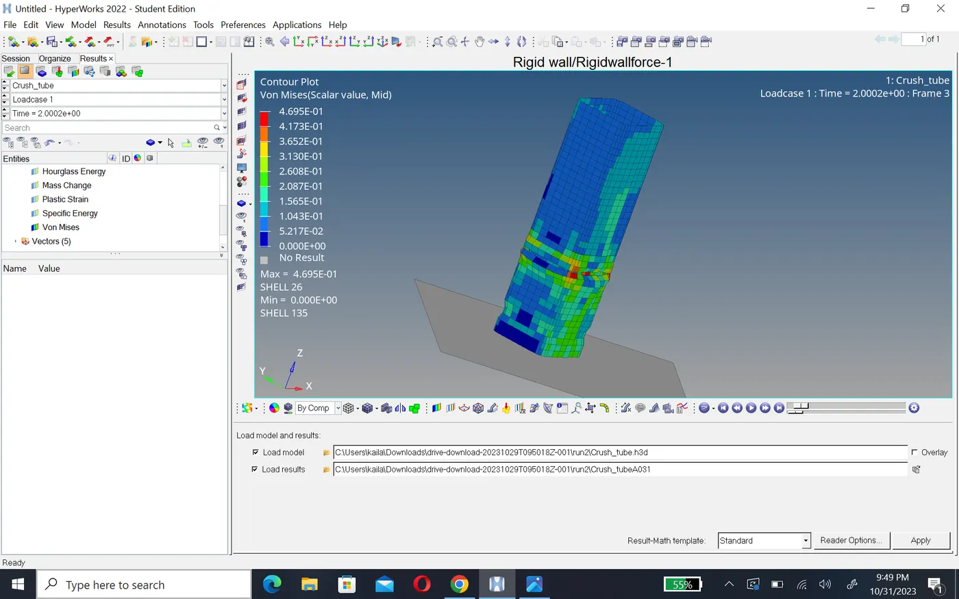
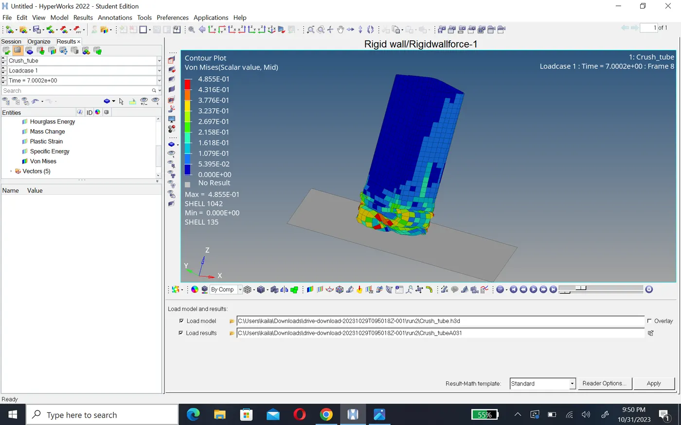
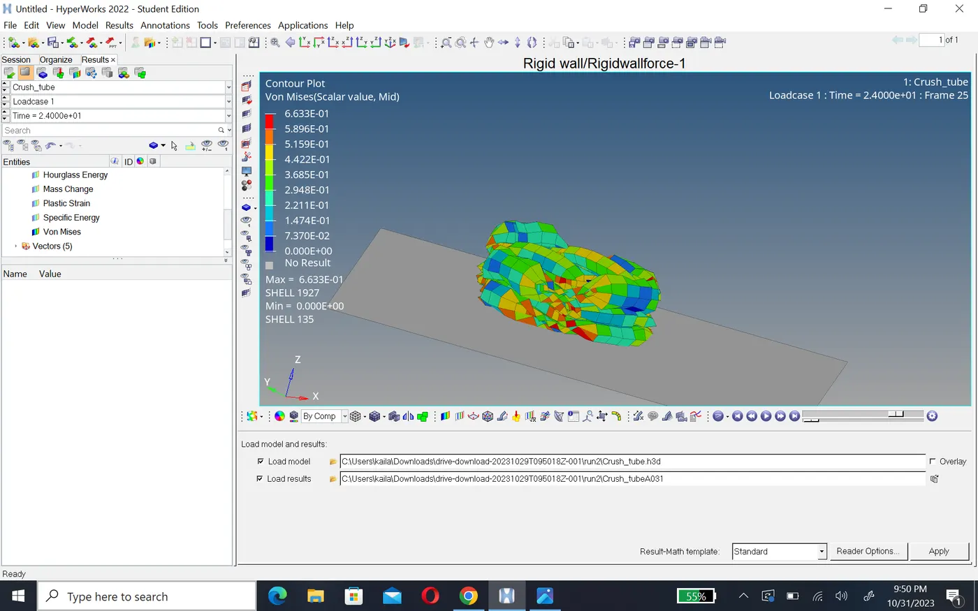
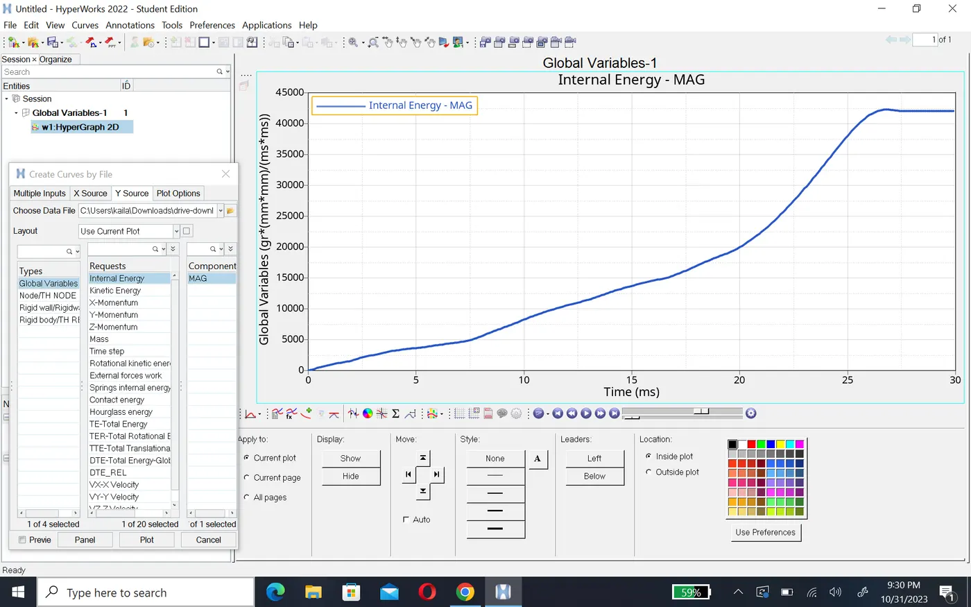
Internal energy of component increase form 0 to 44,403, at the beginning because it atteched to the rigid wall and deforme first at the notch area where as the stiffness is less at this component. and after deforme notches area plane surface become deformed because stiffness is higher as compare to notches area.
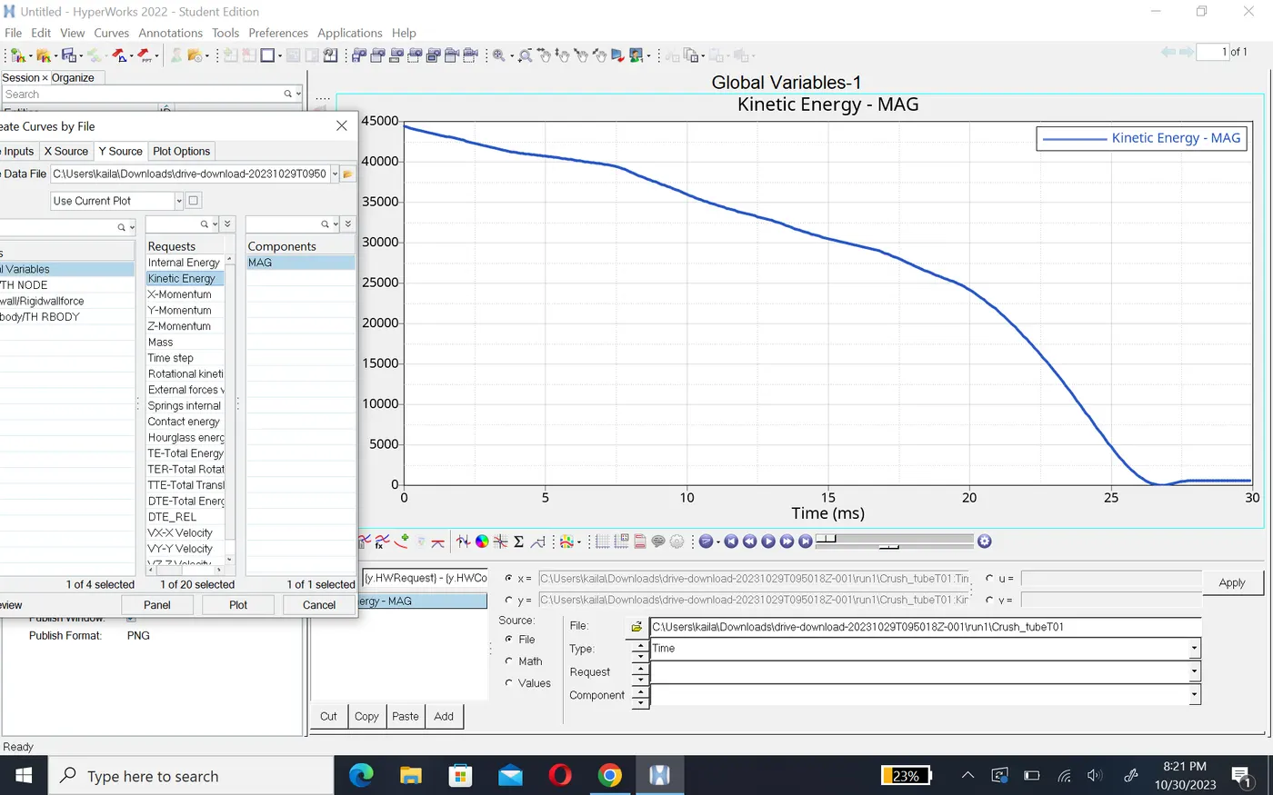
- Kinetic energy of this component is higher at the beginning as show in graph and it decrease gradualy after 25ms it completely deforme which means component no more deformation will occurs.
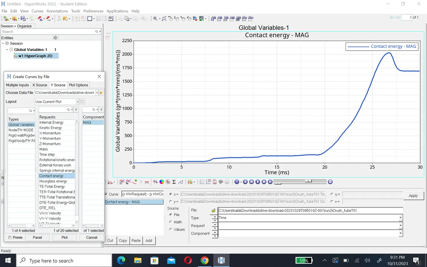
- contact energy of this component is varying at a vary small amount at the beginning and there is sudden peak formed because there is a large amount of energy developed at the and of deformation. The overall element are become compressed which will developed large force on the rigid wall around 1350N and energy created 2.1kj.
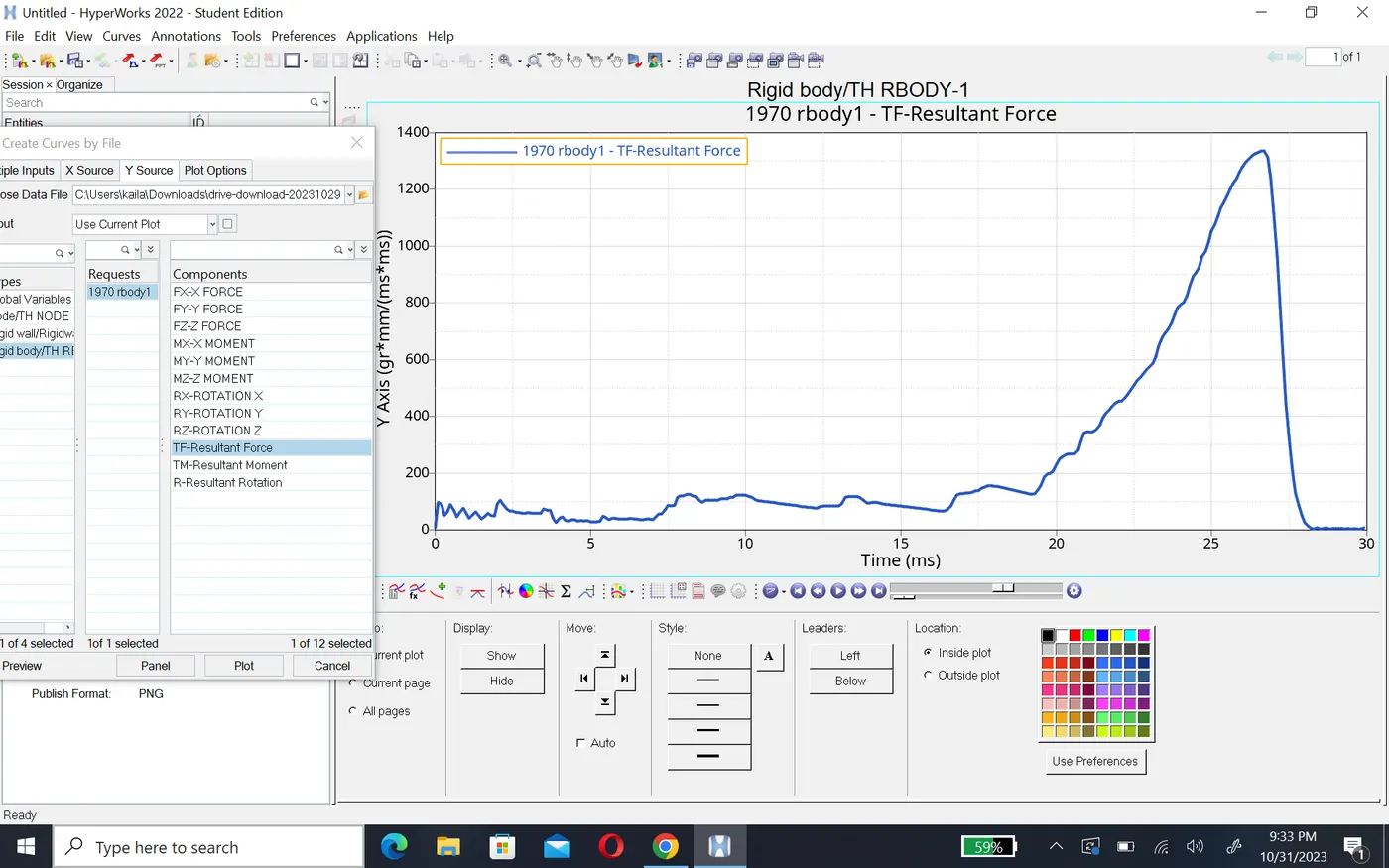
Case 3:- Create the type 11 contact and run.
- In this case after importing model we have to change card image as type 11 contact as per problem statment.
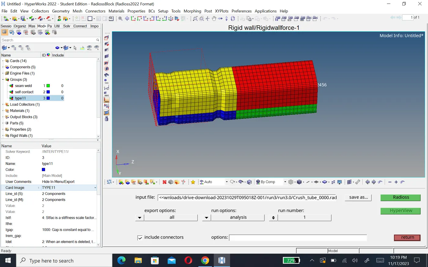
- Type 11 take into account of the connections made by the edges of the slave segment to the edges of the master segment and hence improves the accuracy of the reactive forces calculation.
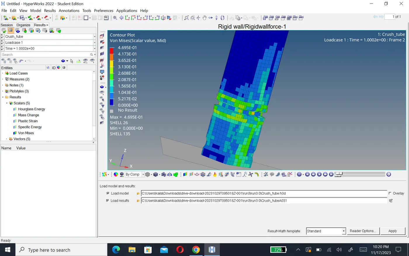
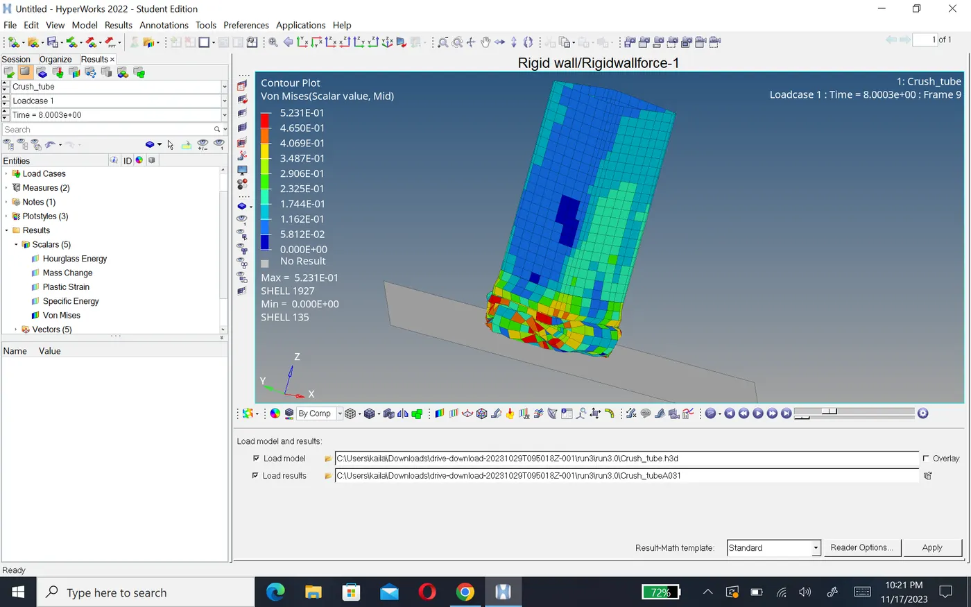
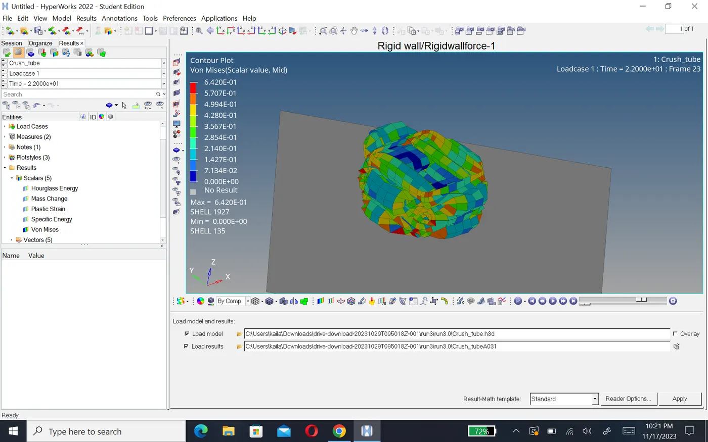
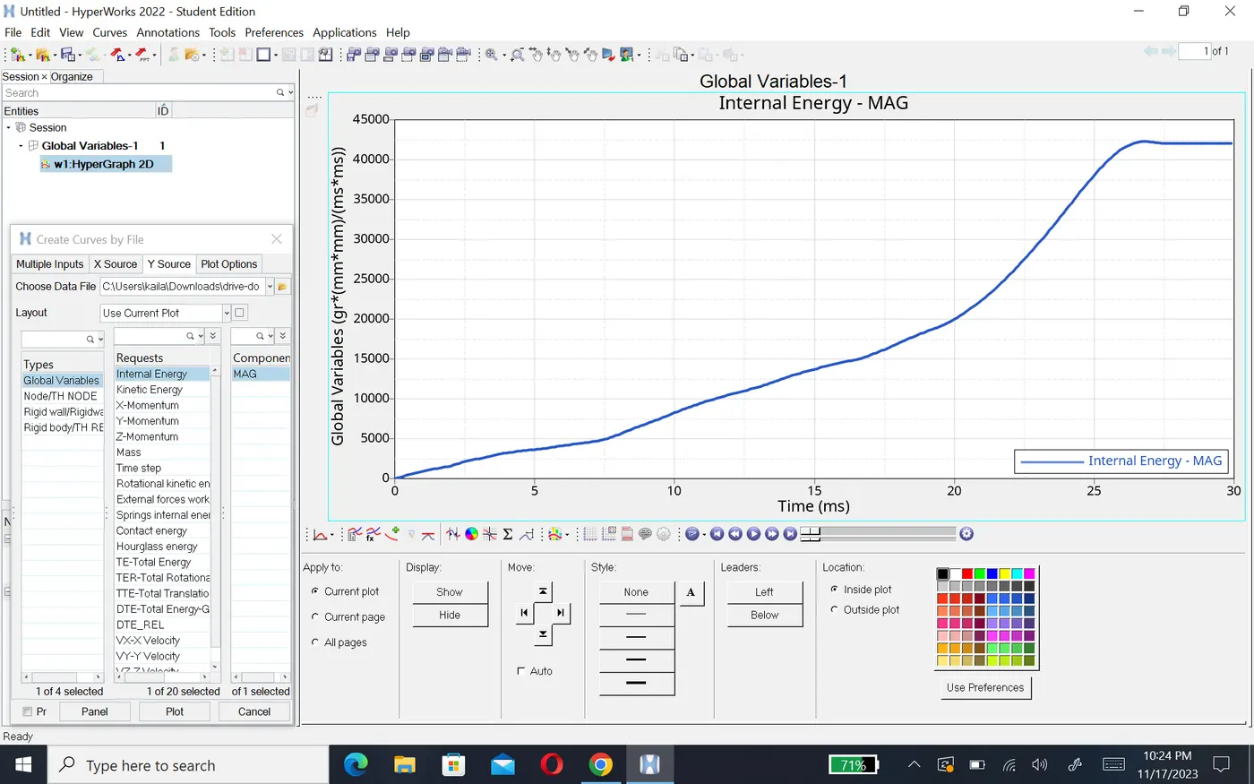
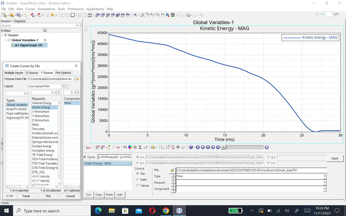
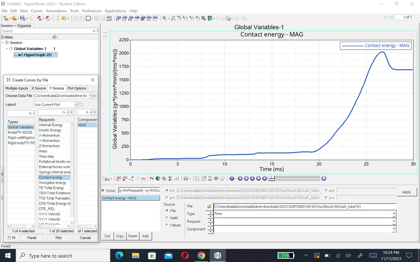
- Above three graph are same as case1,2 but rigid wall force stare from 100 and it varying, after 20ms it increase till 1375N and energy create 2.1KJ.
Case 4:-Remove both notches and remove boundary condition on rigid body node then run.
- In this case we need to delete notches and makes it into a plane mesh.
- To delete notche, go to the tools panel and select delete option>select the elements to delete>click on delete entity.
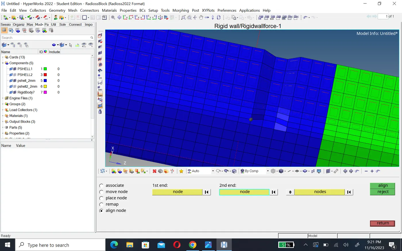
- Now to create a plane surface go to the 2D panel,select ruled option>select the first node list and second node list>click create>the mesh is created given the element length 6mm>click recalculate>click mesh.
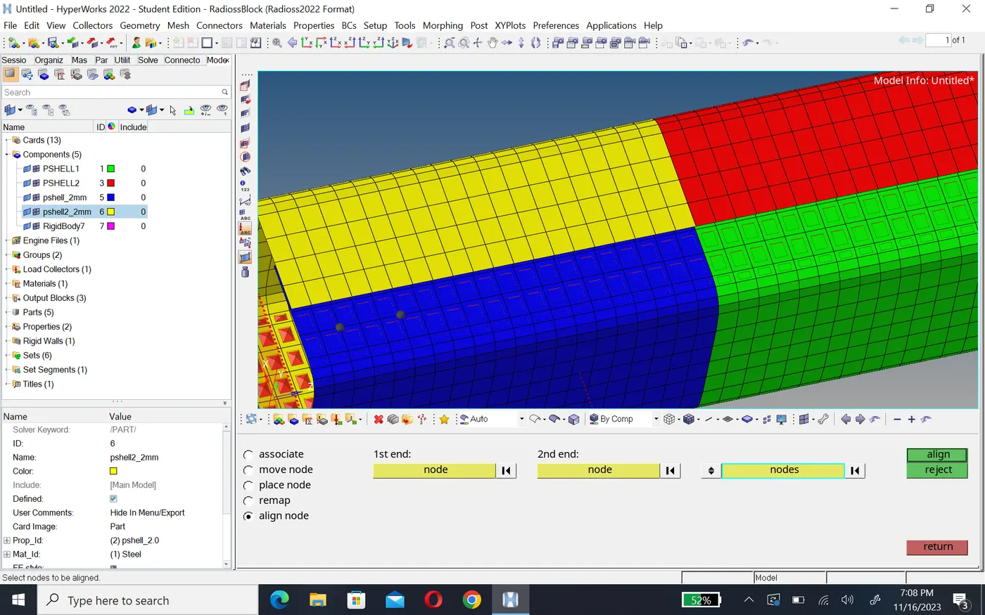
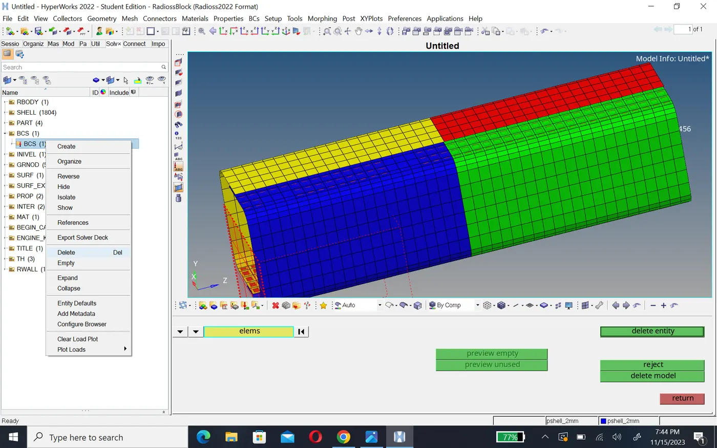
- Now go to solver deck and delete boundary condition.
- To siumulate the model,go to the analysis panel, select the radioss option and run it.
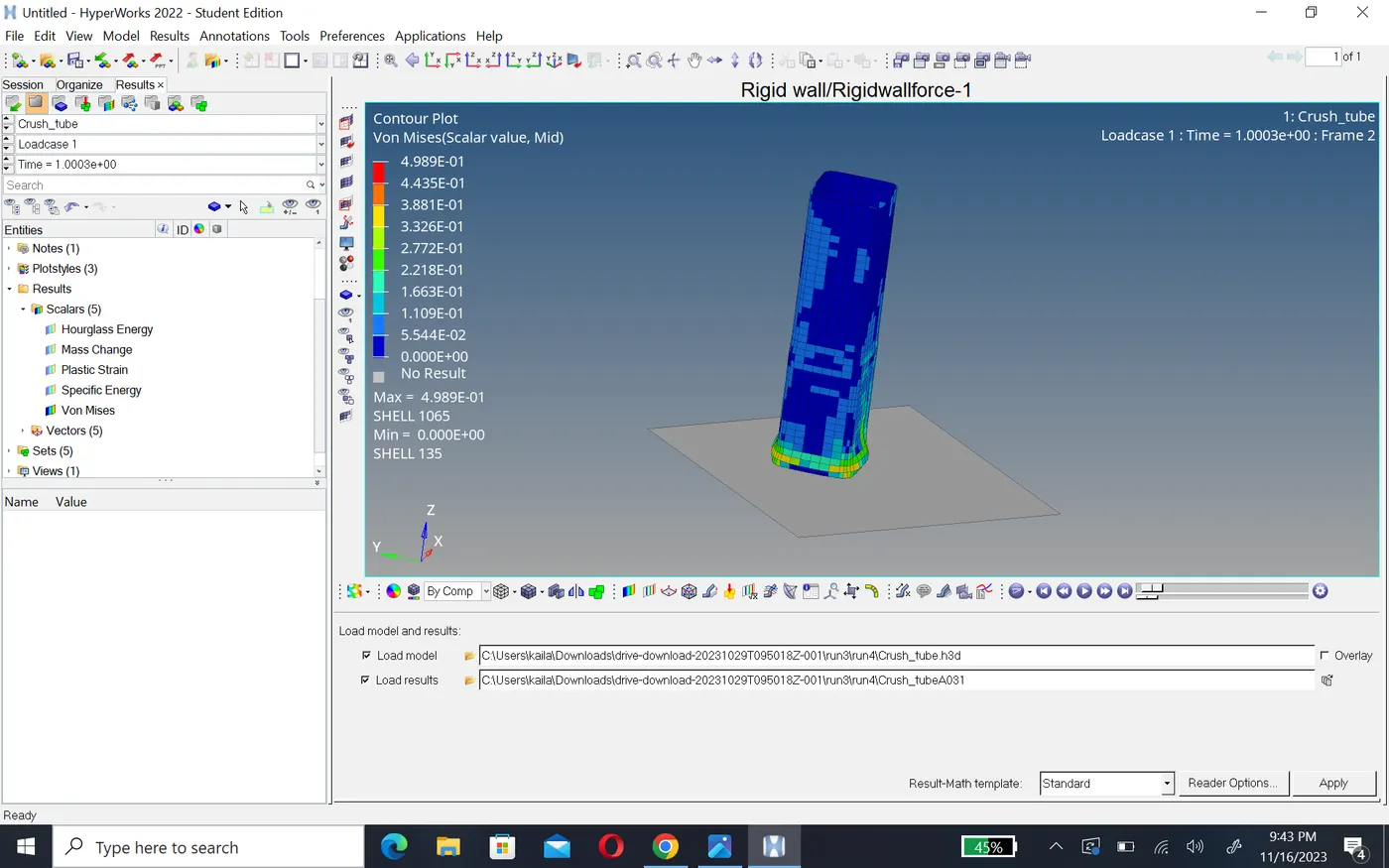
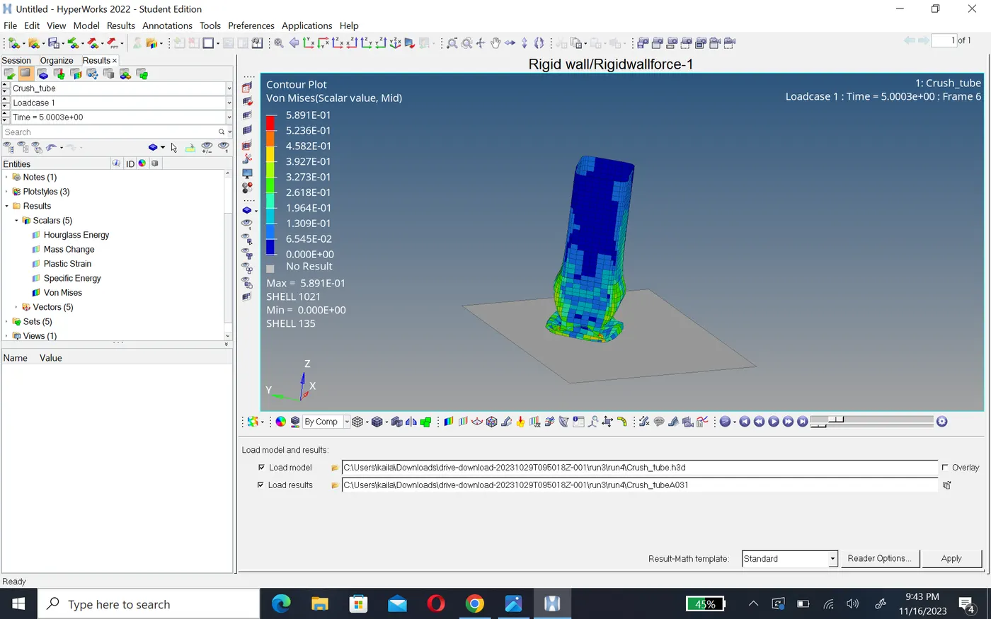
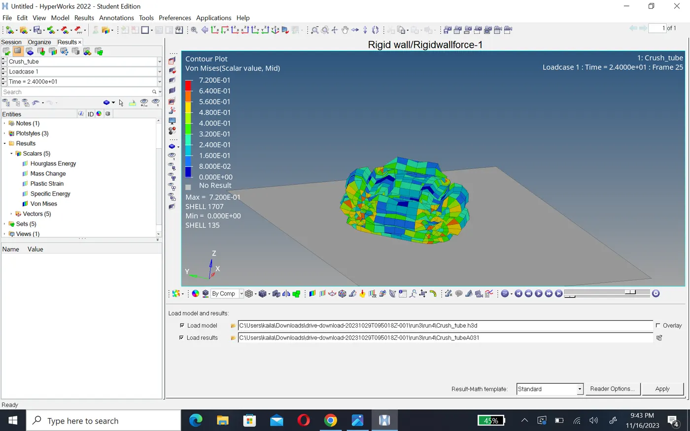
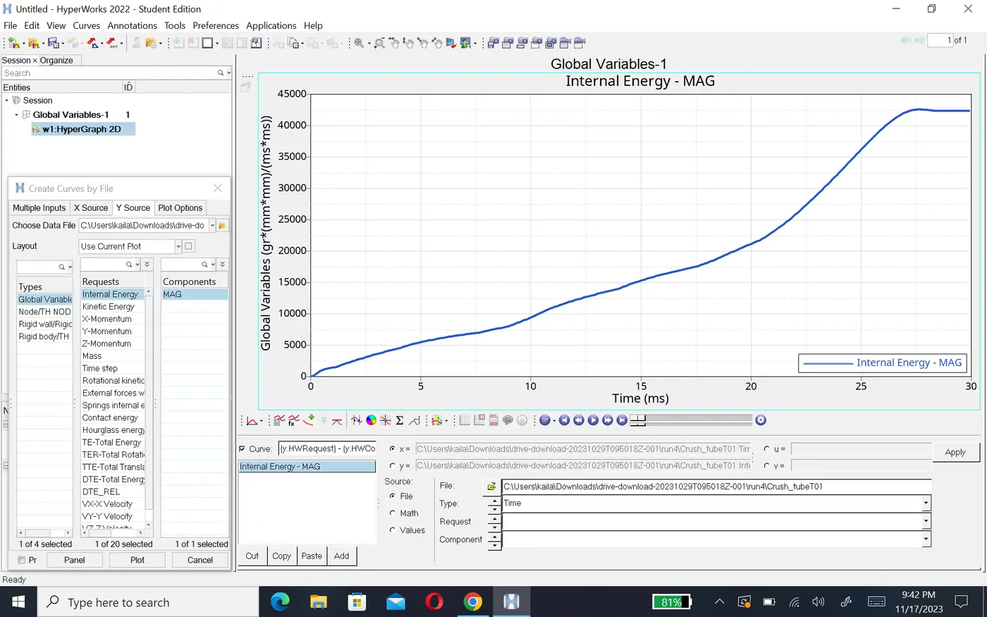
- Internal energy of this component increase forme zero at beginning and increase till 44405,after that it become constant.
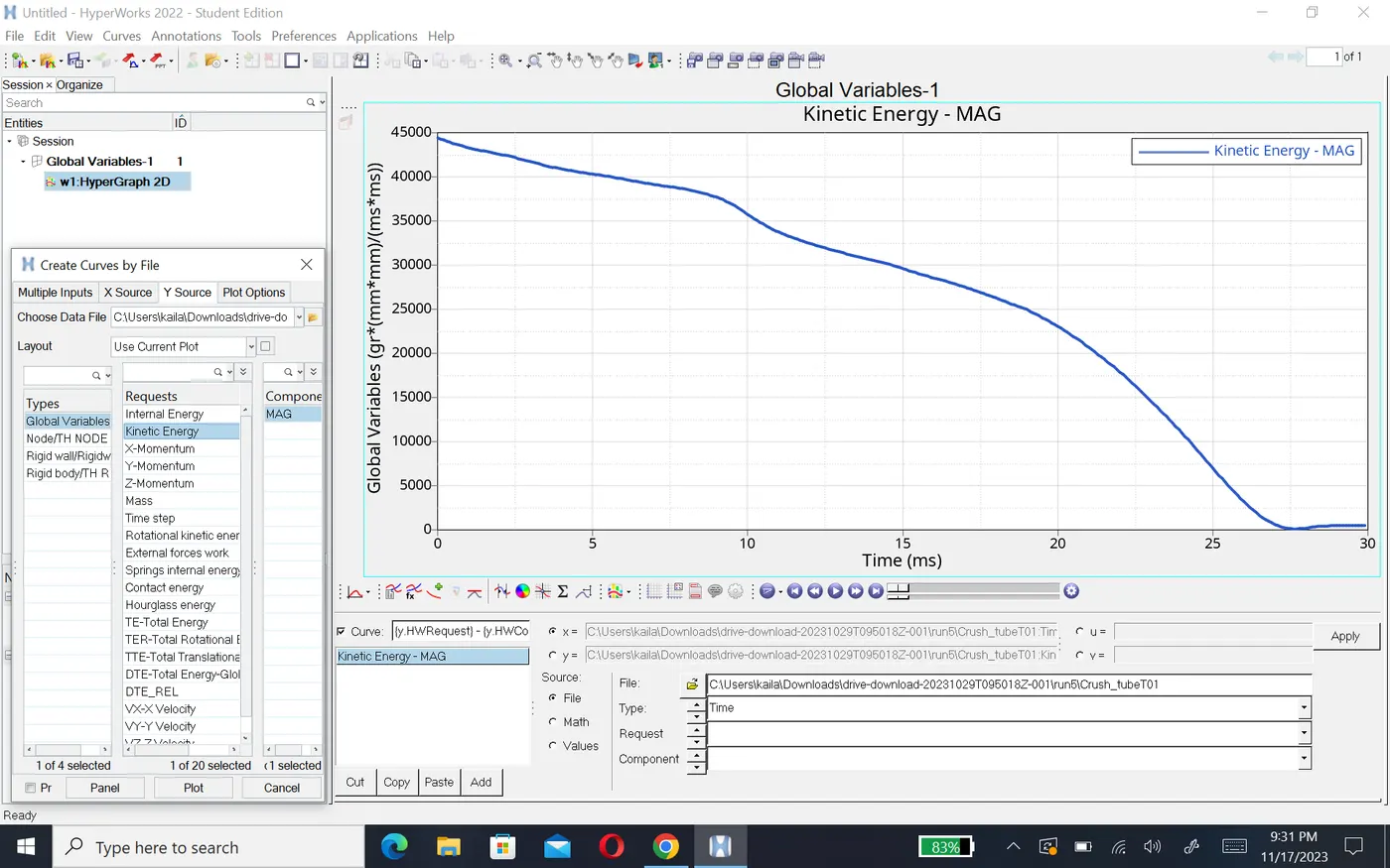
- kinetic energy after remove notches stiffness of the component increase therefore kinetic energy of this componenet is higher at beginning but it decrease gradualy after 25ms it become zero with -13.3m/s velocity.
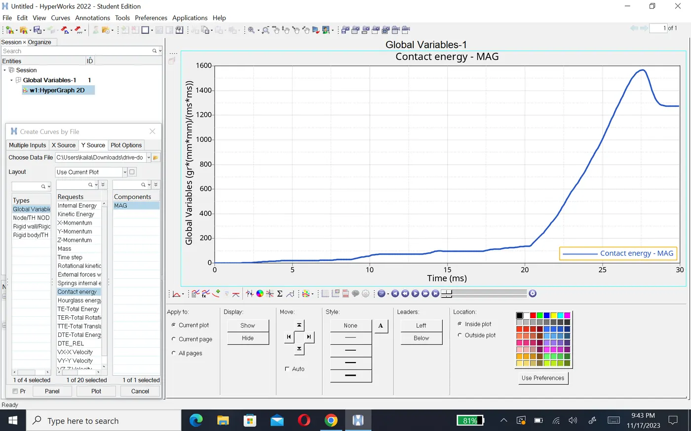
- After removeing notch contect energy will decrease as compare to above cases it increase till 1600. here rigid wall force increase 1200N and energy create 1.5KJ.
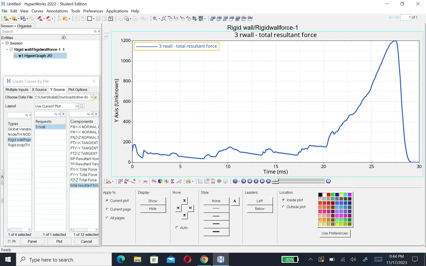
Case5:- a new notch in the middle ,select the whole section and run.
- In this case, the model is imported and run the simulation with recommended properties where there is notech presented on the middle surface and also the boundary conditions are removed. the notch is created with the magnitude or depth of 3mm.the type 11 contact interface is used with recommended property as show in figure.
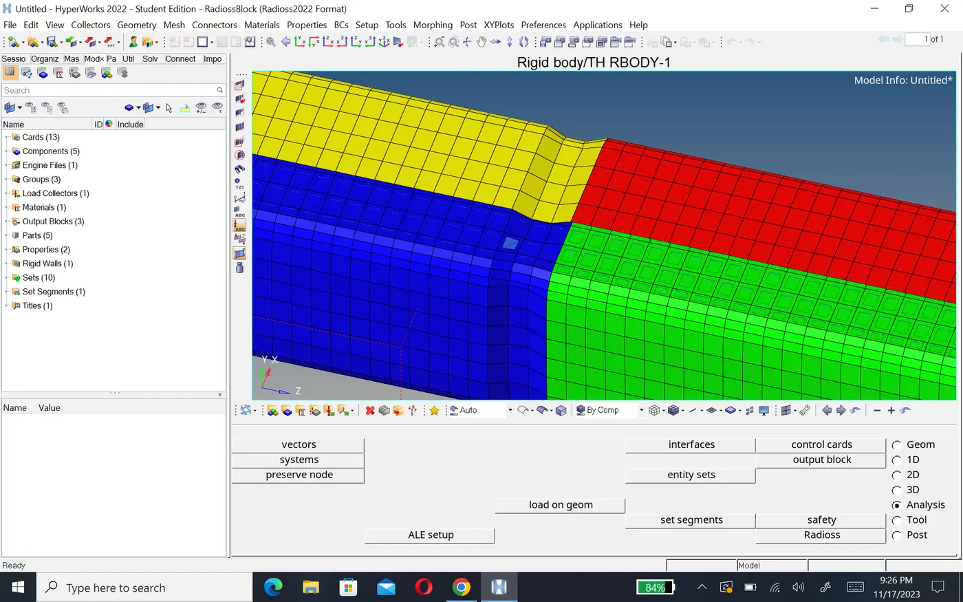
- Now to simulate the model as per the privious cases.
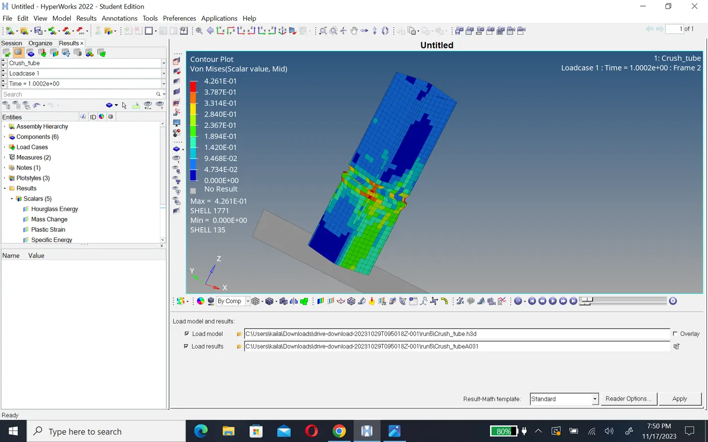
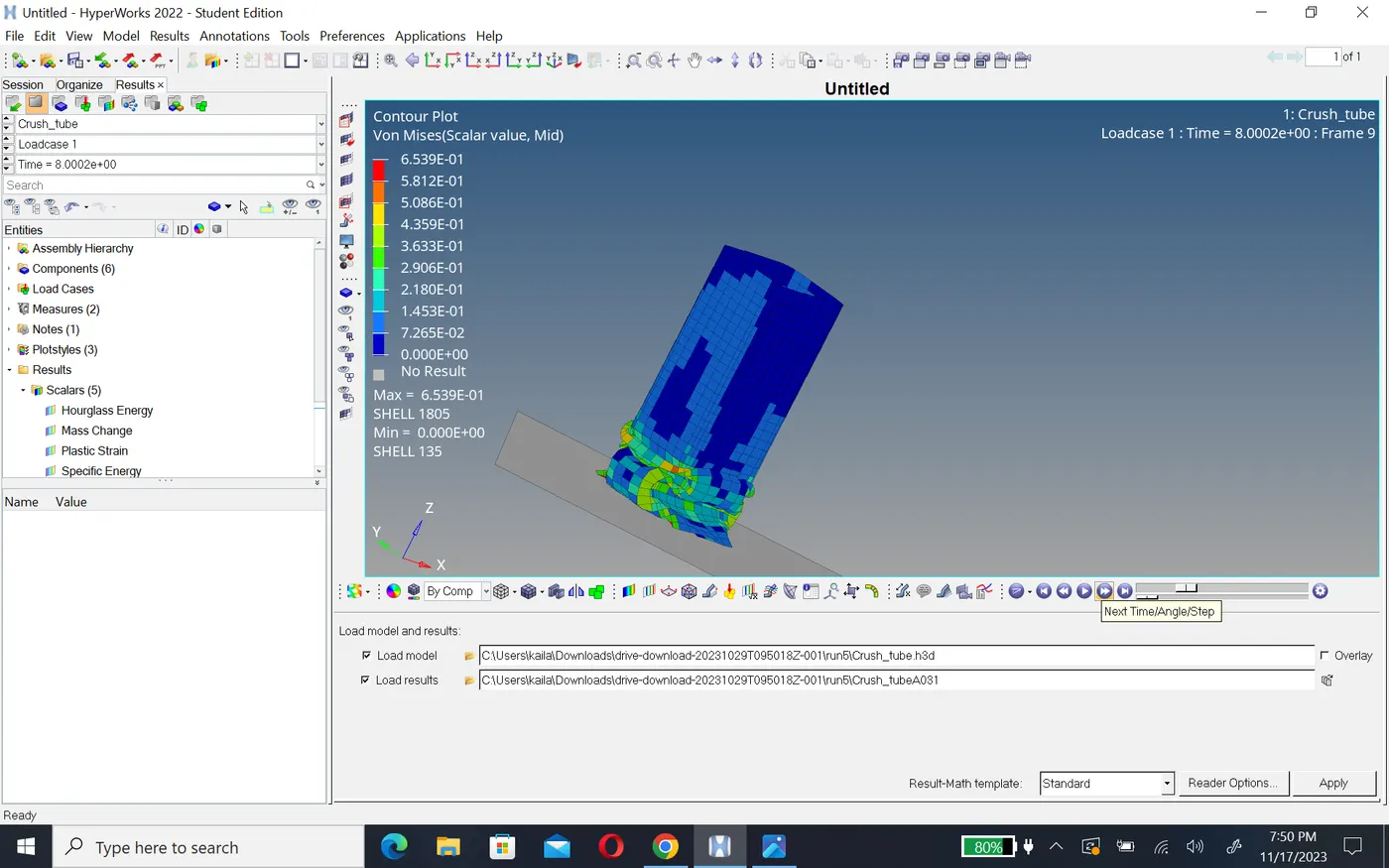
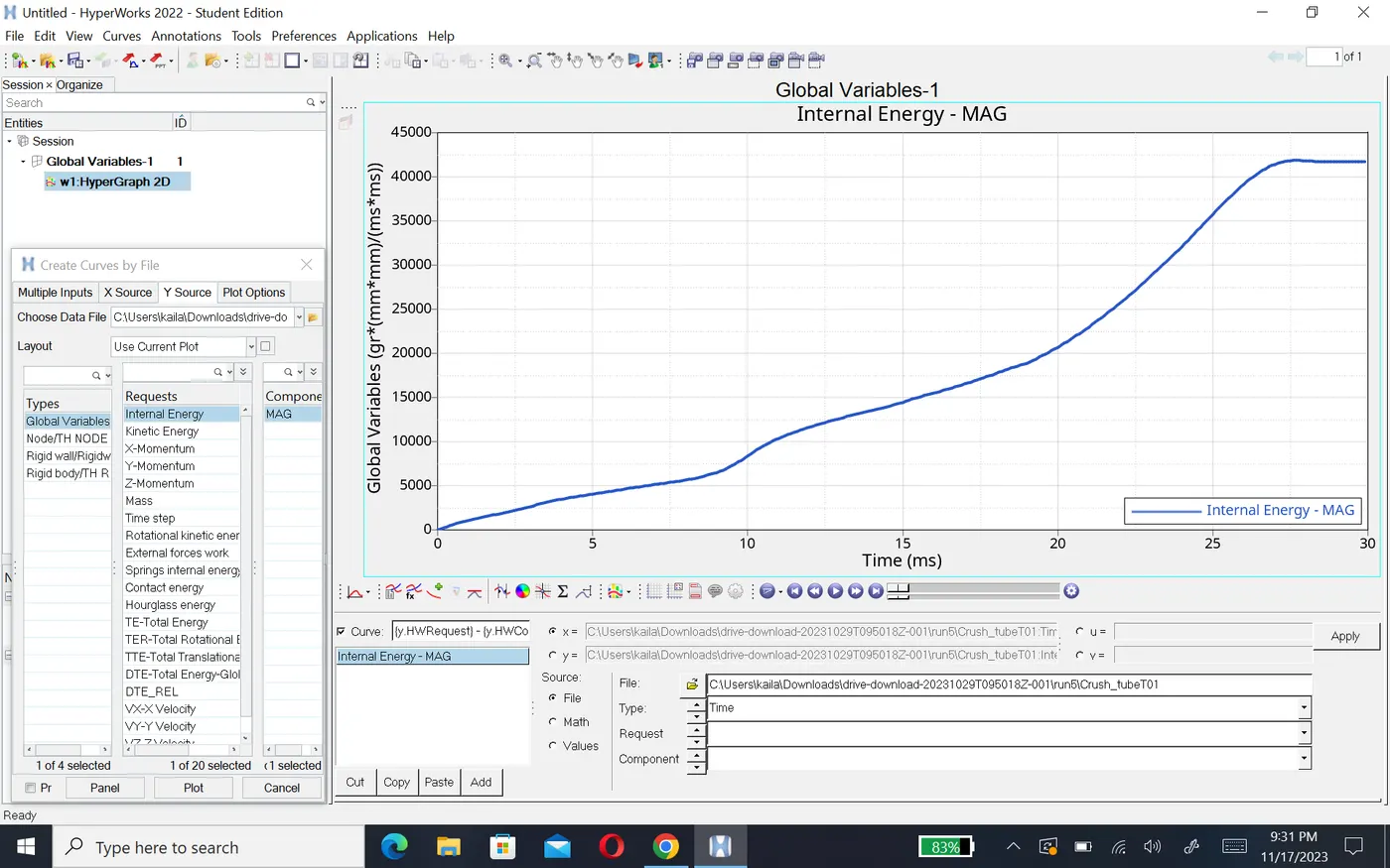
- internal energy and kinetic energe same above cases.
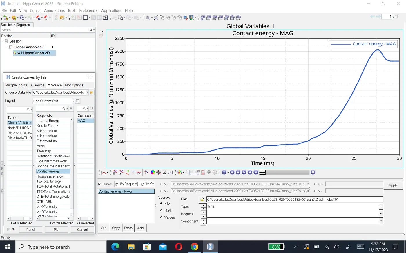
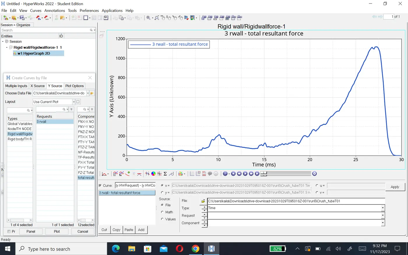
- After creating notch in the middel of the component contect energy will increase till 2100. here rigid wall force decrease 1100N and energy create 2.1KJ.
Case 6:-Create a new notch with nodes only from opposing 2 faces and run.
- In the case, a notch should be created at the same places in the opposite direction.
- Again, to create notch the translate option is used.
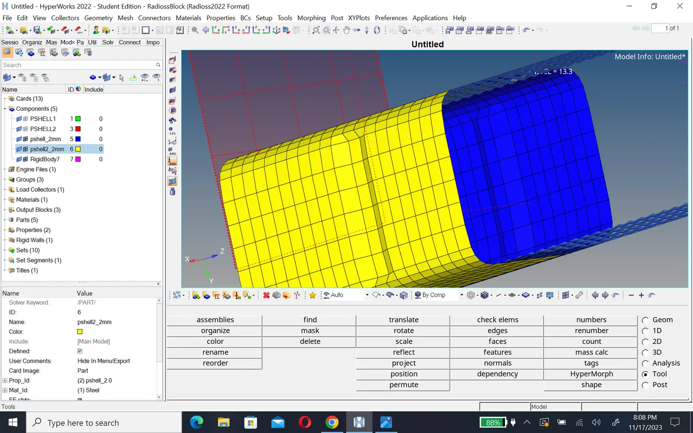
- go to the toole panel select translate option > select the nodes to translate > select the orientation of the elements > give magnitude as 3 then notch is created.
- Now run the simulation as per previous cases.
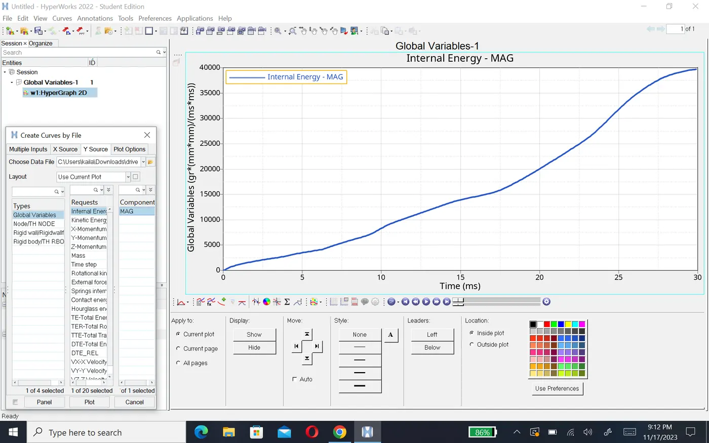
- in thise case internal energy start frome 0 and increase till 40KN and kinetic energy started from 45kN and decrease gradualy it will become zero at 30ms.
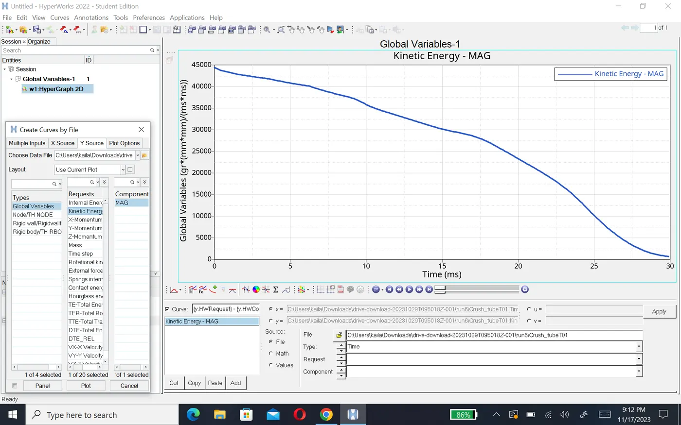
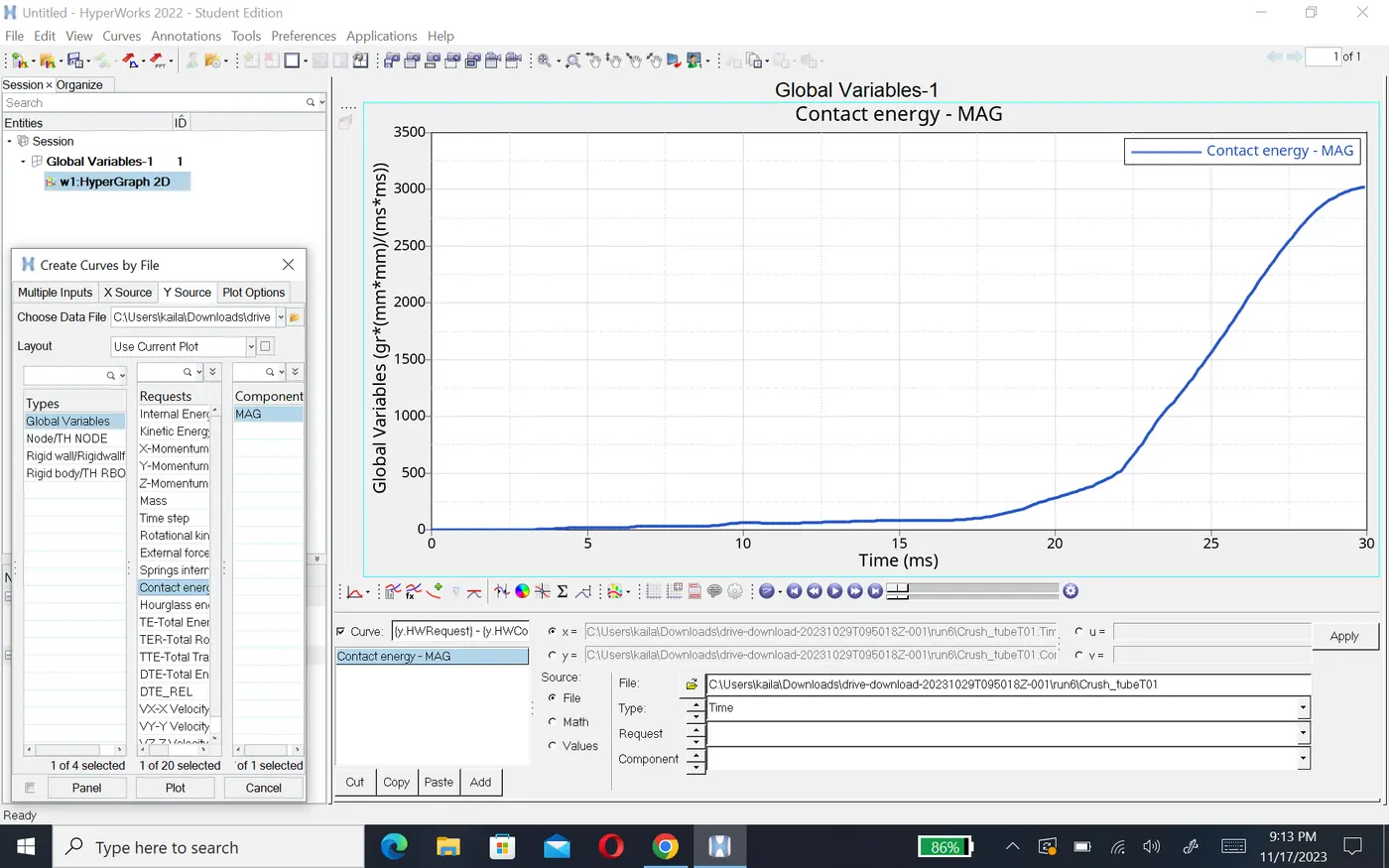
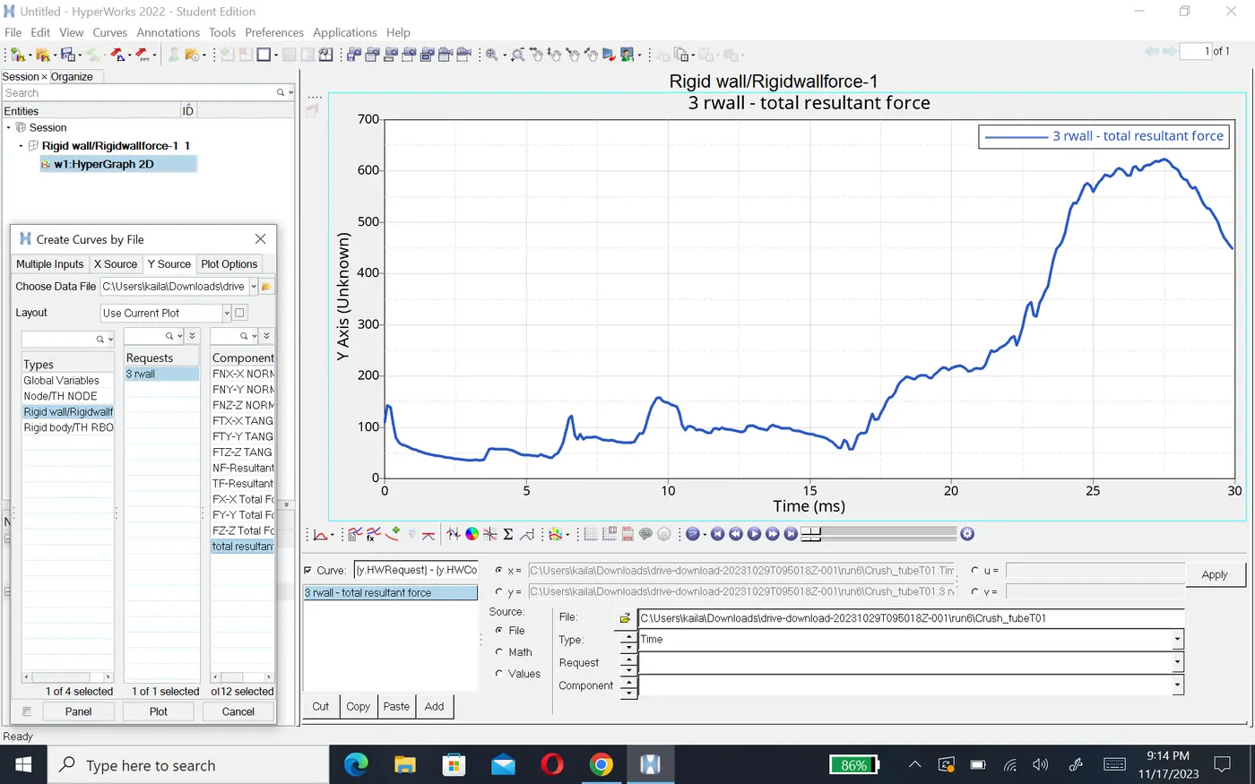
- After creating notch in the opposit surface of the component contect energy will increase till 30KN. here rigid wall force decrease 600N and energy create 3KJ.
Results:-
- comparison of energy error mass error,max contact force,rigid wall force and internal energy show in table given below.
| case no | Energy error % | mass error % | Max contact force N | Max rigid wall force | Max contact energy kj | Reason |
| 1 | -3.8% | 0 | 85.3 | 1400 | 2 | Node to surface contact type 7 |
|
2 |
-3.8 | 0 | 60.3 | 1350 | 2.1 | No initial penetrations found |
| 3 | -3.9% | 0 | 100.1 | 1375 | 2.1 | Type 11 edge to edge contact |
| 4 | -3.0% | 0 | 37.1 | 1200 | 1.5 | no boundery condition |
| 5 | -4.1% | 0 | 101.9 | 1100 | 2.1 | ablity to absorb increased due to middle notch |
| 6 | -7.0% | 0 | 46.4 | 600 | 3 | due to opposing notches |
- The change in the internal energy is due to the notches.with removal notches internal energy decrease and reduce energy error.
- The notch area have high stresses and deforme first. At the plane surface where the notch are remove the stress level are low. Hence, through the remove notches from body ,we can able to reduce the stresses acting on the body.
Conclusion:-
- All cases of crase tube have been simulated and results are compared using various energies point.