Assignment 5-RADIOSS Interfaces & Study of Effect of Notches Challenge
Assignment 5-RADIOSS Interfaces & Study of Effect of Notches Challenge
Aim :- To Create the mesh for bumper assembly, mesh size should be 6mm and simulate the given model with seven different cases in radios as per problem statement and compare it using various graphs.
Problem statement :-
Questions:
- Create the mesh for bumper assembly,mesh size should be 6mm.
- Run the crash tube model as it is.
- Change the Inacti=6 and run.
- Create the type 11 contact and run.
- Remove both notches and remove boundary condition on rigid body node then run.
- Create a new notch in the middle ,select the whole section and run.
- Create a new notch with nodes only from opposing 2 faces and run.
Note:
- Plot RWALL forces, contact forces, internal energy and Create TH/PART for all parts and compare results for all cases.
- Comment your thought on why there is a change in the internal energies.
- How does the notch affect the results?
- Plot energies and note any difference.
Solution :-
M1 :- Meshing of bumper assembly
Steps followed :
Import given model into hypermesh
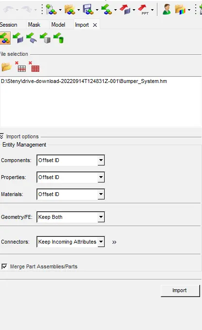
click import
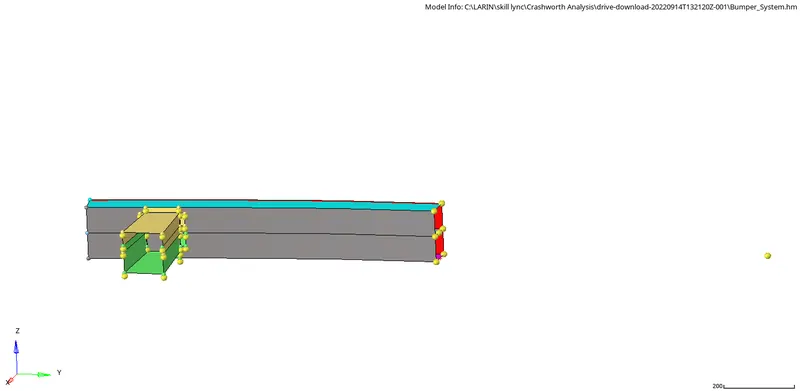
Clean the geometry
click f11 or go for auto cleanup options
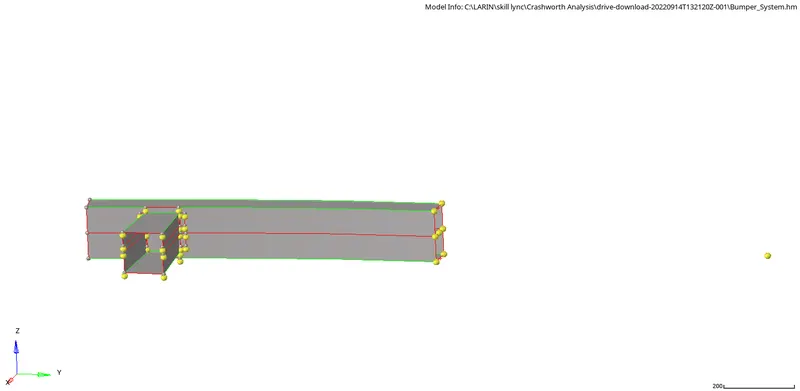
Assign quality parameters
- To give the Criteria, Click on the Preferences in the Standard Menu bar >> Click Criteria Menu Settings >> Give Target Element Length as 6mm >> Click Ok.
Mesh the model

give element size as 6 go for quad only or mixed option and mesh it
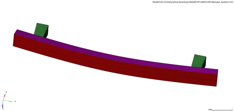
If the connections are not proper give proper connections
M 2 :- Solving different cases on crash tube
Case 1. Run the crash tube model as it is.
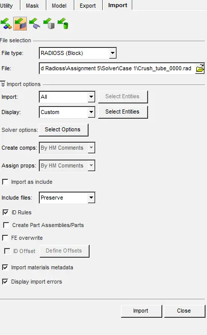
Import the model using import options "import solver deck" and rum the file without any changes
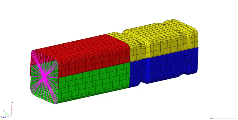
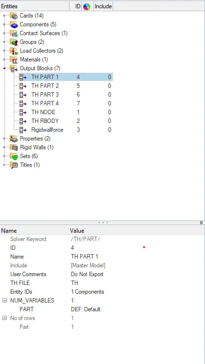
Create the TH_PART for the 4 parts from output blocks
Do the analysis

In the options box you can give the number of threds to perform the task if it not equired leave as it is.
Contact Forces :-
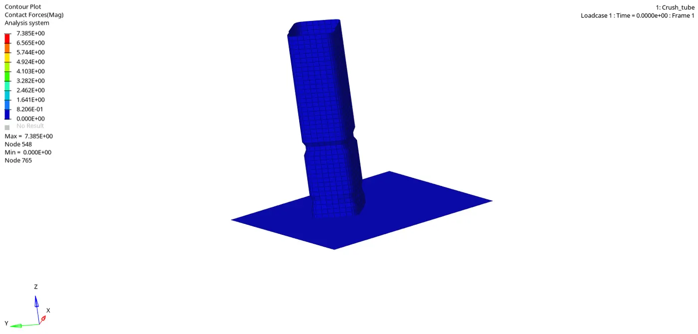
The Graphs are shown below
Internal Energy :-
Kinetic Energy :-
Rigid Wall forces :-
Contact energy :-
Do the same step we are followed till now for all other cases and make changes mention in the qustions
Case 2 :-
Change the Inacti=6 and run
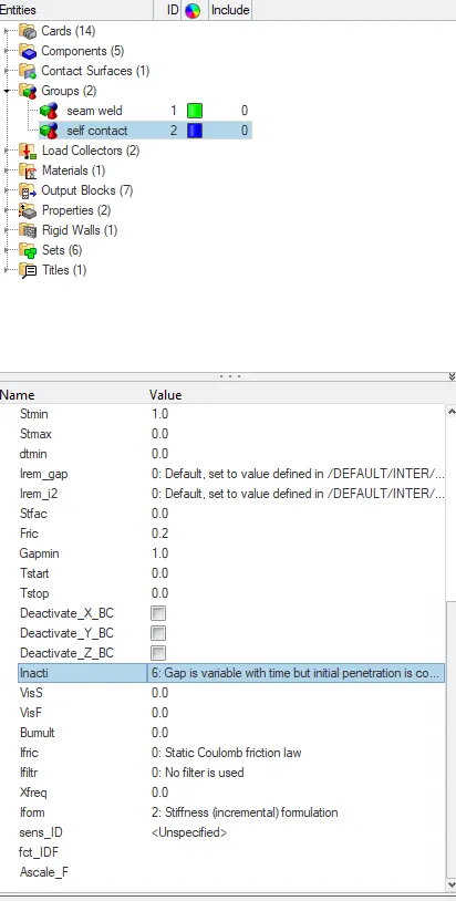
Do the Analysis and take the results
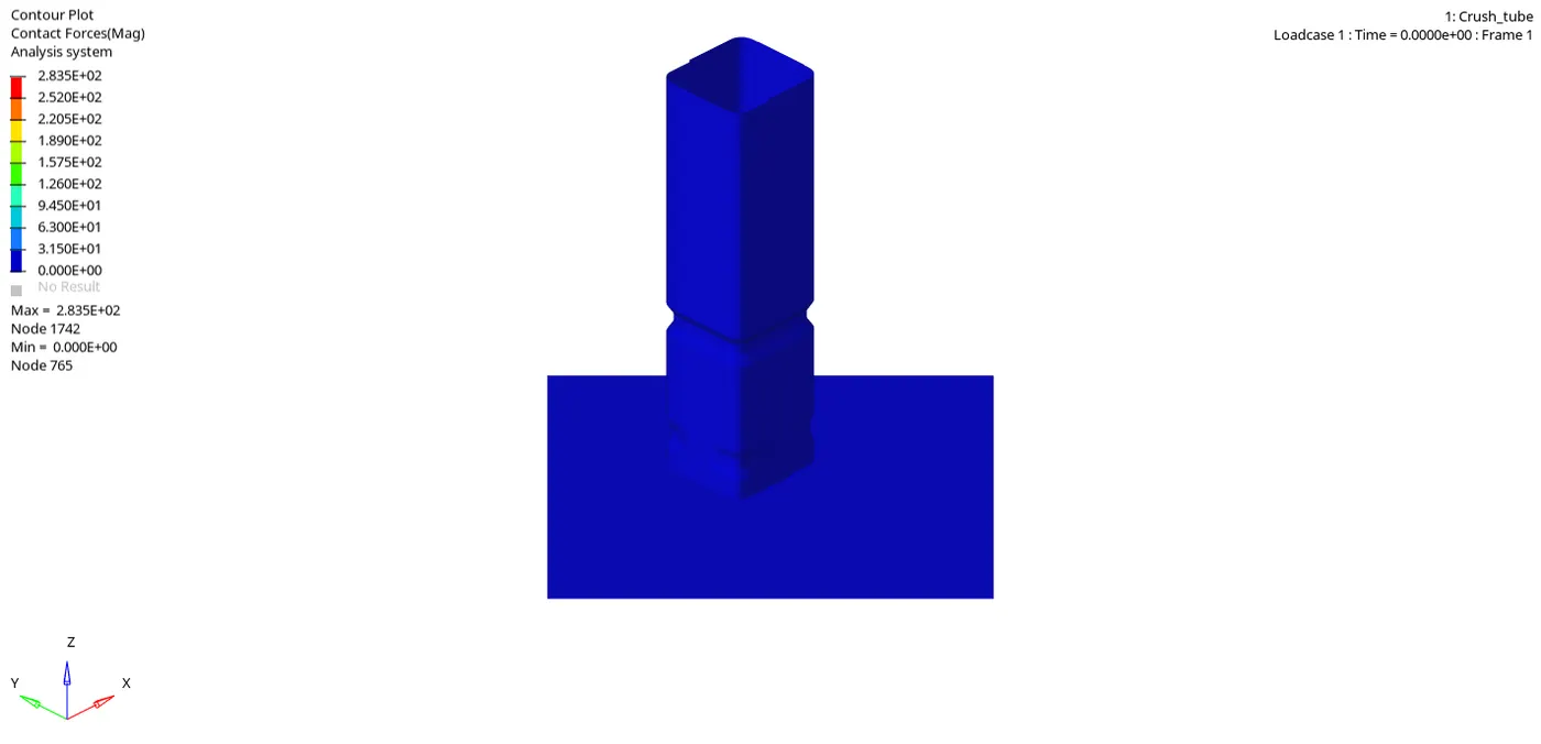
Contact Forces :-
Internal Energy :-
Kinetic Energy :-
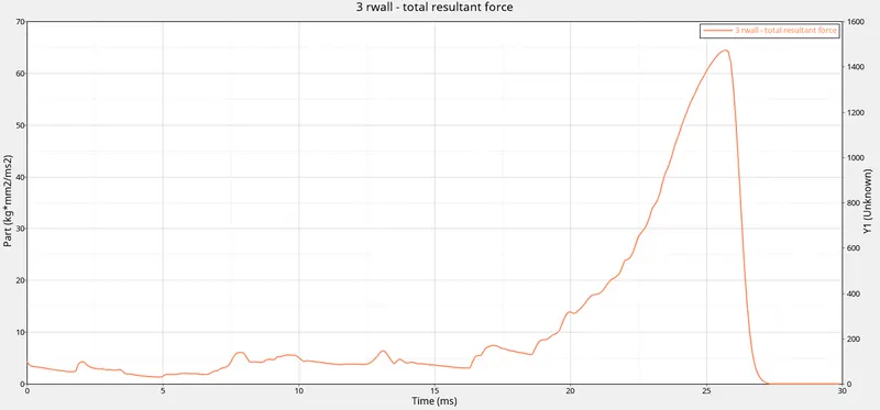
Rigid Wall forces :-
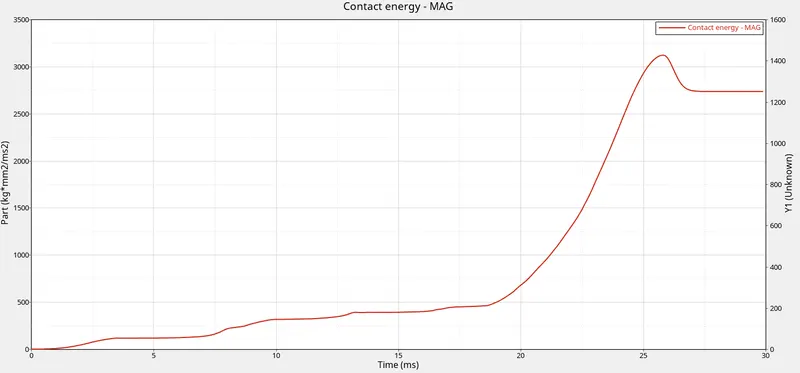
Contact energy :-
Case 3 :-
Do the analysis
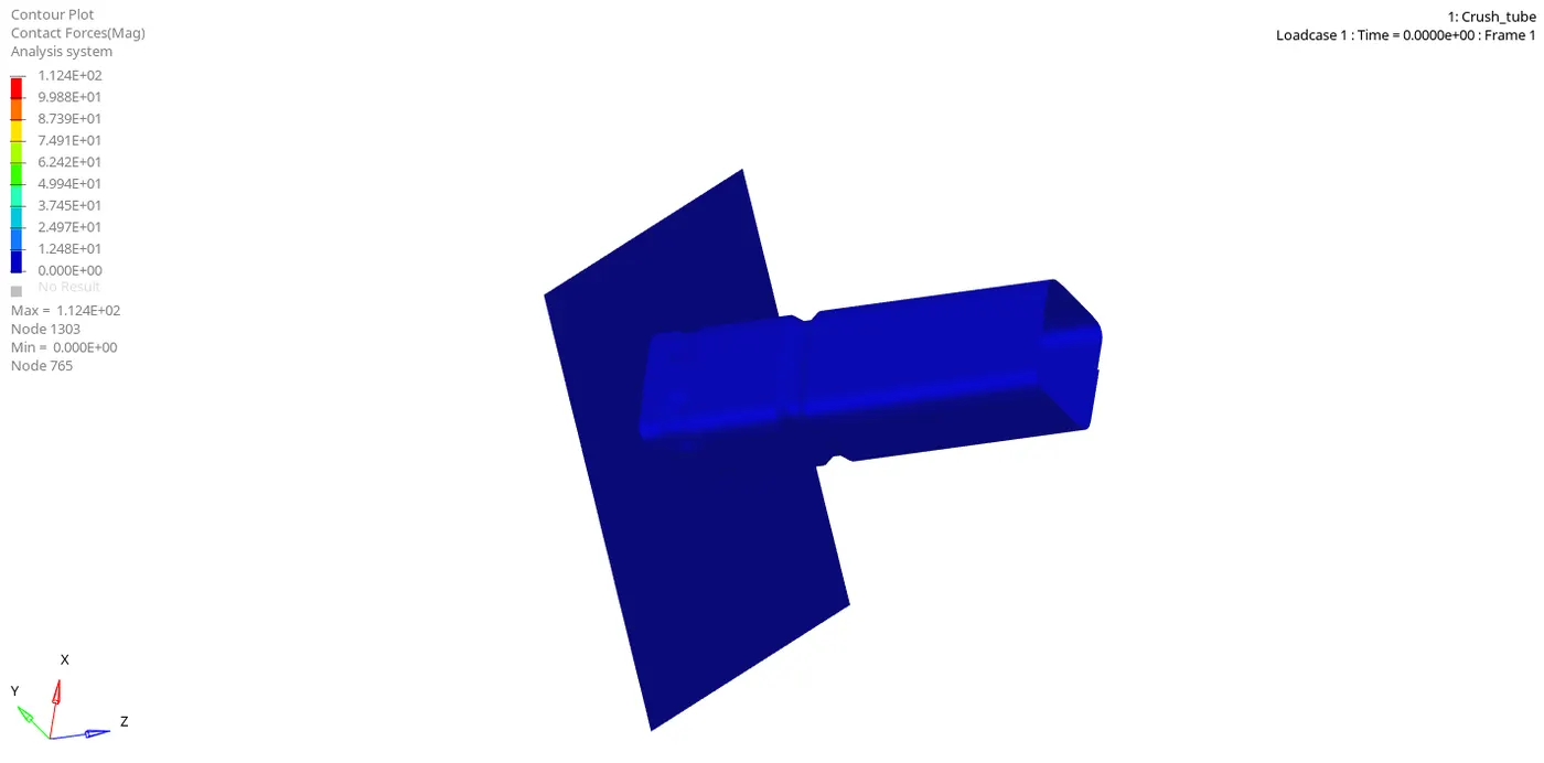
Contact Forces :-
Plotes
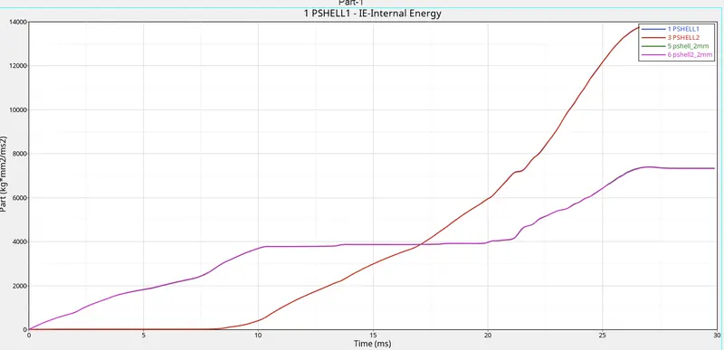
Internal Energy :-
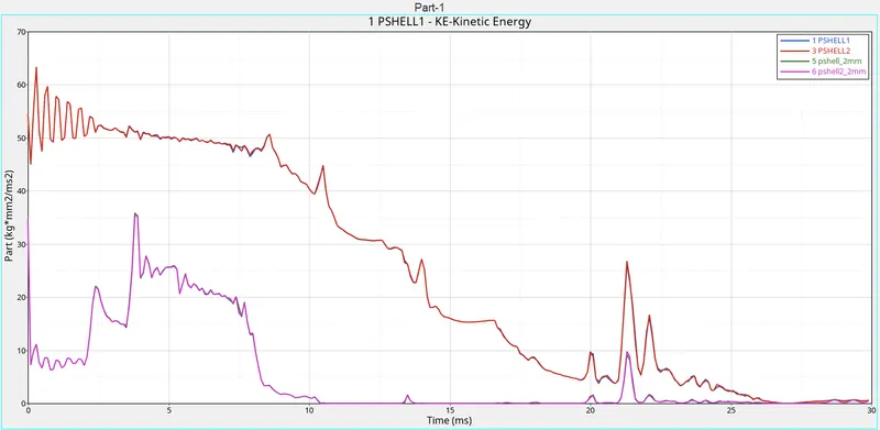
Kinetic Energy :-
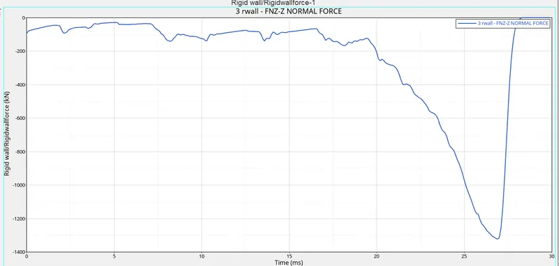
Rigid Wall forces :-
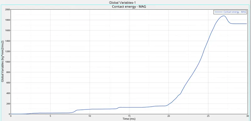
Contact energy :-
Case 4 :-
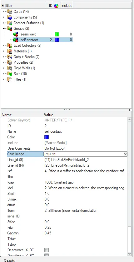
Create the type 11 contact and run.
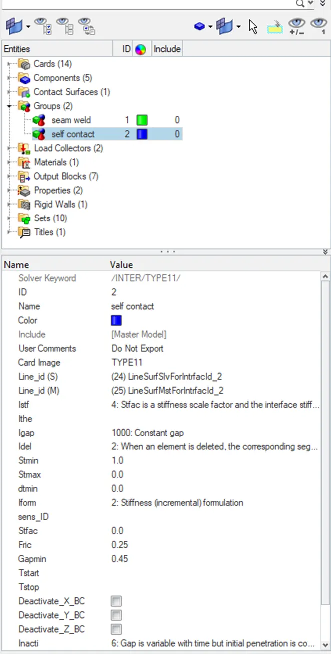
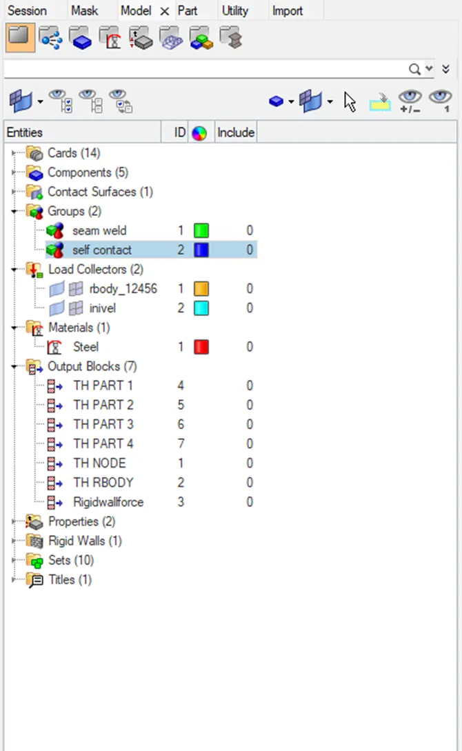
Open the groups section then go to self contact and set the contact as TYPE 11
Do the analysis
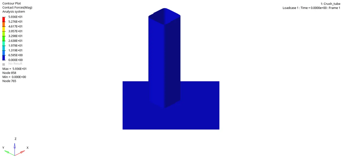
Contact Forces :-
Plotes
Internal Energy :-
Kinetic Energy :-
Rigid Wall forces :-
Contact energy :-
Case 5:-
Do the analysis
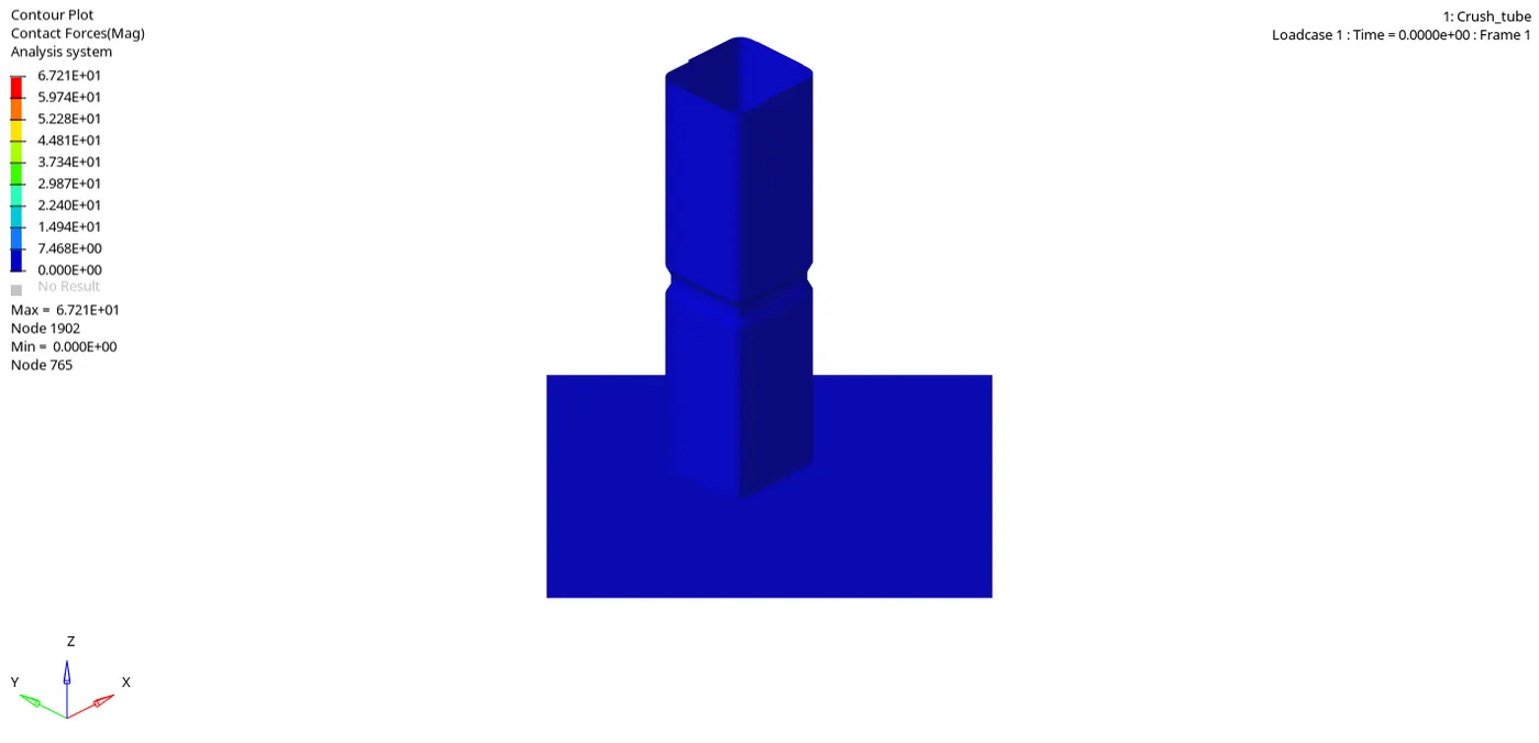
Contact Forces :-
Plotes
Internal Energy :-
Kinetic Energy :-
Rigid Wall forces :-
Contact energy :-
Case 6:-
Do the analysis
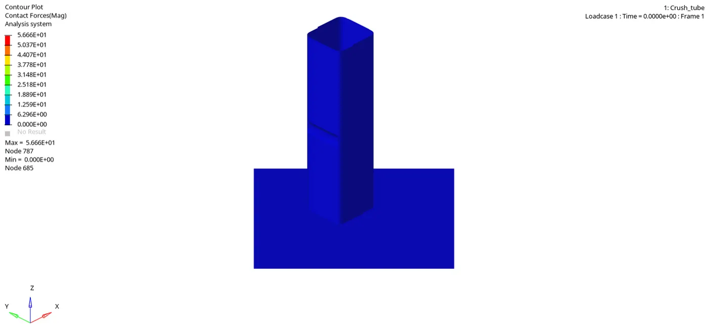
Contact Forces :-
Plotes
Internal Energy :-
Kinetic Energy :-
Rigid Wall forces :-
Contact energy :-
Observation :-
Case 1 :-
- For this simulation, the max von mises stress is created as 69.84 N/mm2 and the max contact force is created as 82 N. whereas the time history (TH) for all the components are created in order to study the deformation and energy variation in each component with respect to time.
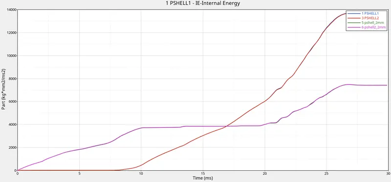
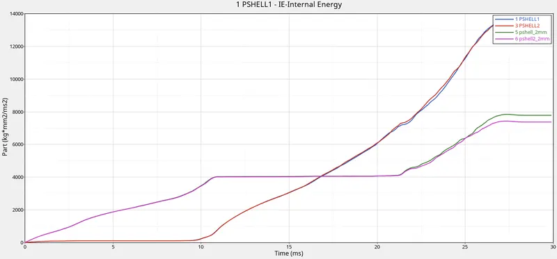
- The Internal energy for the p_shell_1 and p_shell_2 is increasing at the beginning because it is attached to the rigid wall and deform smoothly at the notch area where as the stiffness is less at this parts. The Internal energy for the p_shell_3 and p_shell_4 is zero for 10ms and linearly increasing to deform due to compression and the stiffness is high for this parts because of flat surface area.
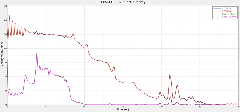
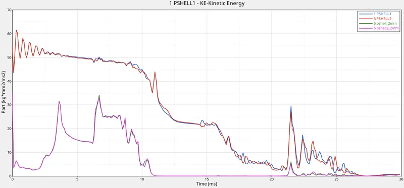
- There is no more deformation since the Kinetic energy for the p shell 1 and p shell 2 varies at first for 11 ms and then remains constant. It deforms fast due to the Notch area that is present over the components. Deformation occurs because the kinetic energy for the p shell 3 and p shell 4 is continually fluctuating over the course of 24 ms.
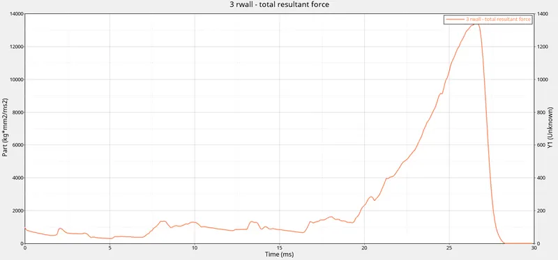
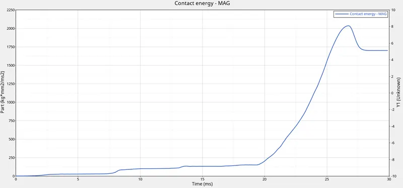
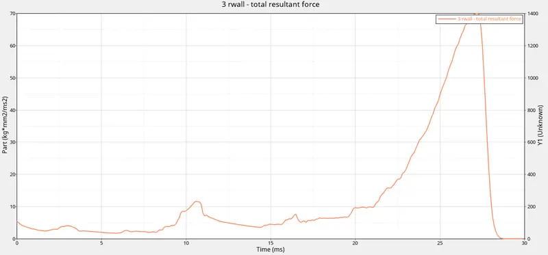
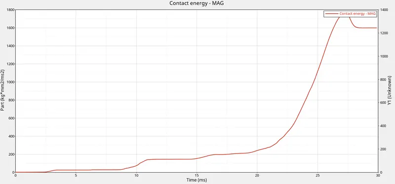
- Because a significant quantity of energy is created near the conclusion of deformation, the contact energy suddenly peaks out after initially fluctuating relatively little. The entire components are squeezed, producing a force of around 1400 Newton and energy of 2 kJ on the rigid wall.
Case 2 :-
- For this simulation, the max von mises stress is created as 60.68 N/mm2 and the max contact force is created as 74.03 N. whereas the time history (TH) for all the components are created in order to study the deformation and energy variation in each component with respect to time.
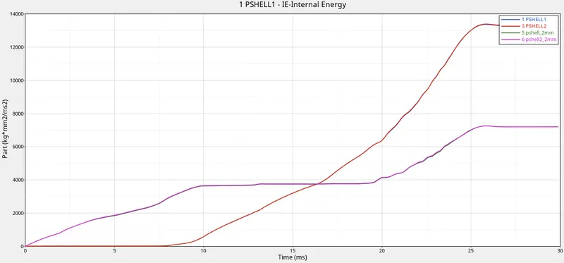
- The Internal energy for the p_shell_1 and p_shell_2 is increasing at the beginning because it is attached to the rigid wall and deform smoothly at the notch area where as the stiffness is less at this parts. The Internal energy for the p_shell_3 and p_shell_4 is zero for 8ms and linearly increasing to deform due to compression and the stiffness is high for this parts because of flat surface area.
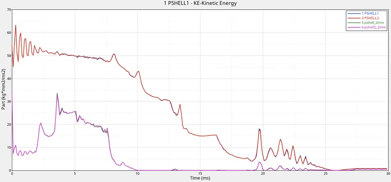
- There is no more deformation since the Kinetic energy for the p shell 1 and p shell 2 varies at first for 10 ms and then remains constant. It deforms fast due to the Notch area that is present over the components. Deformation occurs because the kinetic energy for the p shell 3 and p shell 4 is continually fluctuating over the course of 24 ms.
- Because a significant quantity of energy is created near the conclusion of deformation, the contact energy suddenly peaks out after initially fluctuating relatively little. The entire components are squeezed, producing a force of around 1500 Newton and energy of 3.2 kJ on the rigid wall.
Case 3 :-
- For this simulation, the max von mises stress is created as 75.04N/mm2 and the max contact force is created as 112.4 N. whereas the time history (TH) for all the components are created in order to study the deformation and energy variation in each component with respect to time.
- The Internal energy for the p_shell_1 and p_shell_2 is increasing at the beginning because it is attached to the rigid wall and deform smoothly at the notch area where as the stiffness is less at this parts. The Internal energy for the p_shell_3 and p_shell_4 is zero for 9ms and linearly increasing to deform due to compression and the stiffness is high for this parts because of flat surface area.
- There is no more deformation since the Kinetic energy for the p shell 1 and p shell 2 varies at first for 10 ms and then remains constant. It deforms fast due to the Notch area that is present over the components. Deformation occurs because the kinetic energy for the p shell 3 and p shell 4 is continually fluctuating over the course of 24 ms.
- Because a significant quantity of energy is created near the conclusion of deformation, the contact energy suddenly peaks out after initially fluctuating relatively little. The entire components are squeezed, producing a force of around 1300 Newton and energy of 1.9 kJ on the rigid wall.
Case 4 :-
- The crush tube doesn't have any notches, as may be seen here. Since there are no notches, there is no localised distortion during impact, and the deformation proceeds as anticipated.
- For this simulation, the max von mises stress is created as 60.68 N/mm2 and the max contact force is created as 59.36 N. whereas the time history (TH) for all the components are created in order to study the deformation and energy variation in each component with respect to time.
- The Internal energy for the p_shell_1 and p_shell_2 is increasing at the beginning because it is attached to the rigid wall and deform smoothly at the notch area where as the stiffness is less at this parts. The Internal energy for the p_shell_3 and p_shell_4 is zero for 8ms and linearly increasing to deform due to compression and the stiffness is high for this parts because of flat surface area.The absence of boundary conditions causes the total energy for each of the four components to change independently.
- There is no more deformation since the Kinetic energy for the p shell 1 and p shell 2 varies at first for 10 ms and then remains constant. It deforms fast due to the Notch area that is present over the components. Deformation occurs because the kinetic energy for the p shell 3 and p shell 4 is continually fluctuating over the course of 24 ms.
- Because a significant quantity of energy is created near the conclusion of deformation, the contact energy suddenly peaks out after initially fluctuating relatively little. The entire components are squeezed, producing a force of around 1500 Newton and energy of 3.2 kJ on the rigid wall.
Case 5 :-
- For this simulation, the max von mises stress is created as 81.56 N/mm2 and the max contact force is created as 67.2 N. whereas the time history (TH) for all the components are created in order to study the deformation and energy variation in each component with respect to time.
- The Internal energy for the p_shell_1 and p_shell_2 is increasing at the beginning because it is attached to the rigid wall and deform smoothly at the notch area where as the stiffness is less at this parts. The Internal energy for the p_shell_3 and p_shell_4 is zero for 10ms and linearly increasing to deform due to compression and the stiffness is high for this parts because of flat surface area.The absence of boundary conditions causes the total energy for each of the four components to change independently.
- There is no more deformation since the Kinetic energy for the p shell 1 and p shell 2 varies at first for 11 ms and then remains constant. It deforms fast due to the Notch area that is present over the components. Deformation occurs because the kinetic energy for the p shell 3 and p shell 4 is continually fluctuating over the course of 25 ms.
- Because a significant quantity of energy is created near the conclusion of deformation, the contact energy suddenly peaks out after initially fluctuating relatively little. The entire components are squeezed, producing a force of around 1450 Newton and energy of 1.8 kJ on the rigid wall.
Case 6 :-
- For this simulation, the max von mises stress is created as 73.91 N/mm2 and the max contact force is created as 56.66 N. whereas the time history (TH) for all the components are created in order to study the deformation and energy variation in each component with respect to time.
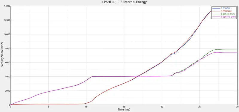
- The Internal energy for the p_shell_1 and p_shell_2 is increasing at the beginning because it is attached to the rigid wall and deform smoothly at the notch area where as the stiffness is less at this parts. The Internal energy for the p_shell_3 and p_shell_4 is zero for 10ms and linearly increasing to deform due to compression and the stiffness is high for this parts because of flat surface area.The absence of boundary conditions causes the total energy for each of the four components to change independently.
- There is no more deformation since the Kinetic energy for the p shell 1 and p shell 2 varies at first for 11 ms and then remains constant. It deforms fast due to the Notch area that is present over the components. Deformation occurs because the kinetic energy for the p shell 3 and p shell 4 is continually fluctuating over the course of 25 ms.
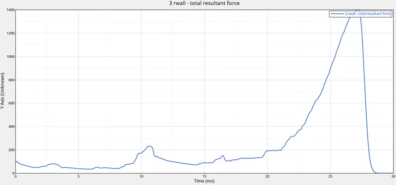
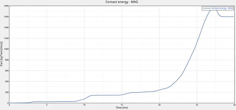
- Because a significant quantity of energy is created near the conclusion of deformation, the contact energy suddenly peaks out after initially fluctuating relatively little. The entire components are squeezed, producing a force of around 1400 Newton and energy of 1.8 kJ on the rigid wall.
Results :-
- Comparison of energy errors, Maximum Contact force, Maximum Rigid wall force,mass errors, and Maximum Contact energy are given in below table.
|
Case no. |
Particulars |
Energy Error (%) |
Mass Error (%) |
Max. Contact force (N) |
Max. Rigid wall force (N) |
Max. Contact energy (KJ) |
Reason |
|
Case1 |
Running model as it is |
-3.8 |
0 |
82 |
1400 |
2 |
Node to Surface Contact Type 7 |
|
Case2 |
Change Inacti = 6 |
-6.2 |
0 |
74.03 |
1500 |
3.2 |
No Initial Penetrations found |
|
Case3 |
Type 11 Interface |
-3.9 |
0 |
112.4 |
1300 |
1.9 |
Type 11 Edge to Edge Contact |
|
Case4 |
Removing notches and Boundary conditions |
-2.5 |
0 |
59.36 |
1500 |
3.2 |
No boundary condition and flat surface |
|
Case5 |
Creating new notch to middle |
-3.6 |
0 |
67.2 |
1450 |
1.8 |
ability to absorb increased due to middle notch |
|
Case6 |
Creating notch only on opposite side |
-3.2 |
0 |
56.66 |
1400 |
1.8 |
due to Opposing notches created |
- The notch is what caused the internal energy to alter. The internal energy drops when the notch is removed, which also lowers the energy error.
- High strains cause the notch regions to deform first. Low amounts of tension are present in the plane surface where the notches were eliminated. As a result, we can say that eliminating the notch helps to lower the stress on the body.
Conclusion :-
- The 6mm element size has been meshed and welded (seam) on the bumper model, making it suitable for additional solving and post-processing.
- All the 6 cases of crash tube have been simulated and results are compared using various energies plot.