Assignment 5-RADIOSS Interfaces & Study of Effect of Notches Challenge
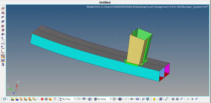
Create the mesh for bumper assembly, mesh size should be 6mm.
Objective
To mesh the given bumper model with a mesh size of 6 mm.
To run the crash tube simulation with given 6 cases and plot the graph for energies.
Procedure
Import the .hm file. Go to File > Import > model. Click on the Select File icon. Select the .hm file and click on Import.
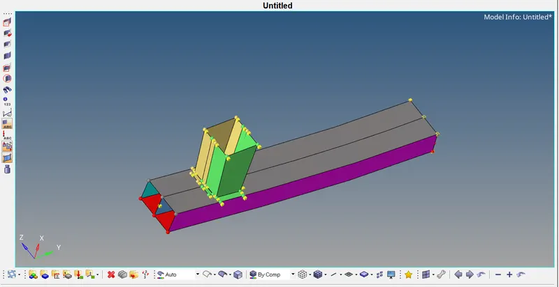
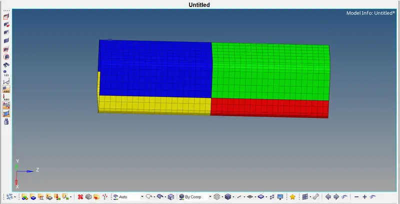
Switch to By Topo geometry color mode. Few free edges are found. These are easily fixed by using the surface edit tool and edge edit tool available under the Geom page.
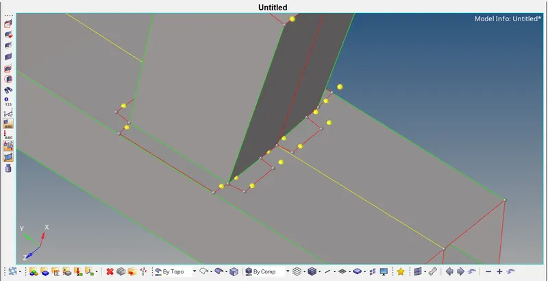
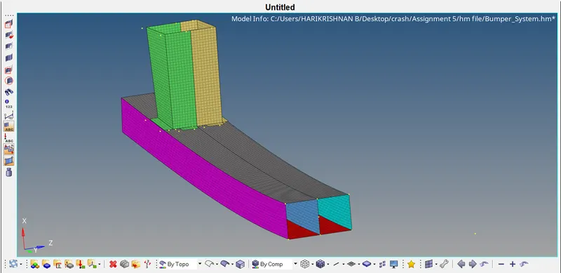
Go to Preferences > Criteria File Settings > Target element size. Enter Target element size = 6. Now press F12 to go to the auto mesh panel. Enter element size =6 and mesh type to 6. Perform the meshing manually surface by surface.
Now connect the crash boxes with the bumper using a spot weld. Go to 1D > connectors > spot > spot. In the location selector, select the nodes of the crash box. In connect what selector, select the
components to be connected, i.e crash box and bumper rear. enter no. of layers = 2 and search tolerance as 2.5. Select type as weld with diameter = 2 and click on create. The connectors will be created as seen below.
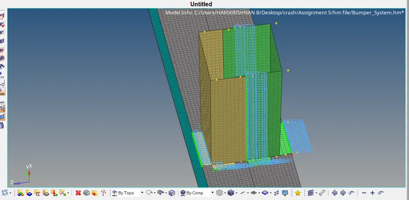
Thus, meshing is done on the bumper and the crash boxes are connected to the bumper using 1D connectors.
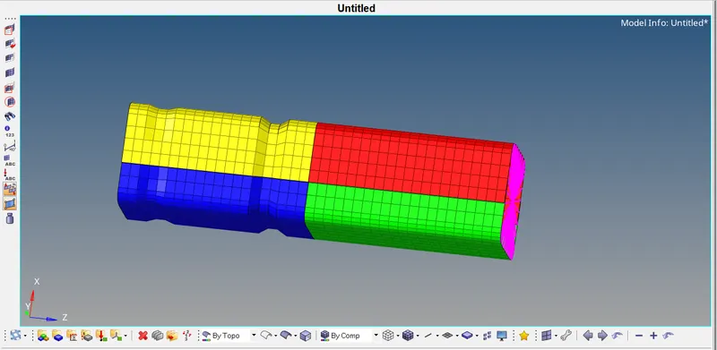
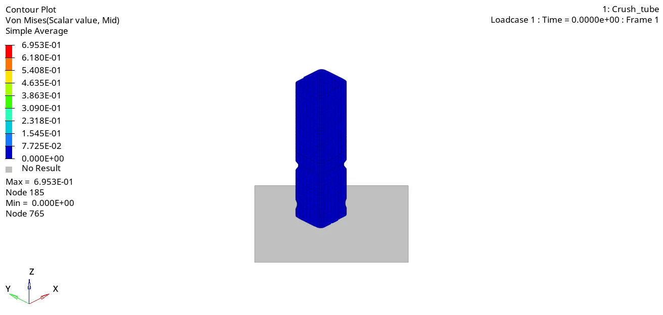
Case 1: Run the crash tube model as it is.
We have to run the simulation as it is with no changes. Open Hypermesh with the user profile as Radioss. To import the 0000.rad file, click on File > Import > Solver deck, and import the file.
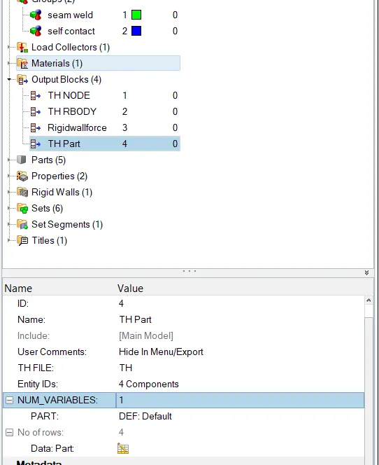

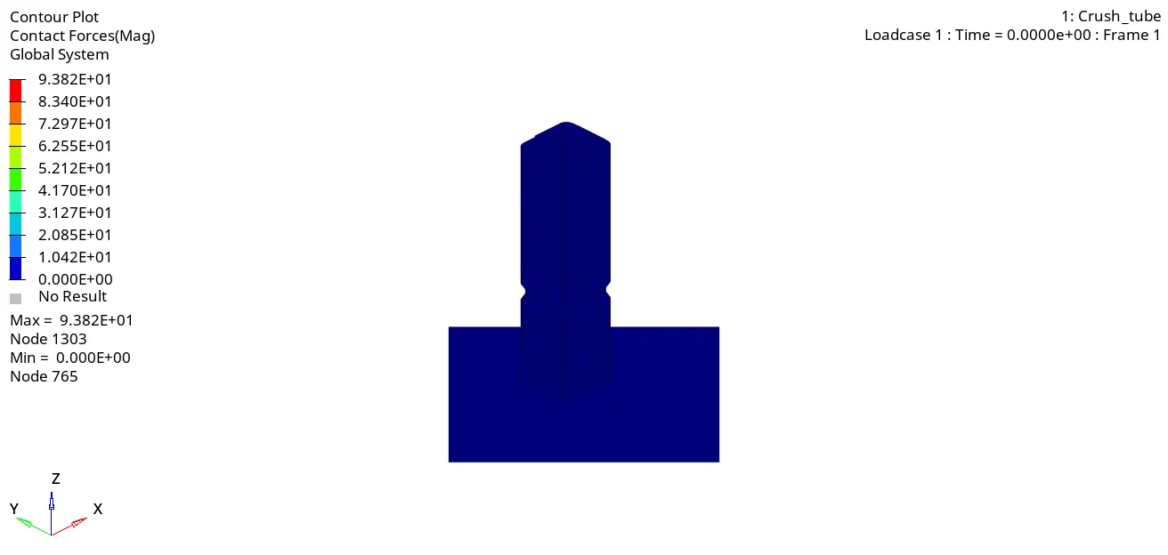
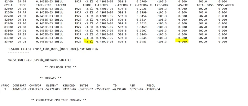
Open hypergraph 2d for observing the energy plot data from the TA01 file.
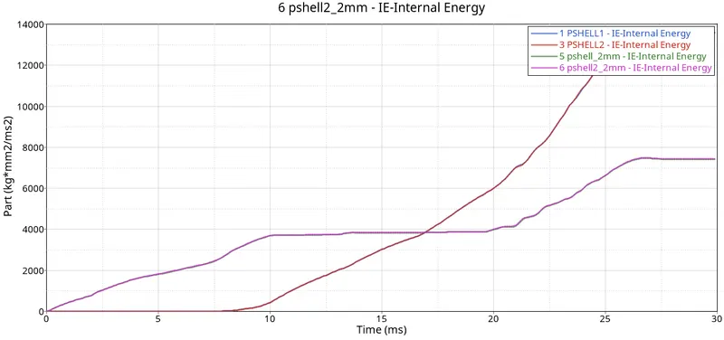
The Internal energy for the p_shell_2 components is increasing at the beginning because it is attached to the rigid wall and deforms smoothly at the notch area whereas the stiffness is less at these parts. The Internal energy for the p_shell_3 components is zero for 10ms and linearly increases to deform (compression takes place) and the stiffness is high for these parts because of the flat surface area.
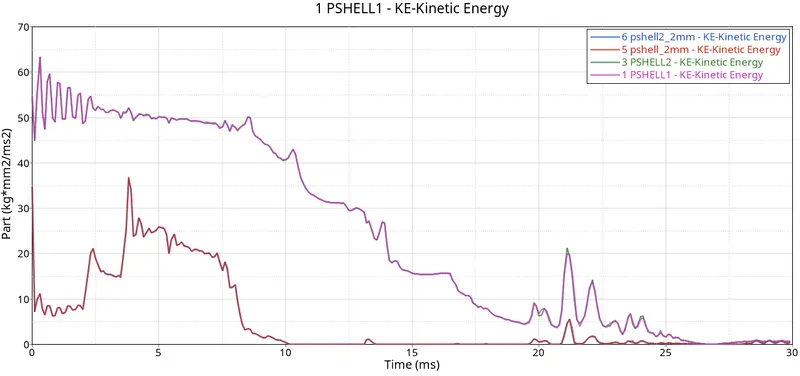
The Kinetic energy for the p_shell_2 components is varying at the beginning for 10ms and is maintained as constant which means no more deformation occurs. Because of Notch area presents over the components it deforms very quickly. The Kinetic energy for the p_shell_3 components continuously varies over the time of 25ms means deformation takes place (compression) at a velocity of 13.3 m/s.
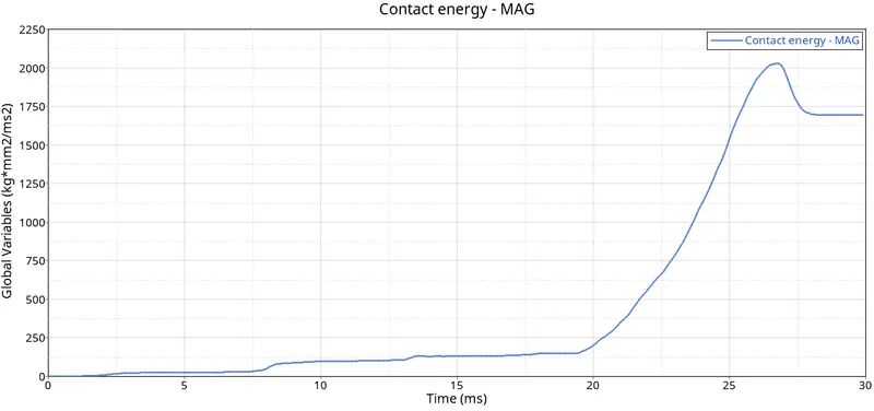
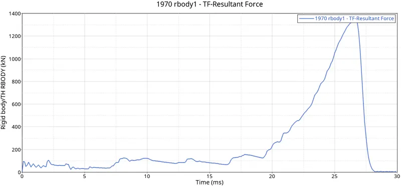
The contact energy is varying at a very small amount at the beginning and there is a sudden peak formed because there is a large amount of energy developed at the end of the deformation. The overall elements became compressed which will develop a large force on the rigid wall around 1400 Newton and energy created as 2 kJ.
The Internal energy for the p_shell_2.0 components is increasing at the beginning because it is attached to the rigid wall and deforms smoothly from the notch area whereas the stiffness is less at this part. The Internal energy for the 0 components is zero for 10ms and linearly increases to deform (compression takes place) at a velocity of 13.3 m/s and the stiffness is high for this part because of the flat surface area.
The Kinetic energy for the p_shell_2.0 components is varying at the beginning for 10ms and is maintained constant which means no more deformation occurs. Because of Notch area presents over the components it deforms very quickly. The Kinetic energy for the p_shell_3.0 components continuously varies over the time of 25ms means deformation takes place (compression) at a velocity of 13.3 m/s.
The contact energy is varying at a very small amount at the beginning and there is a sudden peak formed because there is a large amount of energy developed at the end of the deformation. The overall elements are becoming overlapped or compressed which will develop large force on the rigid wall around 1500 Newton and energy created as 2.6 kJ.
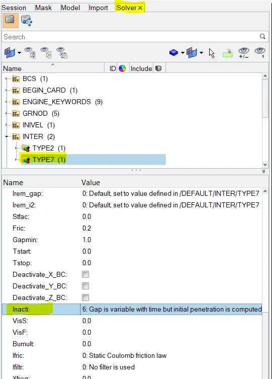
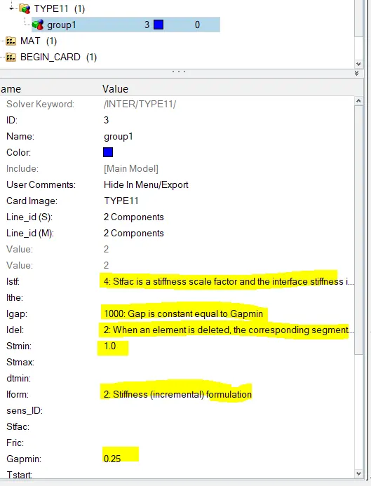
In this case, the model is imported and run the simulation with recommended properties whereas we have to change the Card image as Type 11 contact as per the problem statement.
Type 11 takes into account the connections made by the edges of the slave segment to the edges of to the master segment and hence improves the accuracy of the reactive forces calculations.
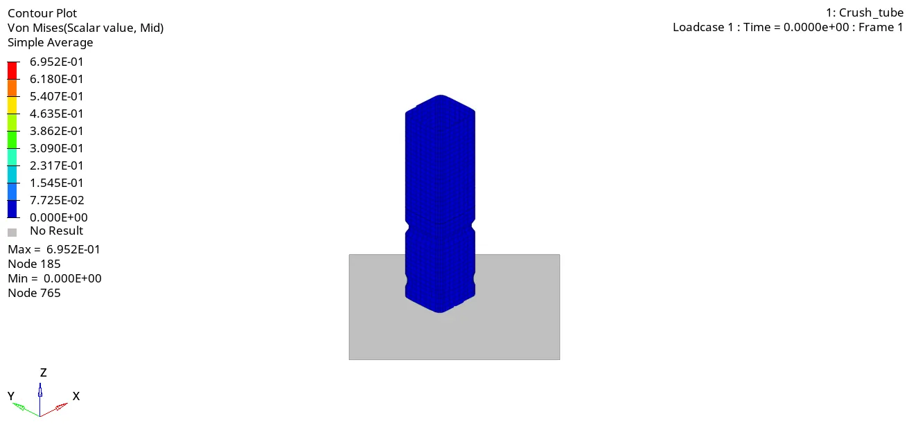
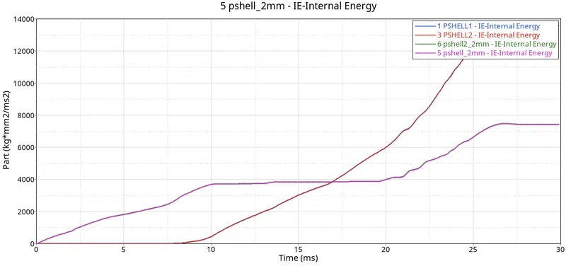
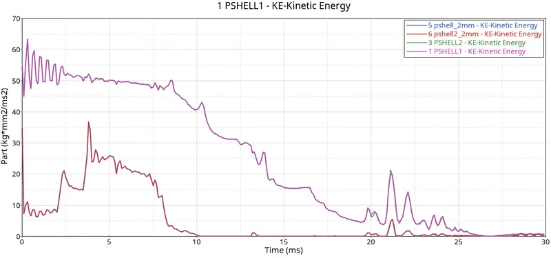
The Internal energy for the 2mm shell components is increasing at the beginning because it is attached to the rigid wall and deforms smoothly from the notch area whereas the stiffness is less at this part. The Internal energy for the 3mm shell components is zero for 10ms and linearly increases to deform (compression takes place) at a velocity of 13.3 m/s and the stiffness is high for this part because of the flat surface area. The end of this component defines the rigidity with a translational (z-direction) degree of freedom.
The Kinetic energy for the 2mm shell components is varying at the beginning for 10ms and is maintained as constant which means no more deformation occurs. Because of Notch area presents over the components it deforms very quickly. The Kinetic energy for the 3mm shell components continuously varies over the time 25ms means deformation takes place (compression) at a velocity of 13.3 m/s.
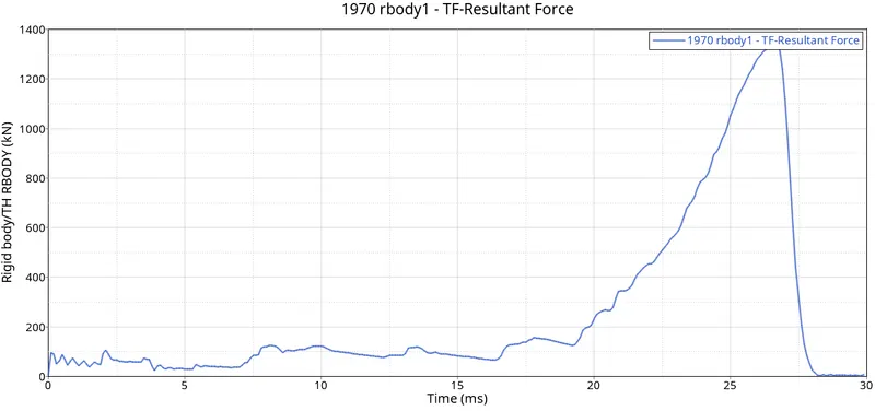
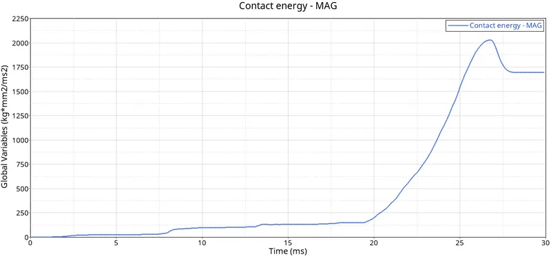
The contact energy is varying at a very small amount at the beginning and there is a sudden peak formed because there is a large amount of energy developed at the end of the deformation. The overall elements are becoming overlapped or compressed which will develop a large force on the rigid wall around 1300 Newton and energy created as 1.9 kJ.
To delete the Notch, go to the Tools panel and select Delete option > Select the Elements to delete > Click on delete Entity.
The Notch elements are deleted.
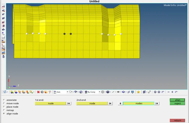
To create a plane surface, go to the 2D panel, Select Ruled option > Select the first Node list > Select the Second Node List > Click Create. >> The mesh is created Give the element length as 6 > Click Recalculate > Click mesh.
The mesh is created properly.
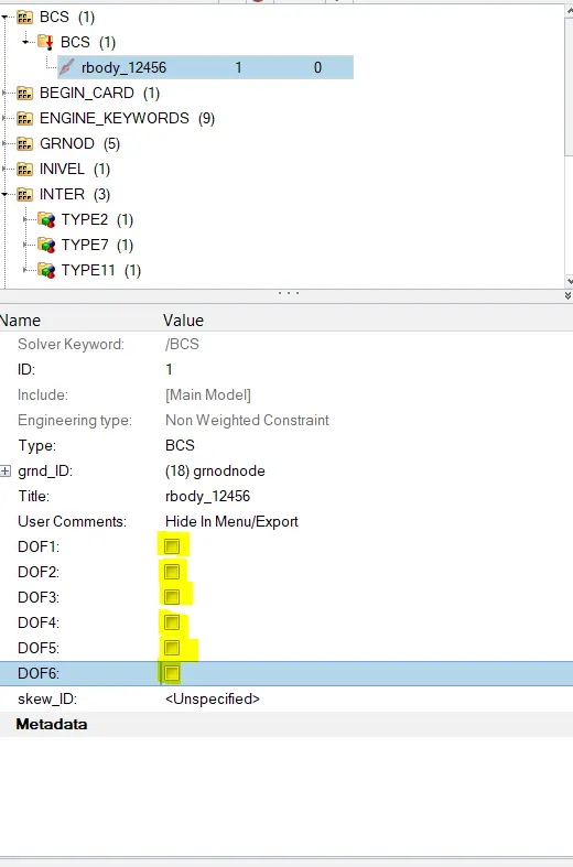
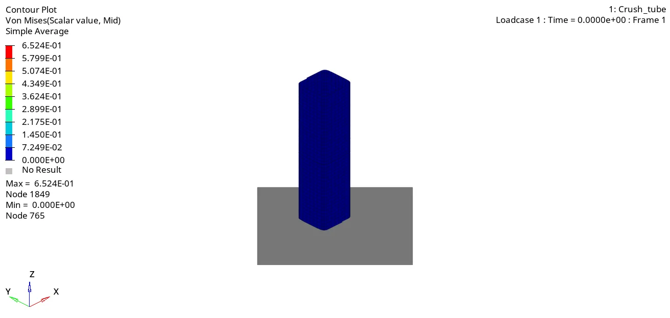
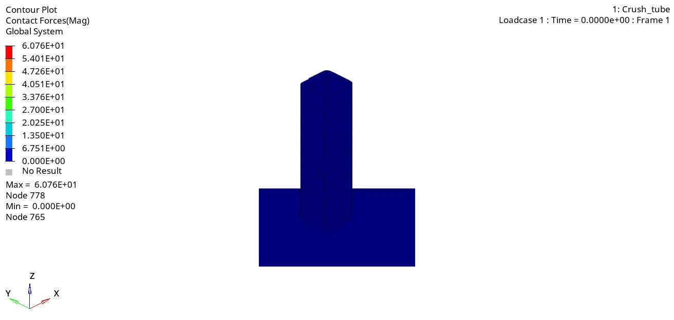
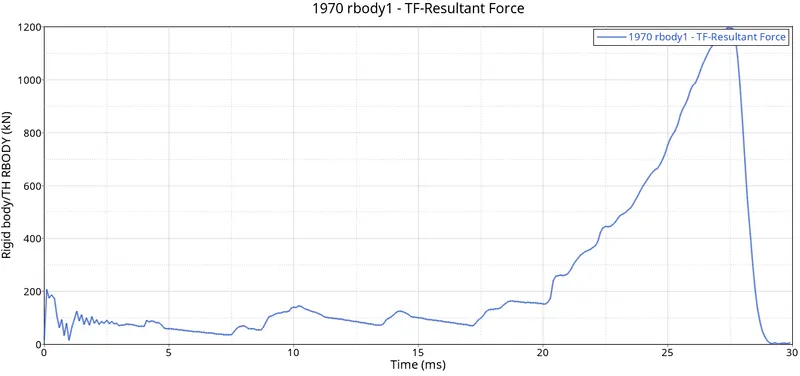
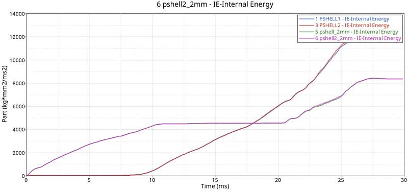
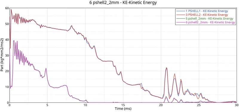
The Internal energy for the p_shell_2.0 components is increasing at the beginning because it is attached to the rigid wall and deforms smoothly there is no notch area whereas the stiffness is constant throughout the model. The Internal energy for the p_shell_3.0 components is zero for 10ms and linearly increases to deform (compression takes place) at a velocity of 13.3 m/s. The end of these components defines the rigidity with a translational (z-direction) degree of freedom. The Total energy for all 4 components are varying individually with the absence of boundary conditions.
The Kinetic energy for the p_shell_2.0 components is varying at the beginning for 10ms and is maintained as constant which means no more deformation occurs. Because of Notch area presents over the components it deforms very quickly. The Kinetic energy for the p_shell_3.0 components continuously varies over the time of 25ms means deformation takes place (compression) at a velocity of 13.3 m/s.
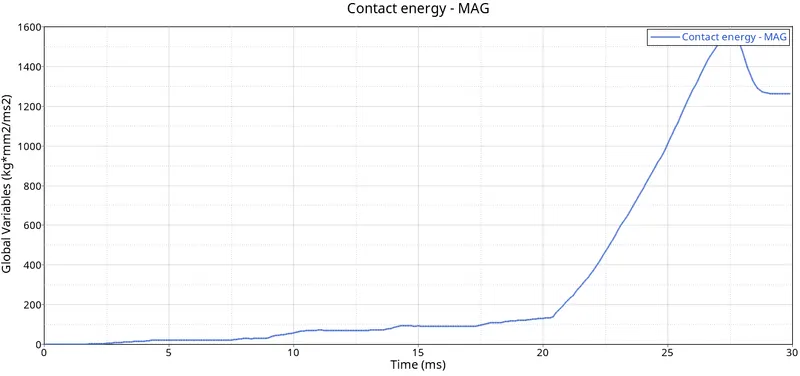
The contact energy is varying at a very small amount at the beginning and there is a sudden peak formed because there is a large amount of energy developed at the end of the deformation. The overall elements are became overlapped or compressed which will develop a large force on the rigid wall around 1200 Newton and the energy created is 1.3 kJ.
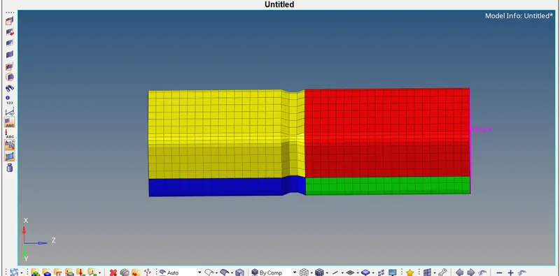
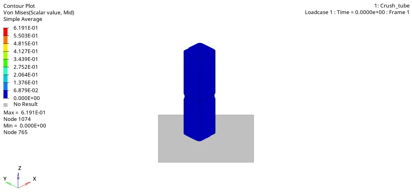
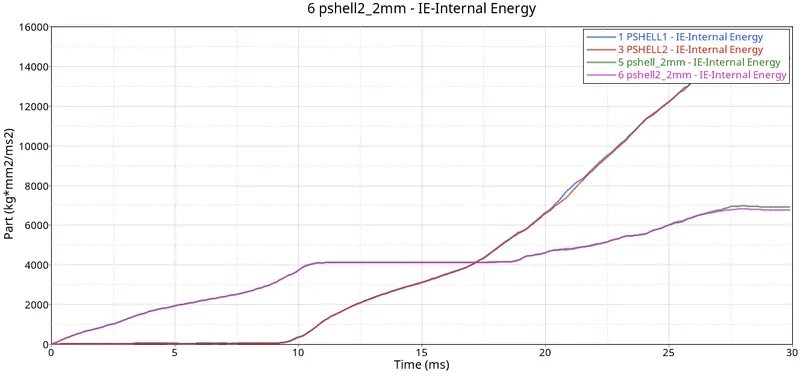
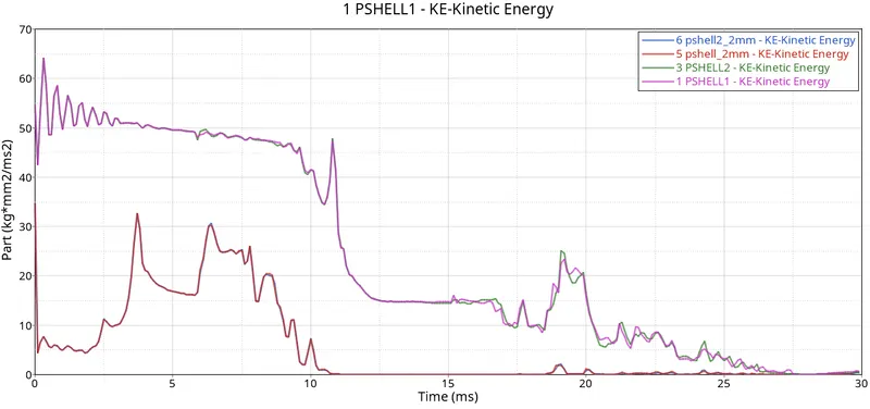
The Internal energy for the p_shell_2.0 components is increasing at the beginning because it is attached to the rigid wall and deforms smoothly there is no notch area whereas the stiffness is constant throughout the model. The Internal energy for the p_shell_3.0 components is zero for 10ms and linearly increases to deform (compression takes place) at a velocity of 13.3 m/s. The end of this component defines the rigidity with a translational (z-direction) degree of freedom. The Total energy for all 4 components are varying individually with the absence of boundary conditions.
The Kinetic energy for the p_shell_2.0 components is varying at the beginning for 10ms and is maintained as constant which means no more deformation occurs. Because of Notch area presents over the components it deforms very quickly. The Kinetic energy for the p_shell_3.0 components continuously varies over the time of 25ms means deformation takes place (compression) at a velocity of 13.3 m/s.
The contact energy is varying at a very small amount at the beginning and there is a sudden peak formed because there is a large amount of energy developed at the end of the deformation. The overall elements are becoming overlapped or compressed which will develop a large force on the rigid wall around 1300 Newton and the energy created is 1.7 kJ.
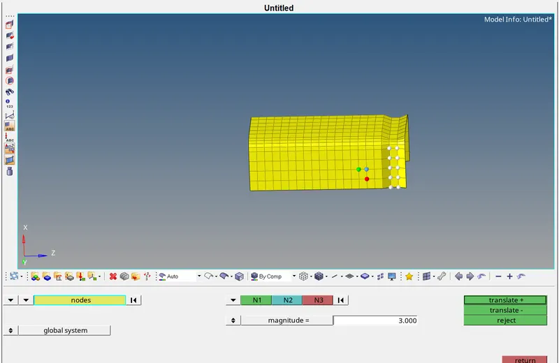
Go to the Tools panel, Select the Translate option > Select the Nodes to translate > Select the Orientation of the elements (i.e., in which direction the elements should be moved) > Give the Magnitude as 5 (Distance from node to node). The Notch is created.
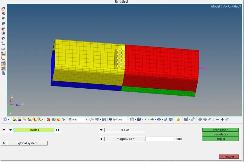
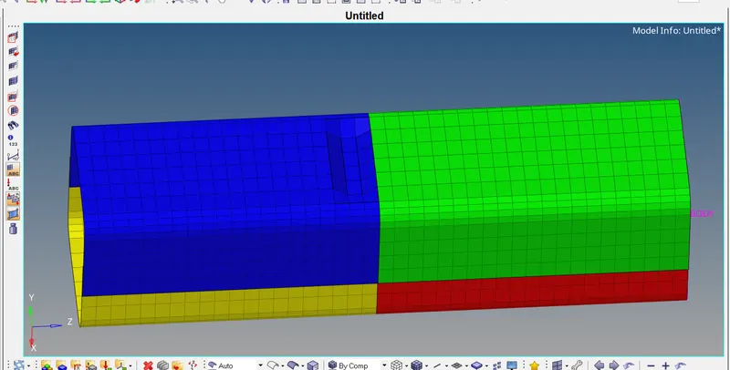
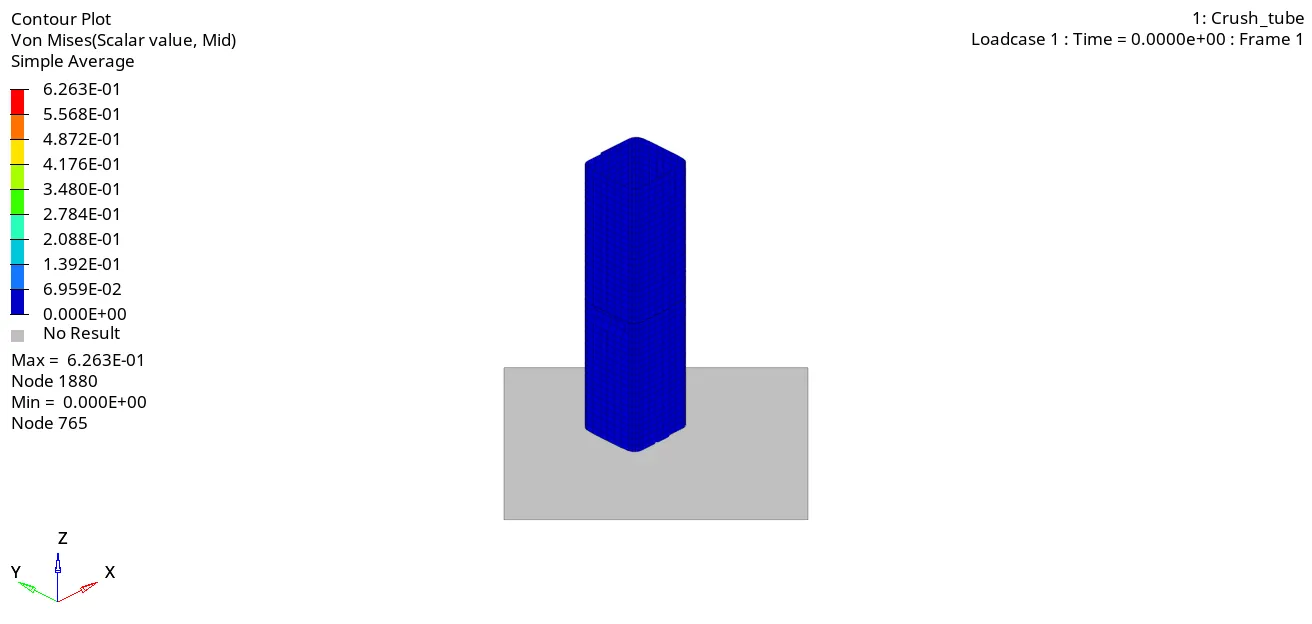
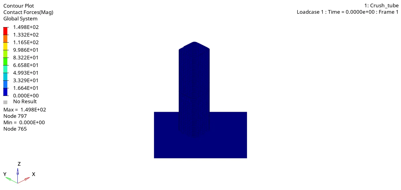
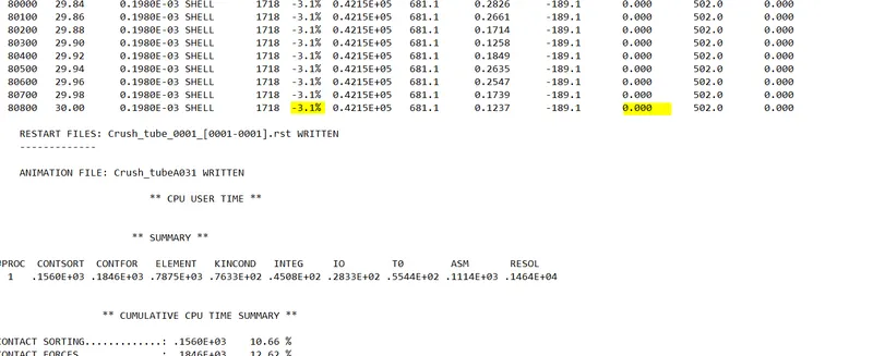
Open hypergraph 2d for observing the energy plot data from TA01 file.
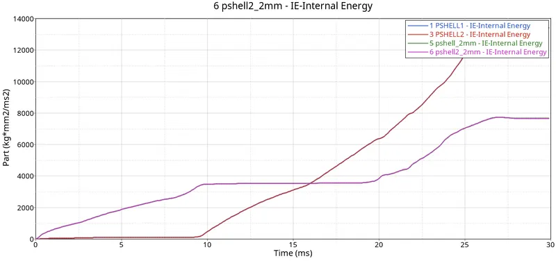
The Internal energy for the 2mm shell components is increasing at the beginning because it is attached to the rigid wall and deforms smoothly there is a notch on the middle opposite 2 surfaces whereas the stiffness is less. The Internal energy for the 3mm shell components is zero for 10ms and linearly increases to deform (compression takes place) at a velocity of 13.3 m/s. The end of this component defines the rigidity with a translational (z-direction) degree of freedom. The Total energy for all the 4 components is varying individually with an absence of boundary conditions.
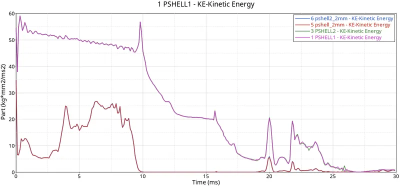
The Kinetic energy for the 2mm shell components is varying at the beginning for 10ms and is maintained as constant which means no more deformation occurs. Because of Notch area presents over the components it deforms very quickly. The Kinetic energy for the 3mm shell components continuously varies over the time 25ms means deformation takes place (compression) at a velocity of 13.3 m/s.
When objects collide, contact forces transfer energy so as to change the objects' motions. When two objects interact, each one exerts a force on the other, and these forces can transfer energy between them. Fields contain energy that depends on the arrangement of the objects in the field.
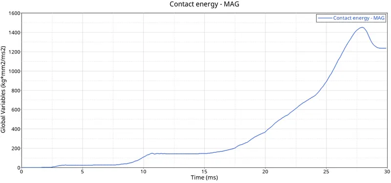
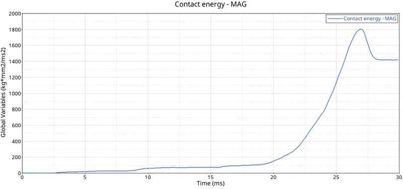
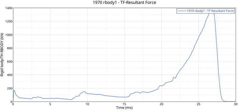
The contact energy is varying at a very small amount at the beginning and there is a sudden peak formed because there is a large amount of energy developed at the end of the deformation. The overall elements are becoming overlapped or compressed which will develop a large force on the rigid wall around 1100 Newton and energy created as 1.5 kJ.
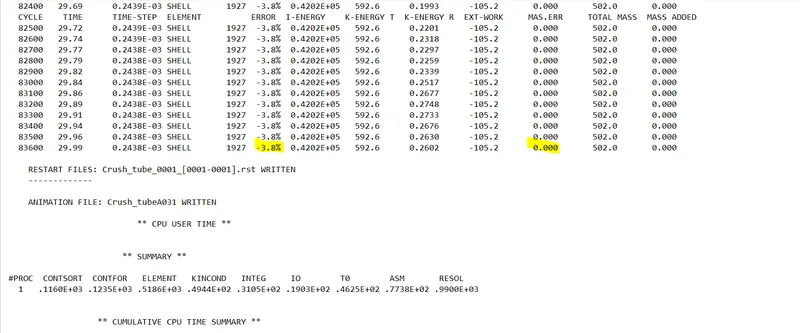
| Case no. | Particulars | Energy Error (%) |
Mass Error (%) | Max. Contact force (N) | Max. Rigid wall force (N) | Max. Contact Energy (KJ) | Reason |
|
Case1 |
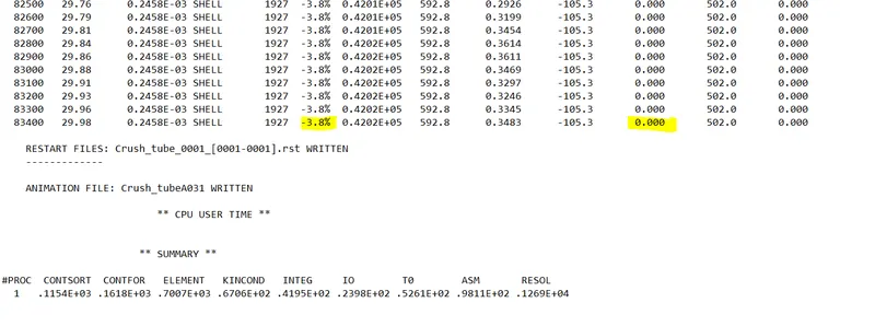
Running model as it is | -3.8 | 0 | 93.82 | 1400 | 2 | Node to Surface Contact Type 7 |
|
Case2 |
Change Inacti = 6 | -3.8 | 0 | 93.82 | 1400 | 2 | No Initial Penetrations found |
|
Case3 |
Type 11 Interface |
-3.8 |
0 | 93.97 | 1350 |
2 |
Type 11 Edge to Edge Contact |
|
Case4 |
Removing notches and BC’s |
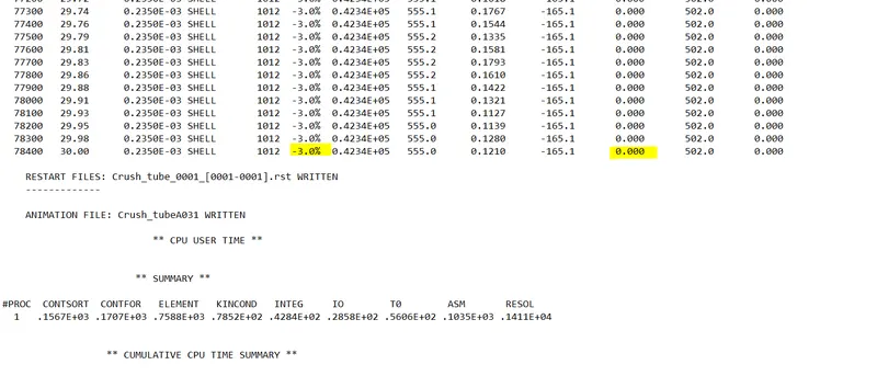
-3.0 |
0 |
60.76 |
1200 |
1.6 |
No boundary condition; flat surface |
|
Case5 |
Creating new notch to middle |
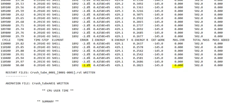
-2.8 |
0 |
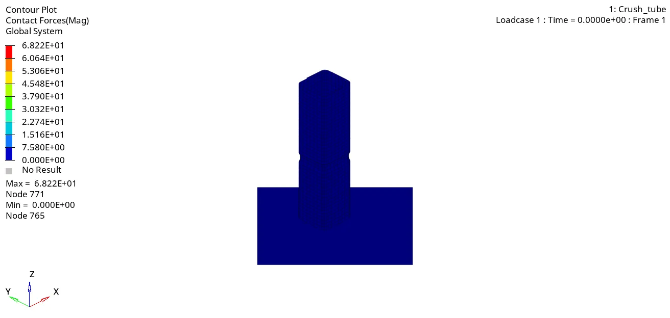
68.22 |
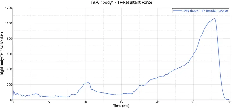
1050 |
1.4 |
ability to absorb increased due to middle notch |
|
Case6 |
Creating notch only on the opposite side |
-3.1 |
0 | 149.8 | 1400 | 1.8 | due to Opposing notches |
The change in the internal energy is due to the notch. With the removal of the notch, the internal energy decreases and hence reduces the energy error as well. The notch areas have high stresses and deform first. On the plane surface where the notches are removed the stress levels are low. Hence, we can state that removing the notch helps to reduce the stress acting on the body. 3mm shell requires higher internal energy; it means the ability to absorb force is higher in the shell with 3mm thickness compared to a shell with 2mm thickness. More thickness of the shell has more internal energy for the component.
Conclusion
The Bumper model has been meshed and welded (seam) with an element size of 6mm and is ready for further solving and post-processing.
All 6 cases of the crash tube have been simulated and results are compared using various energies plot.