Assignment 5-RADIOSS Interfaces & Study of Effect of Notches Challenge
Objective:
- To create the mesh for bumper assembly, with mesh size 6mm.
- Run the crash tube model as it is.
- Change the Inacti=6 and run.
- Create the type 11 contact and run.
- Remove both notches and remove boundary condition on rigid body node then run.
- Create a new notch in the middle ,select the whole section and run.
- Create a new notch with nodes only from opposing 2 faces and run.
Also,
- Plot RWALL forces ,contact forces,internal energy and Create TH/PART for all parts and compare results for all cases.
- Comment on why there is a change in the internal energies.
- How does the notch affect the results?
- Plot energies and notice any difference.
Solution:
Part 1 : Meshing.
- To Perform meshing some geometry cleanup is needed.
- First we attach the flanges from Crash Upper Box and Crash lower Box to its respective components. To do this go to quick edeit>project the points of flange ends on crash box> replace the points with ones on the crashbox.
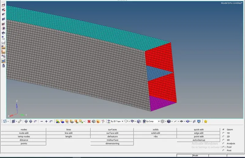
- Create 2D mesh on crash box
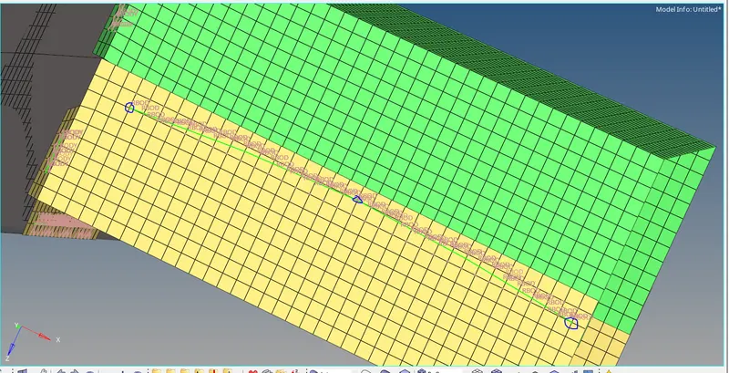
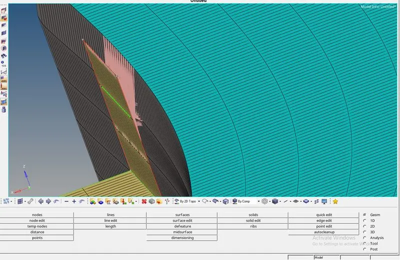
- Go to 1D>connectors>spot. select three spot weld points and then select the two components to join>give tolerance of 1 mm>hit create.
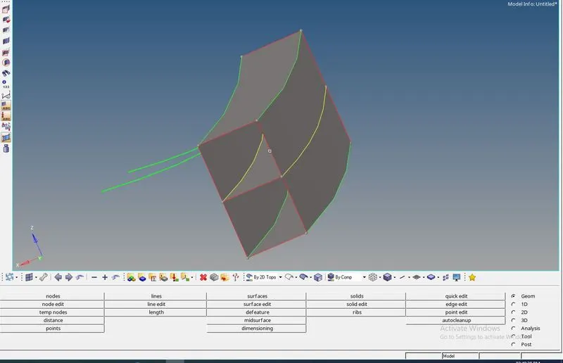
- Now bumper beam upper and lower are attached properly to bumper beam rear and front. But we see bumper beam mid is not attached to bumper beam rear and front.
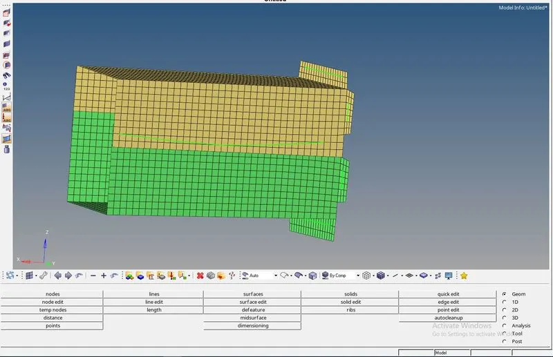
- Go to geom>Surface edit>trim with surf/plane. Select bumper beam mid and bumper beam front. Now you can see a yellow line which mean three surface are joining together. Now we dont have any free surfaces and we can proceed to mesh the beam component. create 2D mesh with 6mm as element size.
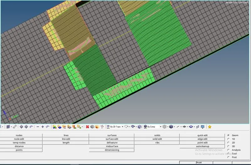
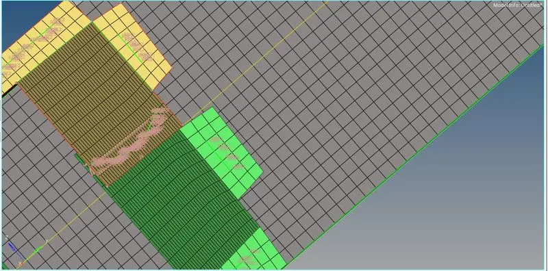
- Follow similar process to create spot weld connections on flanges and join them to bumper beam. RBODY connections are created as shown in figure.
Part 2: CRUSH TUBE
- Import Crush_tube_0000 model. Go to Model>Output Blocks>Create>assign name as Contact. Again create>assign name as Part.
- In contact output block select entity ID as groups>check on TYPE 7 self contact.
- In Part Output block select entity ID as Components> check on all components. Select NUM_VARIABLES as 1 with Default option activated.
- Save the model and Run the Simulation as it is for first case.
- In Second case change Inacti under TYPE 7 self contact to 6 and run the simulation.
- Save the file and proceed to further simulations.
- Now to open hypercrash under Applications. Drag and drop Crash_tube_0000 file.
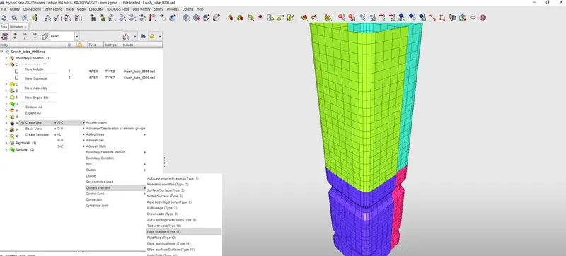
- Create Type 11 Conatct as shown in Fig below.
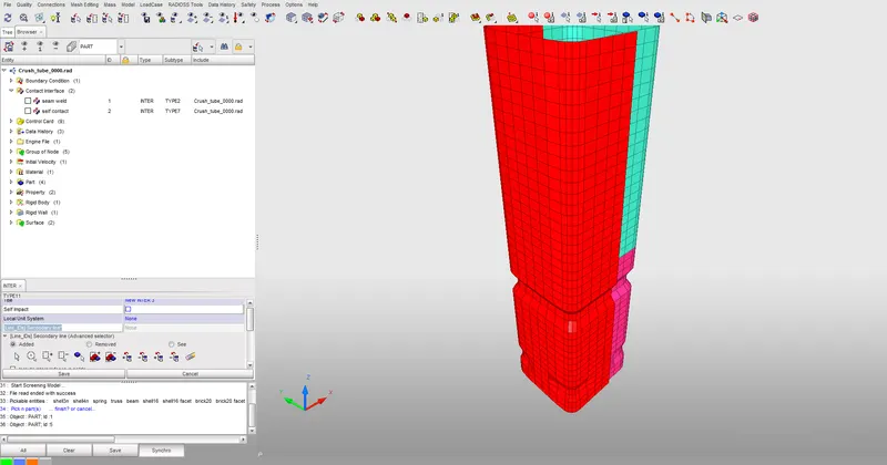
- Under [Line_IDs] Secondary line* Select the option Include Picked parts and select the Highlighted parts in red as shown.
- Under [Line_IDm] Main line* Select the option Include Picked parts and select the Highlighted parts in red as shown
- Hit save option and you can save this file with a different name just to preserve the previous model.
- Click on File Export and select radioss. Give file name and exit hypercrash. Import the same file in radioss under output block contact add Type 11 group to the Contacts and run the simulation.
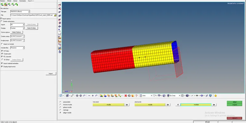
- Now for 4 th case perform some geometry editing. There are multiple ways to remove the notches by using element offset, Node align or translate. We will proceed with Node align option. Select two nodes on the surface of the final location you want the rest of the nodes to be in>then select the nodes to be aligned> hit align. Follow the same process to create a notch free surface component.
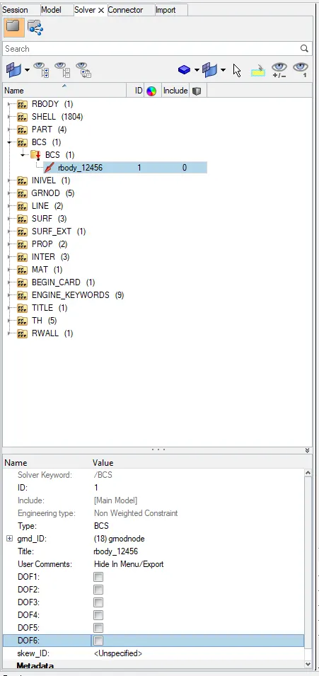
- To remove Boundary conditions go to Solver BCS>rbody>uncheck all DOF. Now run the simulation and proceed to case 6
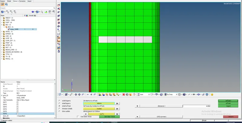
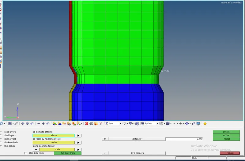
- Go to Element offset under 2D>Shell offset>select shells to create offset value of 4mm>hit offset+
- Run the simulation and follow same procedure to remove this notch and proceed to case 5
- This time select the middle layer of elements to offset and create a new notch in the middle. Run the simulation for case 5
Result Comparison:
Important Interface Parameters:
Igap : Determines how the size of the gap is calculated
Gapmin :Minimum gap for activation of interface
Inacti : Action to take if initial penetrations exist
Istf : Affects how the stiffness of the interface is calculated
Iform : Friction formulation
Stmin : Minimum stiffness to use in the interface
Idel : Update for Deleted Elements Due To Failure
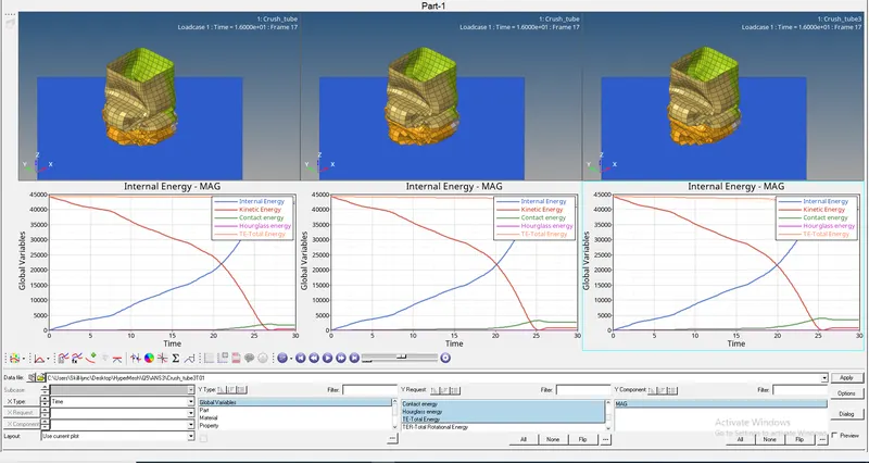
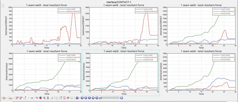
Contact forces: Case1-6
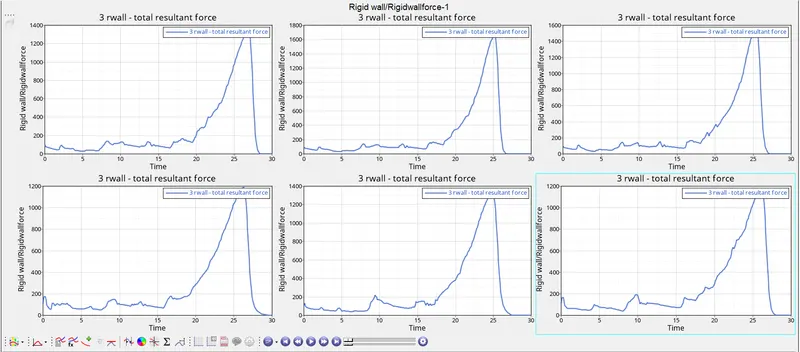
RWALL forces: Case1-6
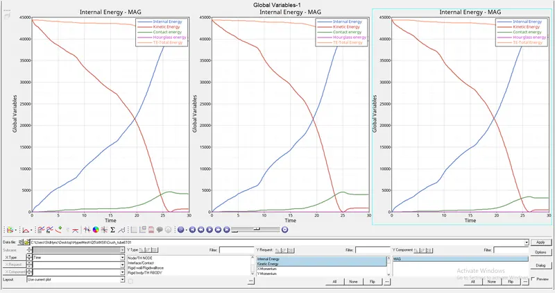
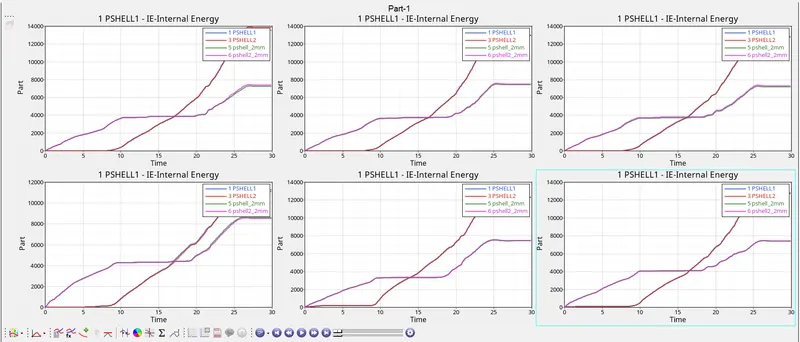
Internal energy: Case1-6.
- The internal energy is slightly higher in first case as compared to all other cases. This might be due high deformations produced in first case.
- Also the elements penetrate into one another causing an increase in energy.
CASE 1 and 2:
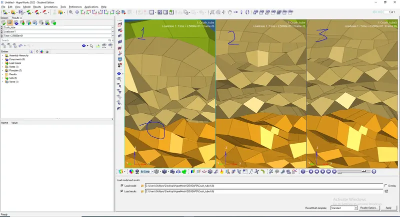
- Penetrations result if a slave node is closer to the master segment than the calculated gap
- Initial repulsion forces give an error in the energy balance due to the interfaces work.
- This diference can be noted in the Crush_tube_0001 OUT file.
- With Inacti as 6 the initial penetration, P0 should be smaller than 30% of the initial gap to avoid contact stability issues.
- Inacti 6 removes initial penetrations where possible. Or else, it reduces to less than 30% of the defined gap value and adjust the gap.
| IGAP value |
Variable Gap (Gapmin =0.5) (gs+gm=ts/2+tm/2=2.5) |
Limitation |
| 0 | Gapmin=min (tm, lmin/2) | NA |
| 1 | Variable Gap=max [Gapmin, (gs + gm)] |
If Gapmin is not specified then Variable Gap = max [Gapmin, (gs + gm)] = max [tm, (tm/2 + ts/2)] Solution: Specify Small Gapmin(i.e Gmin=0.5) |
| 2 | Variable Gap=max {Gapmin, min [Fscalegap*(gs + gm), Gapmax]} |
In case of self-impact definition, there is an initial penetration when the gap value is larger than the mesh size This situation can be solved with Igap= 3 or with the flag Irem_gap = 2 |
| 3 | Variable Gap = max {Gapmin, min [Fscalegap*(gs + gm), %mesh_size*(gs_l+gm_l), Gapmax]} | NA |
FIG1:
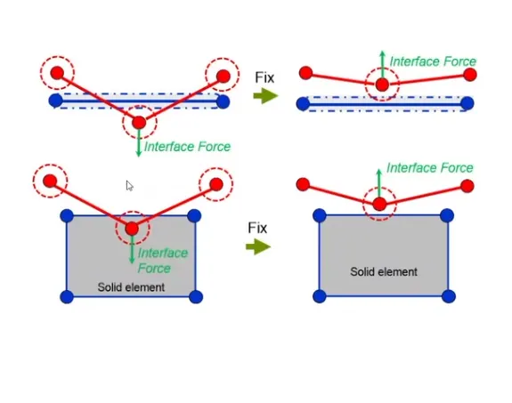
FIG2:
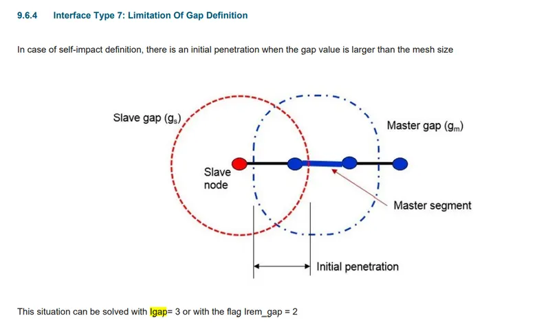
FIG3:
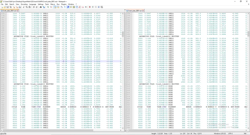
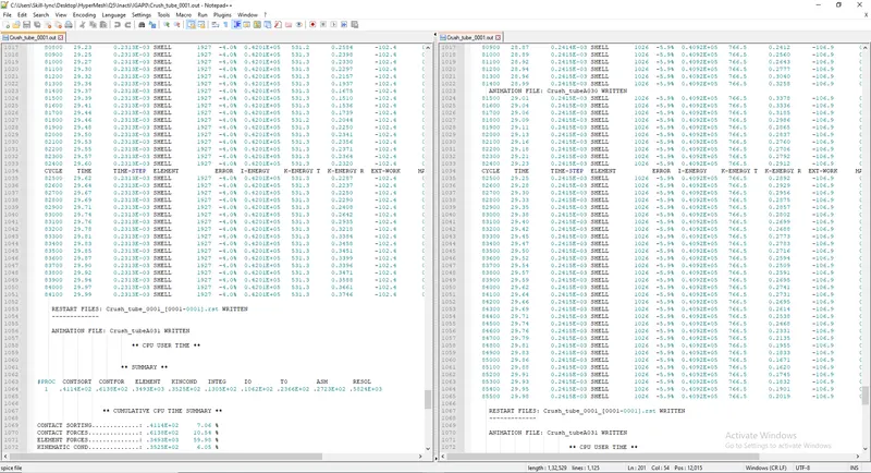
FIG4:
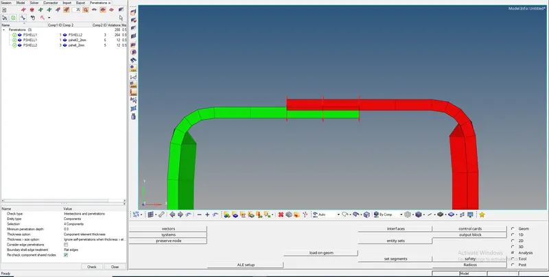
FIG5:
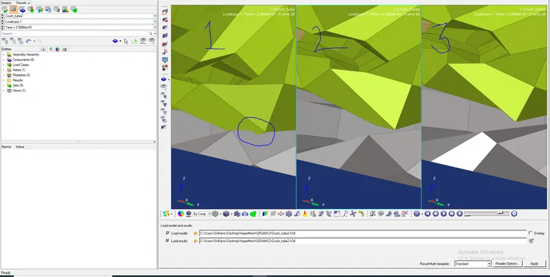
FIG6:
CASE 3:
- There are situations where the Type 7 node to surface interface will not detect the contact due to edges crossing each other at
angles. Type 11 interface can be added to capture the physics correctly.
FIG7:Penetrations for challenge 3
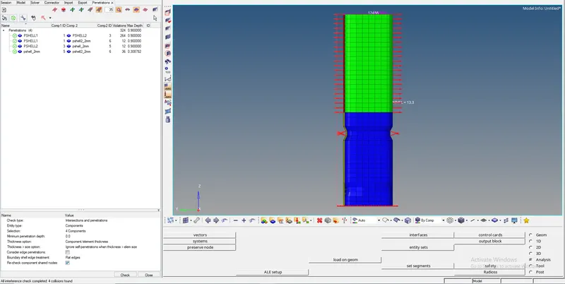
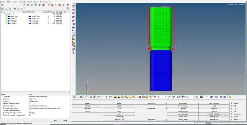
FIG8:Penetrations for challenge 5
CASE 4-6:
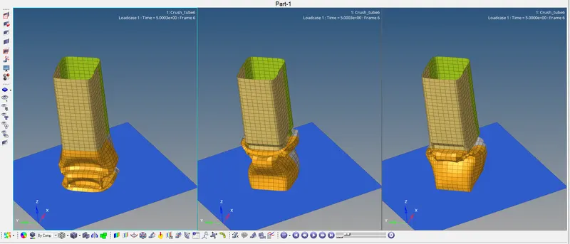
- Notches play an important role in how the structure of the component fails.
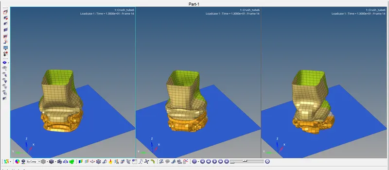
- From the image/animation step comparison you can see that the component with notch in the middle fails first at the notched part and top part crumbles down when the bottom portion is completely deformed.
- The latter deformation will depend on formerly deformed elements as seen in second figure but mostly the deformation is not as different as seen in first half.
PLOT OF ENERGIES:
No Significant change is seen in case of Contact energy, Kinetic energy or internal energy in comparison with other cases.