Assignment 5-RADIOSS Interfaces & Study of Effect of Notches Challenge
- Objective: To mesh the given bumper model with mesh size of 6 mm.
To run the crash tube simulation with given 6 cases and plot the graph for energies.
- Procedure to mesh the bumper:
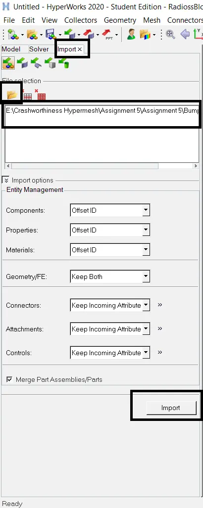
Import the .hm file. Go to File > Import > model. Click on Select File icon. Select the .hm file and click on Import.
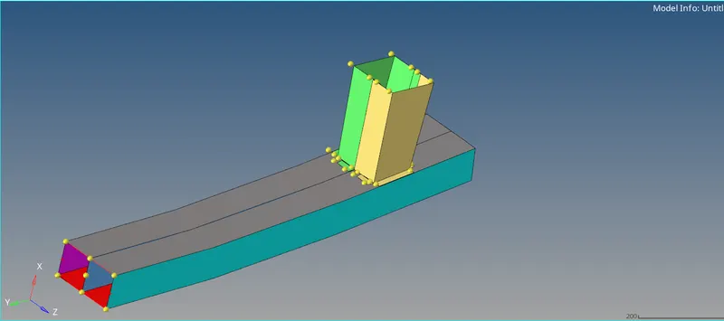
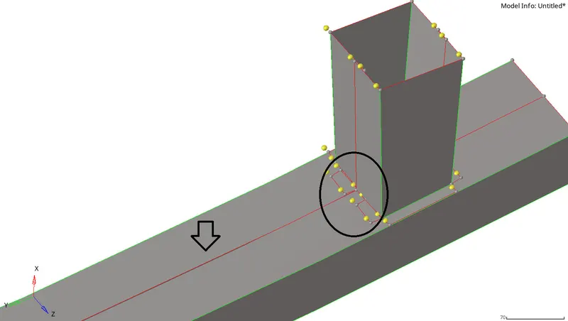
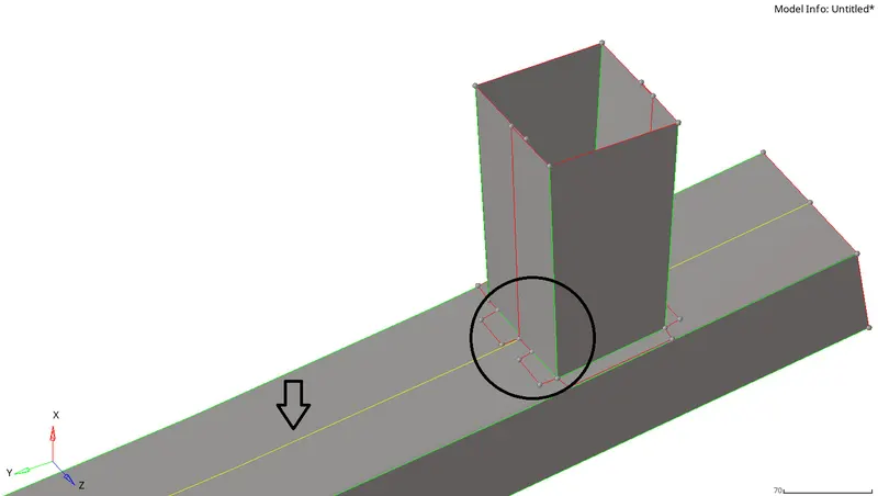
Switch to By Topo geometry color mode. Few free edges are found. These are easily fixed by using surface edit tool and edge edit tool available under Geom page.
Go to Preferences > Criteria File Settings > Target element size. Enter Target element size = 6. Now press F12 to go to automesh panel. Enter element size =6 and mesh type to 6.
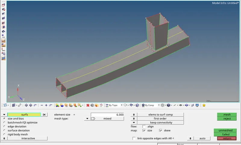
Perform the meshing manually surface by surface.
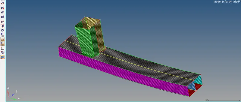
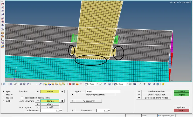
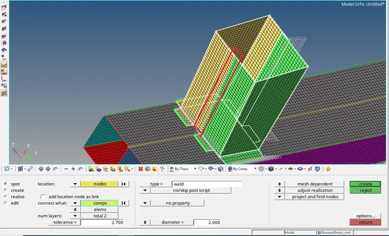
Now connect the crash boxes with the bumper using spot weld. Go to 1D > connectors > spot > spot. In the location selector, select the nodes of the crash box. In connect what selecctor, select the
components to be connected, i.e crash box and bumper rear. enter no. of layers = 2 and search tolerance as 2.5. Select type as weld with diameter = 2 and click on create. The connectors will be created as
seen below.
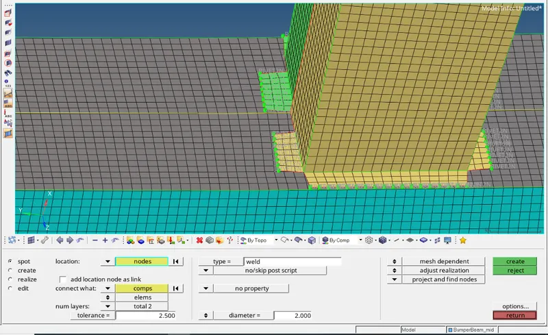
Similarly connect the crash boxes.
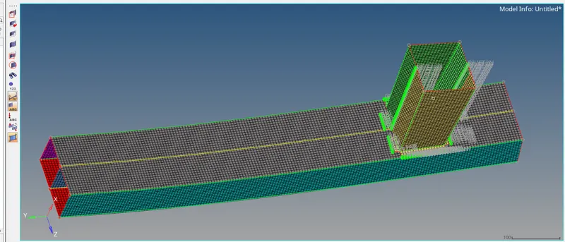
Thus, meshing is done on the bumper and the crash boxes are connected to the bumper using 1D connectors.
Now we can proceed to run the simulation for the given crash tube.
- Case 1:
We have to run the simulation as it is with no changes. Open Hypermesh with user profile as Radioss. To import the 0000.rad file, click on File > Import > Solver deck and import the file.
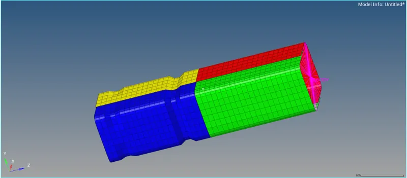
After importing the file, we can check the defined interface in the model.Type7 interface is used. It is a general purpose interface which can simulate all types of impact between a set of nodes and a master
surface. Major advantage of Type7 interface is that it is non oriented and slave nodes can belong to the master surface enabling self impact. Following are the defined parameters in the model -
- Istiff = 4 (affects how the stiffness is calculated)
- Igap = 0 (determines how the size of gap is calculated)
- Gapmin = 1 (min. gap for activation of interface)
- Iform = 2 (stiffness based formulation for sliding forces)
- Iacti = 0 (action to take if initial penetration exists)
- Stmin = 1 (min thickness in the contact to avoid too soft contact)
Istiff = 4 will set the stiffness of interface based on the softer of master and slave.
Igap = 0 will take the size of gap defined by Gapmin.
Iacti = 0 will take no action against initial penetrations, if any.
To run the simulation, go to Analysis > Radioss. Using the save as option, give the destination to where the file is to be saved. Toggle the export options to all and run options to analysis.
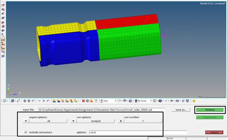
Click on Radioss. The simulation will start running.
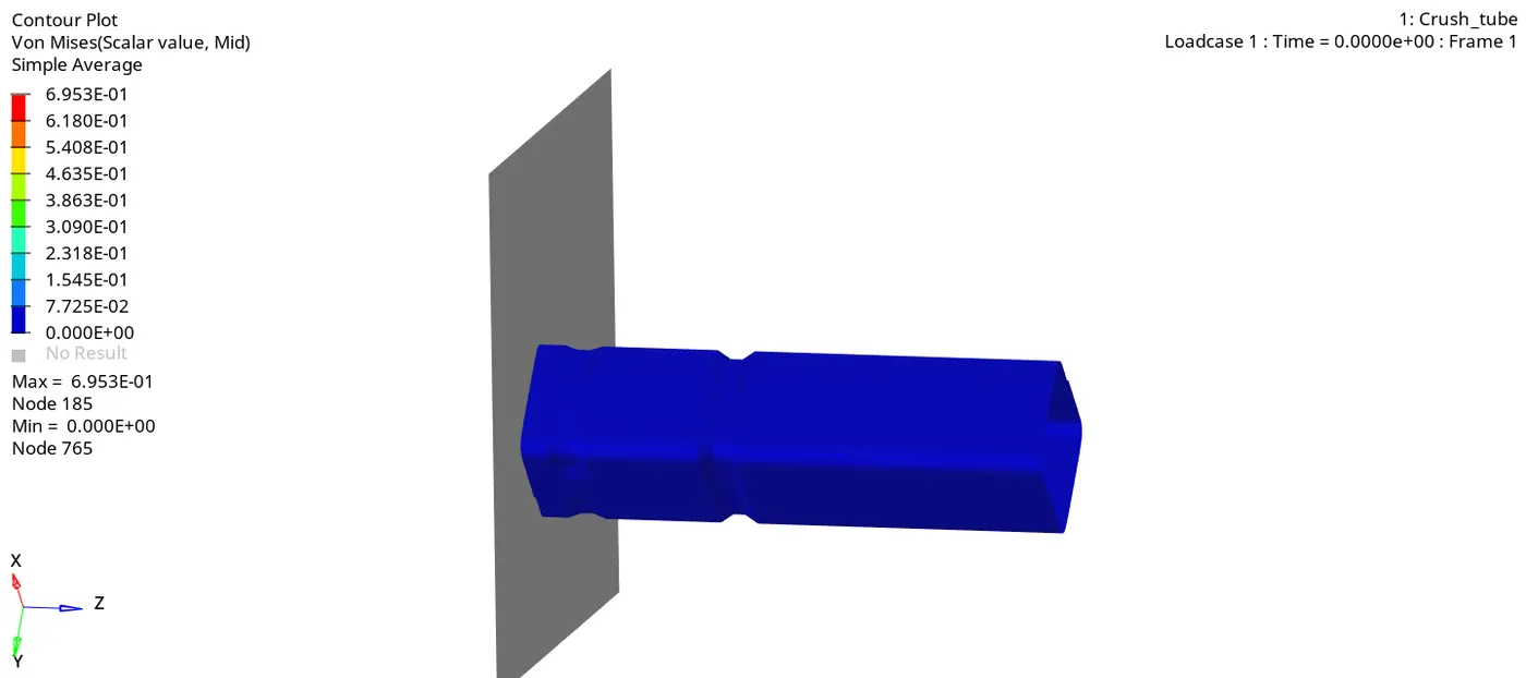
As seen below, having a notch in the crush tube affects the way the model deforms. After hitting the rigid wall, the crush tube deforms in the area of notch first and then deforms further.
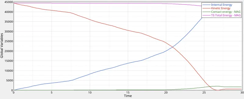
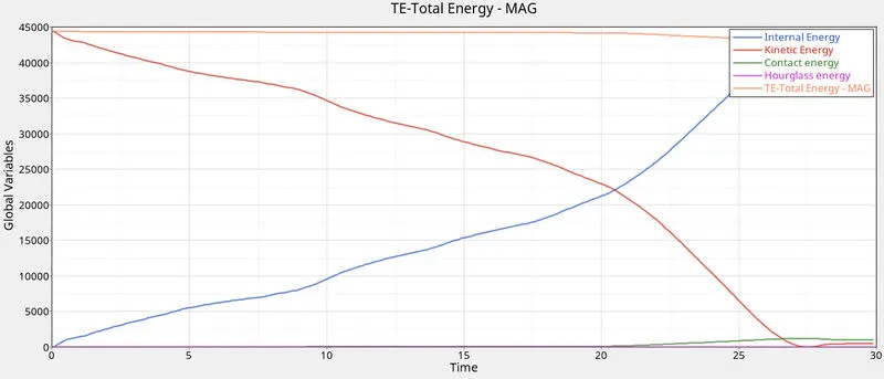
As seen in the graph, the kinetic energy is maximum at the beginning which starts decreasing once the crush tube impacts the rigid wall. This energy is converted into strain energy as the crush tube deforms
as observed by the increase in internal energy of the system. Energy error is about -3.8% which is acceptable. A part of total energy is used by the contact energy as seen in the graph. As total energy
reduces, contact energy increases. Contact energy = contact force*distance moved to avoid penetration. The contact force is basically the energy spent by enabling a contact force to avoid penetration. This
should be minimum. As seen above,the contact energy is very less for most of the time and there is slight increase in the contact energy at the end of simulation.
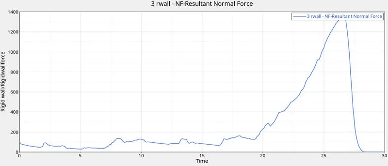
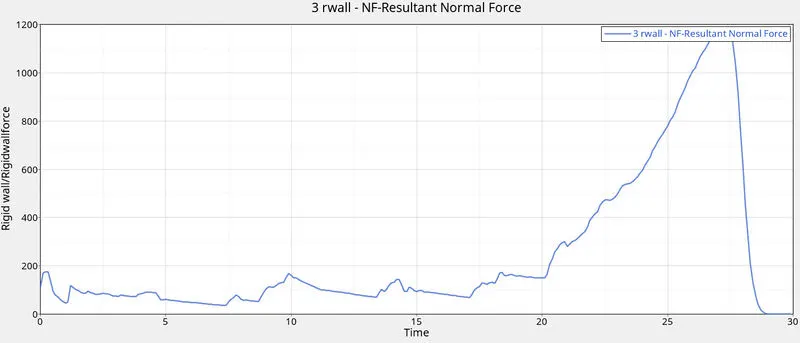
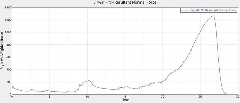
For rigid wall, there is sudden rise in the peak value of rigid wall force after T=25. By this time, the crush tube is completly crushed and therefore the deformed model having no further scope for deformation
gets pushed against the wall with some velocity to which the rigid wall reacts.
- Case 2:
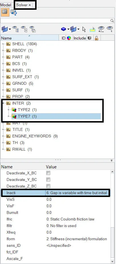
In this case, we have to change the Inact = 0 to Inacti =6. Inacti = 6 will remove any initial penetration present. Elsewhere, it wiill reduce the defined gap to less than 30% of the defined value and adjust the
gap.To change the Inacti to 6, click on Solver browser > Interface> Type7 > Inacti. Set it to 6.
After this, run the simulation. The procedure is same as discussed earlier.
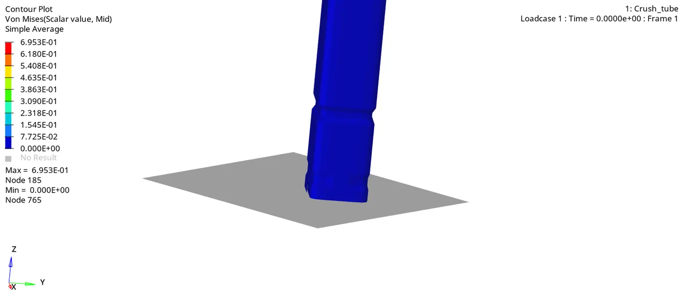
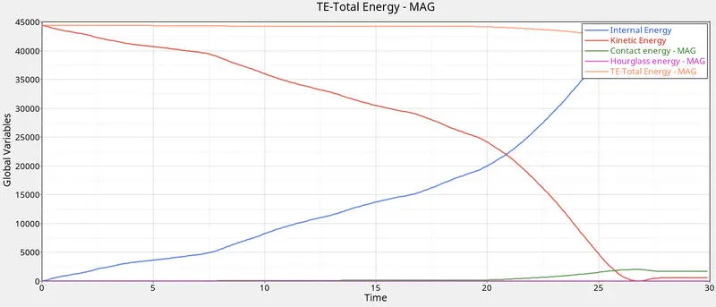
The nature of deformation and the energy graph are similiar in nature compared to case 1. Energy error is -3.8% which is acceptable.
- Case 3:
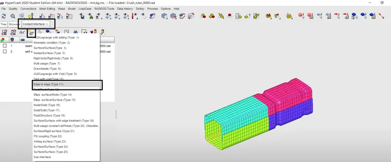
In this case, we have to create Type11 contact and run the simulation. To create the contact, we will use Hypercrash, which is a specialized preprocessor for Radioss. After importing the file,
go to Loadcase > Contact interface. Click on create icon and select Edge to edge (Type11). Type11 interface is defined by identifying master and slave lines. This contact, when added with
Type 7 can help to capture the physics correctly. This is very helpfull in case of edges crossing where the nodes of the element are far away and the element is in close proximity of another
surface.
Type 7 uses penalty method in Interfaces which treat the behaviour between slave nodes and master segments as springs that generates resistive force as a function of penetration. Type 11
works in similar manner as Type 7 in terms of penalty formulation, gap definition and search method.
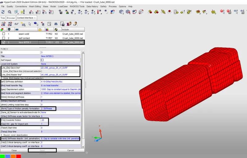
After settting all the recommended values (same as Type7), we can export the file and open it in Hypermesh and run the simulation.
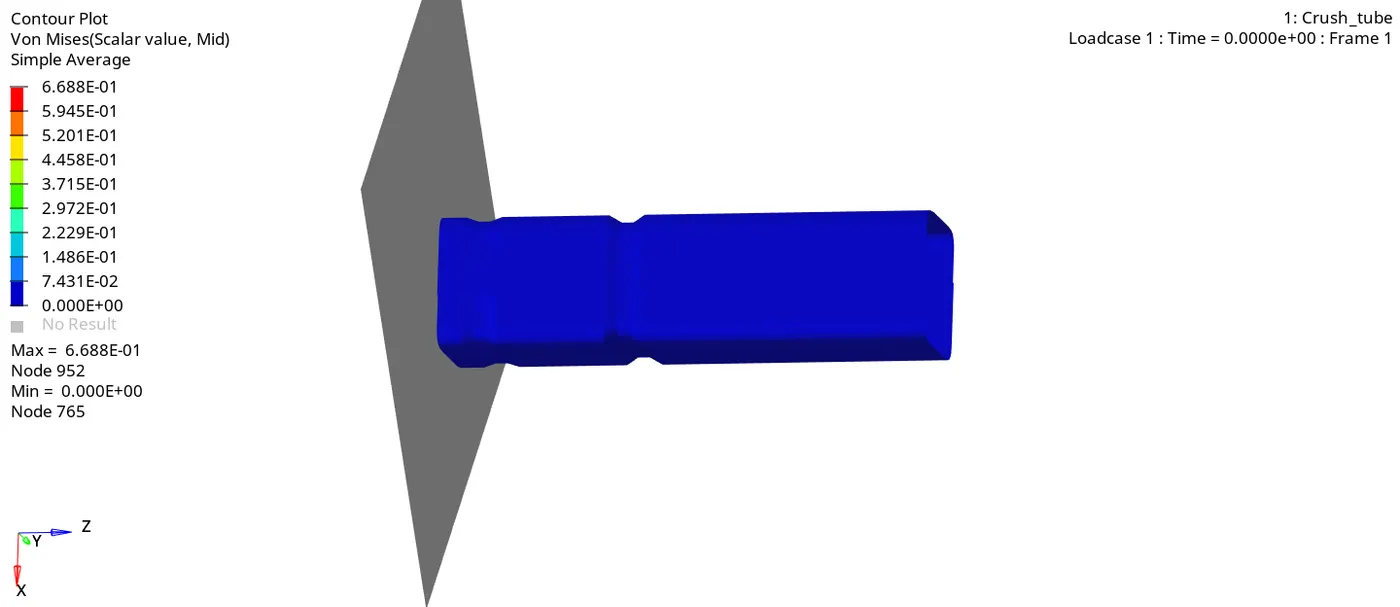
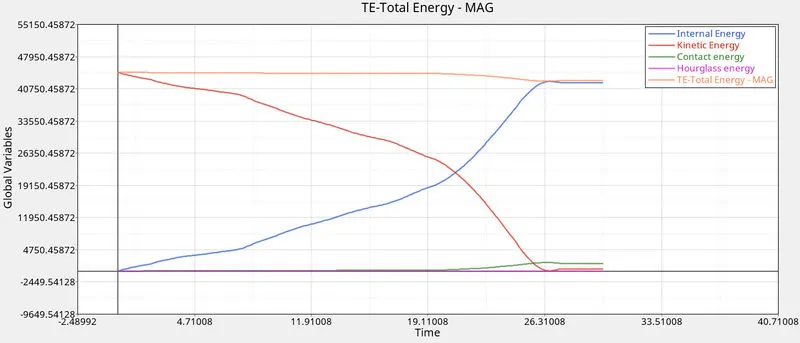
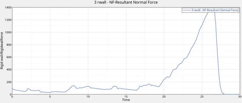
Here too, the nature of deformation and energy graph nature are similiar as previous case. The notched portion is first to deform. Energy error is about -3.8% which is acceptable.
- Case 4:
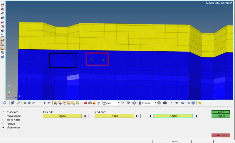
Here, we have to remove both the notches and the boundary conditions on the rigid body and run the simulation. To remove the notches, we can use align option from the node edit option available under
Geom page. Go to Geom > node edit > align. In the 1st and 2nd end selector, select two nodes (black) respectively, which will define a line along which the selected nodes on the notch (white) will be placed,
thus removing the notch. Click on align. The nodes will be aligned as seen below. Repeat the same procedure for the entire notch.
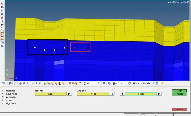
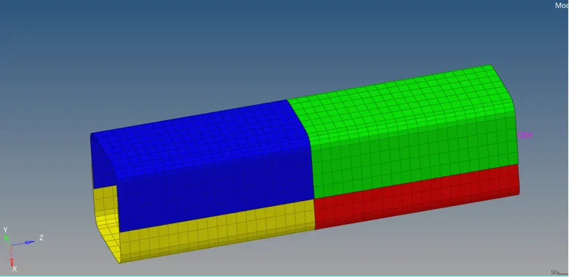
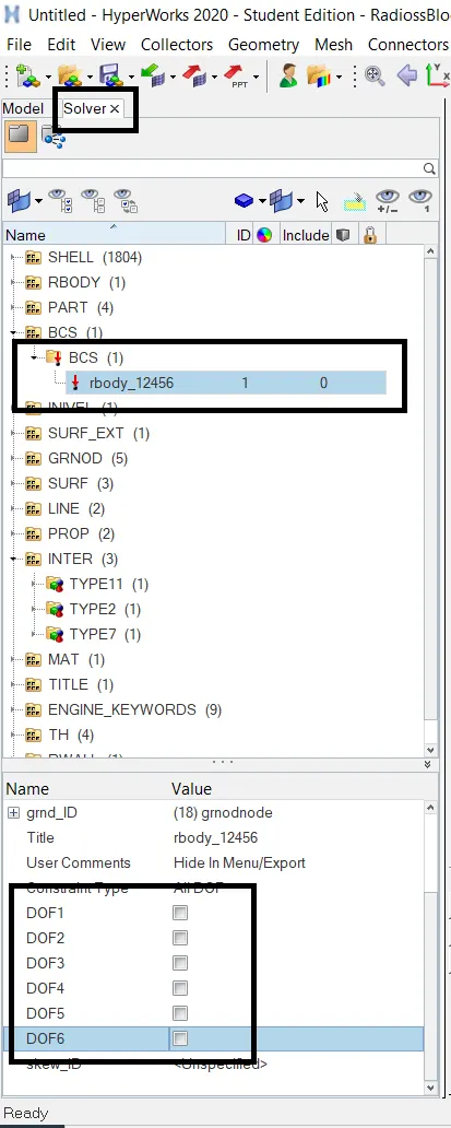
To remove the boundary conditions on the rigid body, go to Solver > BCS > BCS > rbody_12456. Uncheck DOF1, DOF2, DOF3, DOF4, DOF5, DOF6 which will allow translation in X, Y, Z and rotation in X, Y, Z
direction respectively.
Now run the Simulation.
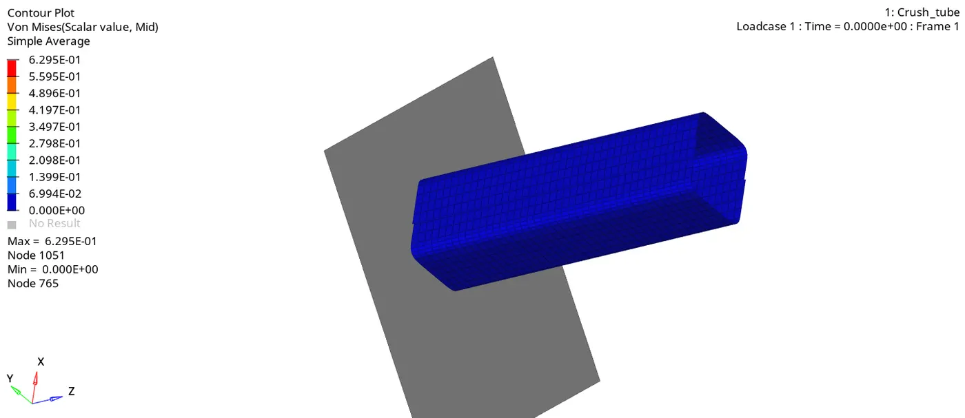
As seen here, there no notches on the crush tube. During impact, there is no localized deformation as there are no notches present and the deformation progresses as expected. The nature of energy graph
is also similiar to previous case. Energy error is about -2.4% which is acceptable.
- Case 5:
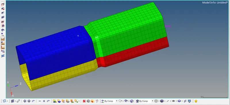
In this case, we have to create a new notch in the centre and run the simulation. We can create notch by using translate option available under Tool page. To properly create the notch, use the N1,N2,N3
option to define the plane of translation. Translate the nodes by 4mm and create the notch.
Once completed, run the simulation.
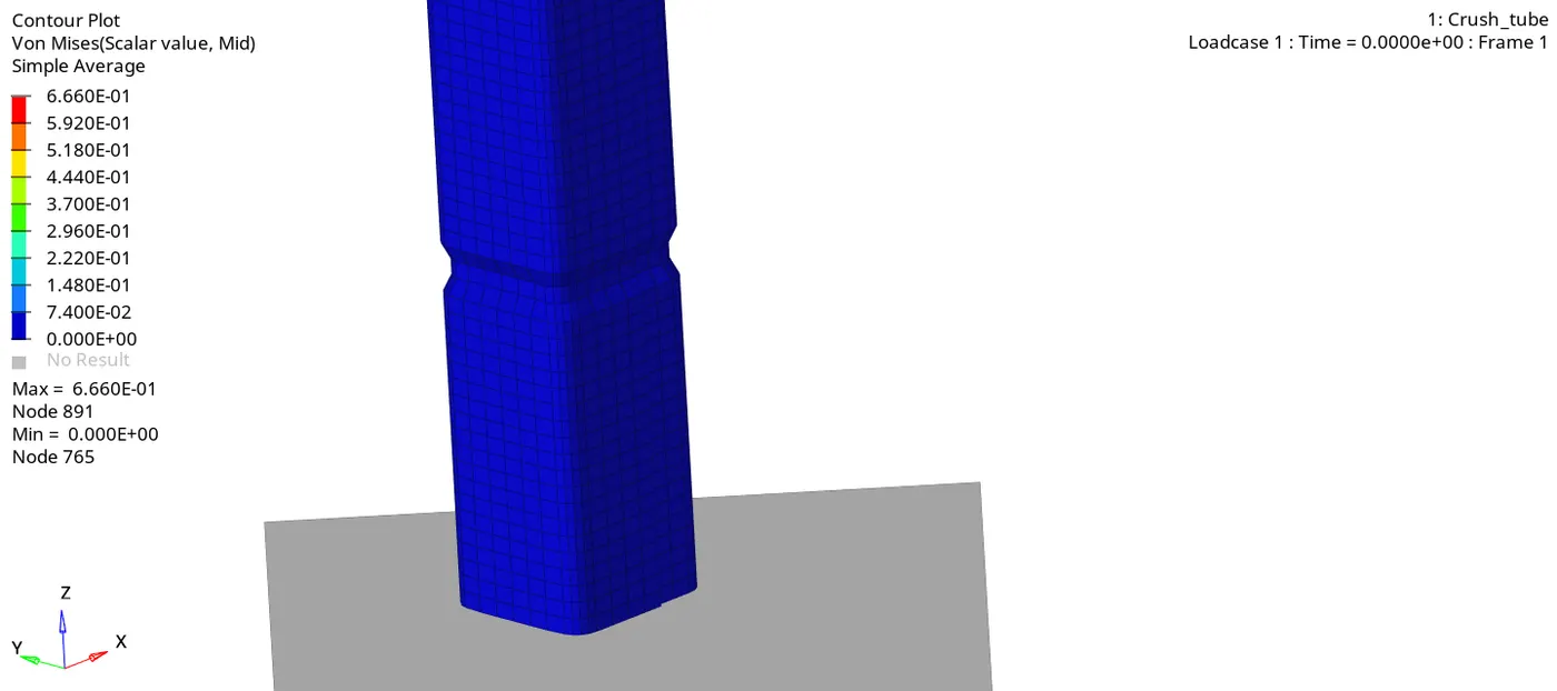
Also here, after impact,deformation is first observed in the middle in the portion where the notch is.
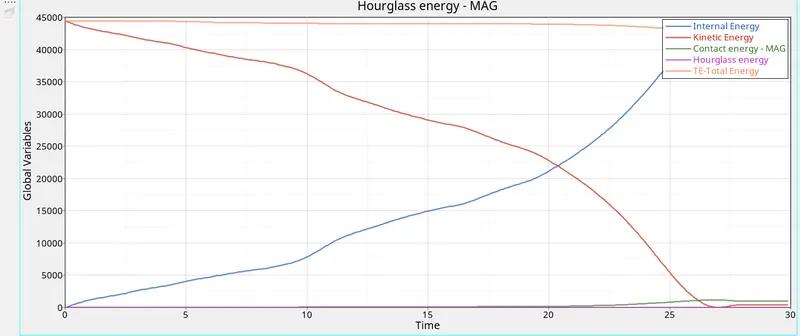
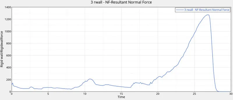
The nature of deformation and the energy graph are similiar in nature compared to previous cases. Energy error is about -2.3% which is acceptable.
- Case 6:
Create notches on two opposing surfaces and run the simulation. The procedure to create notch is the same as discussed earlier using Translate tool.
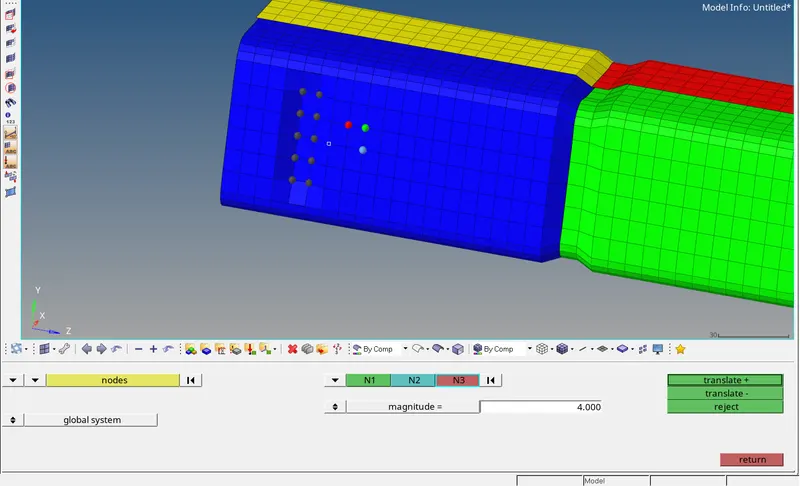
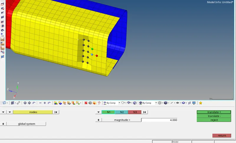
Now run the simulation.
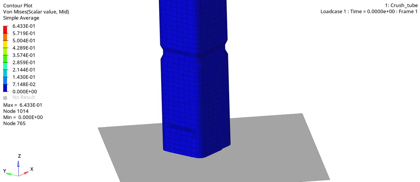
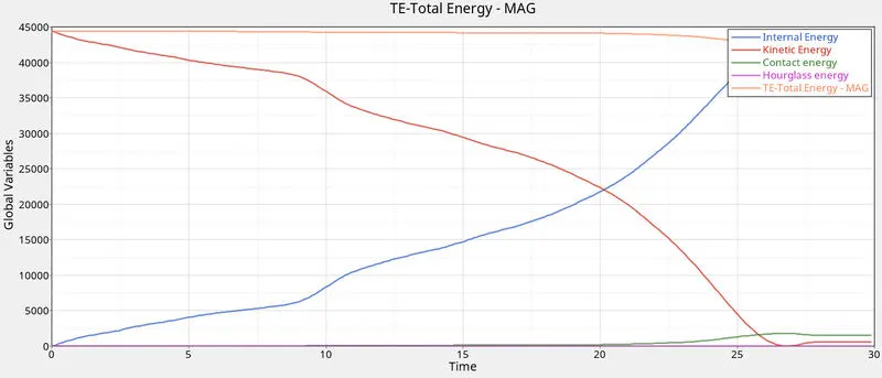
Deformation is first observed in the notched region and the energy graph is similiar in nature compared to previous cases. Energy error is about -3.5% which is acceptable.
- Conclusion:
It is observed that in case 4 where the notch is removed, the stress induced in the crush tube is the least compared to other cases. The crush tube with notches undergo stress concentration and these
areas are the first to undergo deformation. The deformations are predictable in case of notched components. No initial penetration is observed in case 1 where Inacti = 0. If initial penetration existed,
it could have been indicated by the graph of contact energy which could have piked up at the start itself before any impact. Energy error for all cases is between -3.8% to -2.3% which is acceptable.