COMPARISON OF CONTACT INTERFACES IN HYPERMESH
Objective:
To create the mesh for the bumper assembly and establish connections and to analyse different type of contact surfaces and compare their results .
Procedure :
To create mesh for Bumper assembly:
1. Import the given model into hypermesh
2. Perform geometric cleanup on the model.
3. Create the mesh using Automesh option available in 2D panel.
4. Establish the connection using connectors option available in 1D panel.
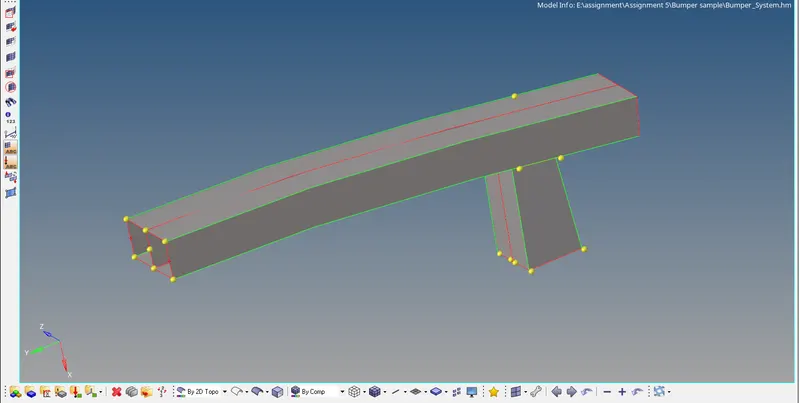
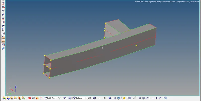
Given model before geometric cleanup:
After Geometric cleanup:
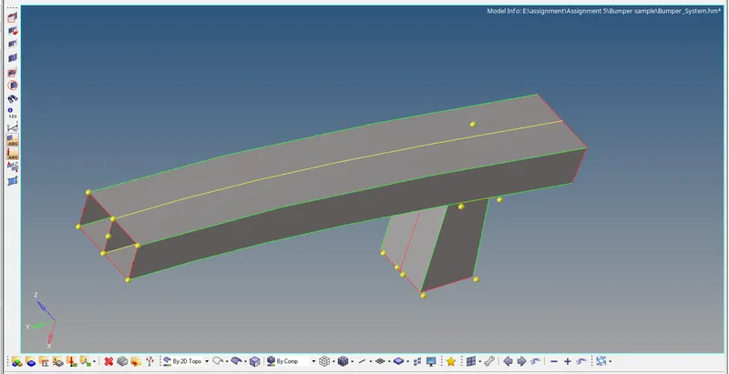
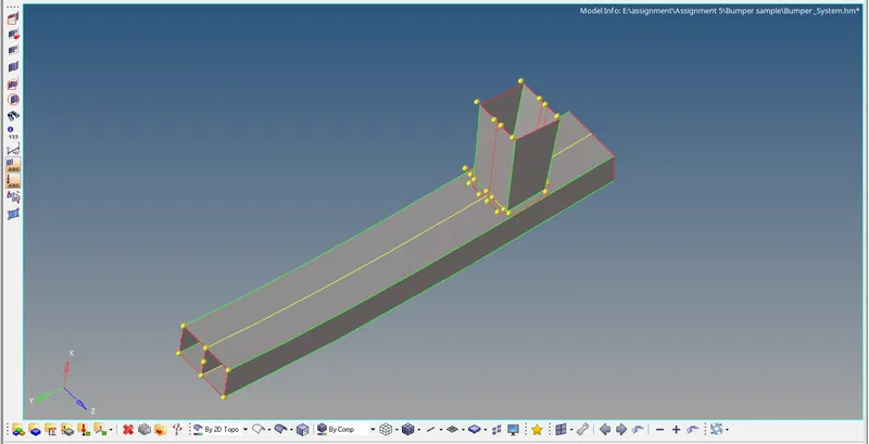
- In geometric cleanup temporary nodes, unnecessary lines are deleted and surfaces are joined using extend options available in Quick edit option available in Geometry panel.
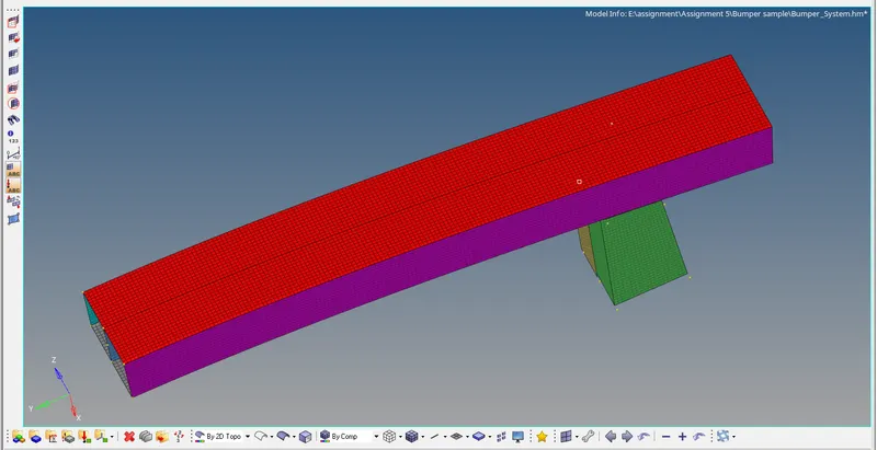
- After the completion of geometric cleanup, the model proceeds for the meshing process which is in 2D panel
2D`rarr`Automesh `rarr` Surfaces`rarr` Displayed `rarr` Element size (6mm) `rarr`Mesh
Meshed model:
Connections:
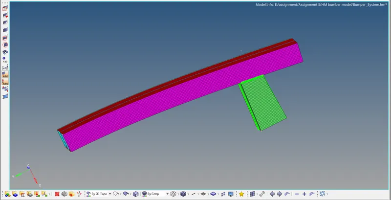
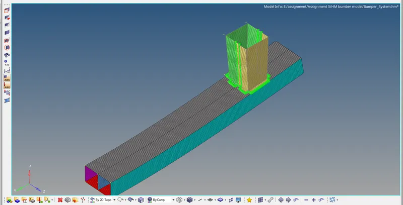
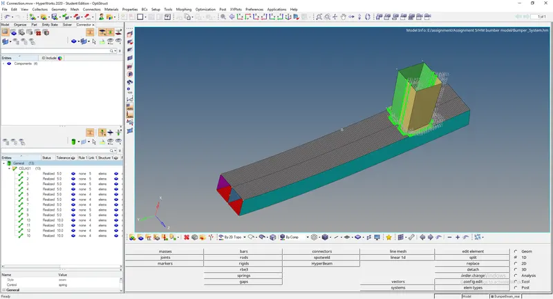
- Since the given components needed to be connected, connector option under 1D panel is used.
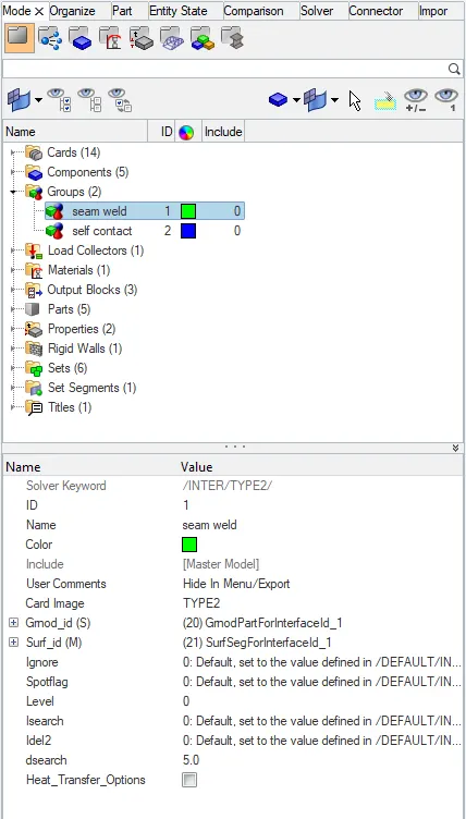
- In 1D panel, the connectors is selected then in the list of options available Seam weld option is selected.
- Here parameters like tolerance and space are needed to be mentioned where tolerance is the space between the components and Space is the distance between the connections which are to be created.
- To check whether the connections are established, in the View menu under the browser in hypermesh option connectors is selected to view whether the connections is established.
Contact Interface of Crash tube:
CASE SETUP AND EXECUTION:
Case 1: Run the crush tube model as it is
- Import the given crush tube model into hypermesh
- no change is to be done to the model.
- the initial properties, material, and type of contact used are observed.
- Click on the analysis panel in the hypermesh.
- Save the model in the local directory.
- Click the RADIOSS button then run the base simulation.
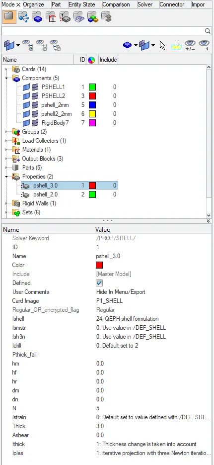
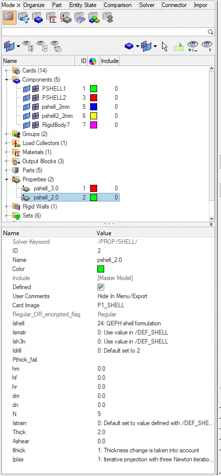
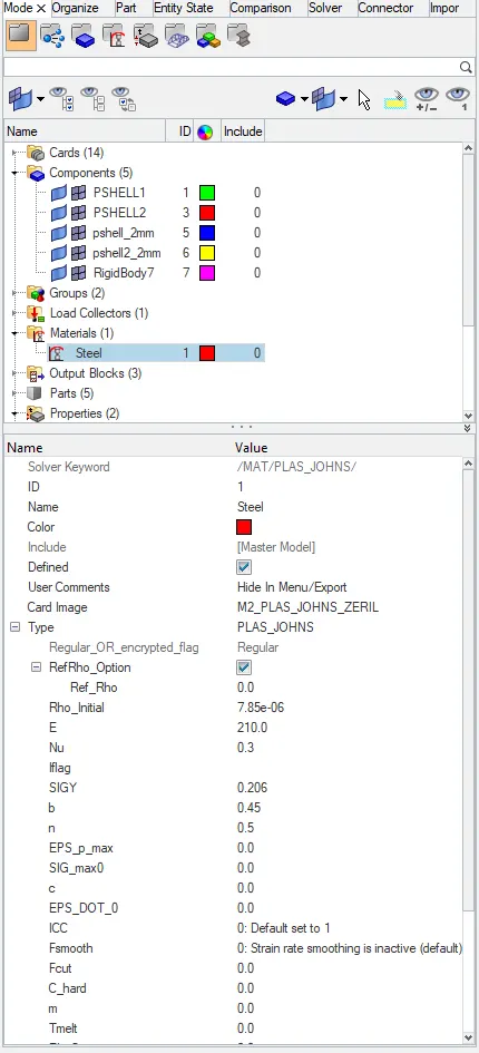
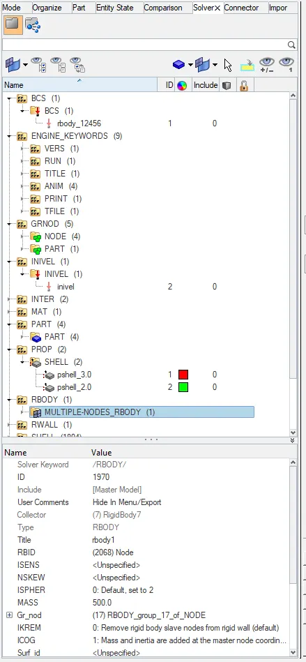
Open the file "Crush_tube_0001" in notepad to check Energy error, mass error and time elapsed.
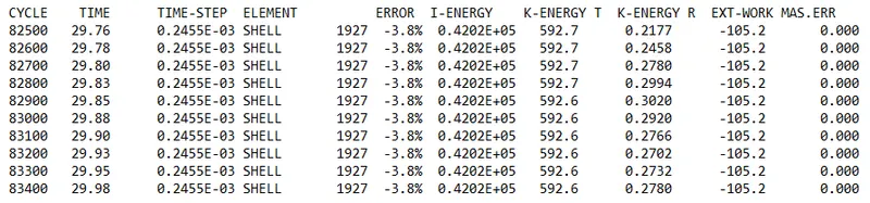
as the energy error is -3.8% which is less than 15% so it is acceptable, also the mass error is found out to be 0.000
Since the energy error is acceptable, the model is moved for further observations by changing the environment to hyper view, then importing the file "Crush_tube.H3d"
Displacement observation:
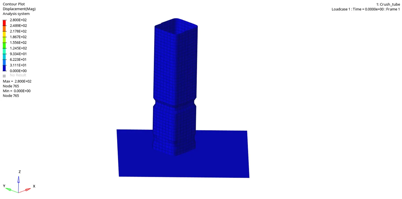
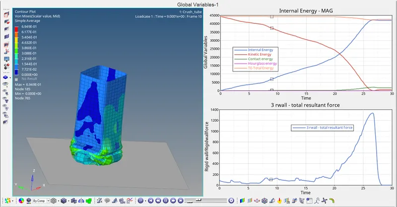
Maximum displacement: 2.800E+02 is at node 765
Minimum displacement: 0.000E+00 is at node 765.
Von-mises Stress Observation:
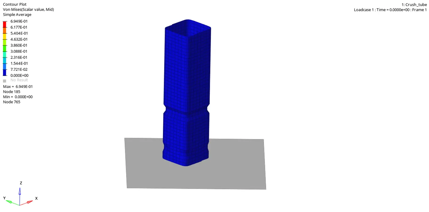
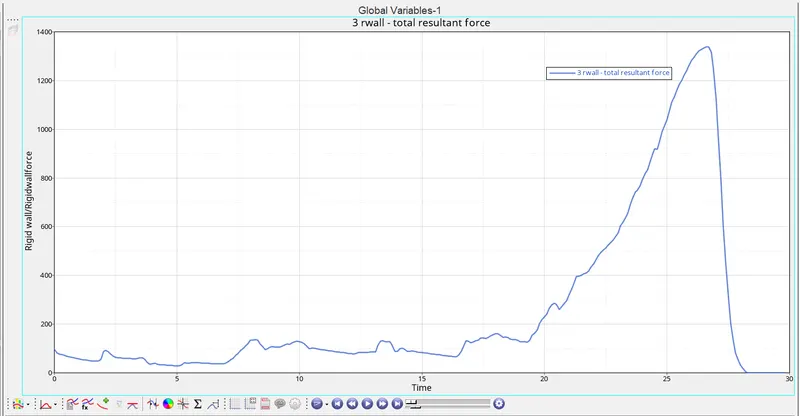
Von-mises stress shows the maximum peak value of 6.949E+01 is at node 185
Von-mises stress shows the minimum value of 0.00E+00 is at node 765.
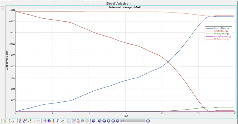
Graph 1: Time versus Internal energy, Kinetic energy, Contact energy, Hourglass energy and Total energy
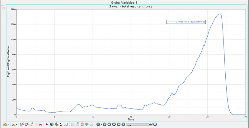
Graph 2: Time versus Rigid wall forces
Case 2: Change the Inacti = 6 and run
- Import the given crush tube model into hypermesh
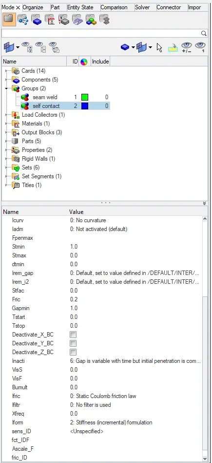
- Change the inacti = 6, which can be used to reduce and scale the gap is one of the methods for removing initial penetration
- The properties, material, and type of contact used are observed.
- Click on the analysis panel in the hypermesh.
- Save the model in the local directory.
- Click the RADIOSS button then run the base simulation.
Open the file "Crush_tube_0001" in notepad to check Energy error, mass error and time elapsed.
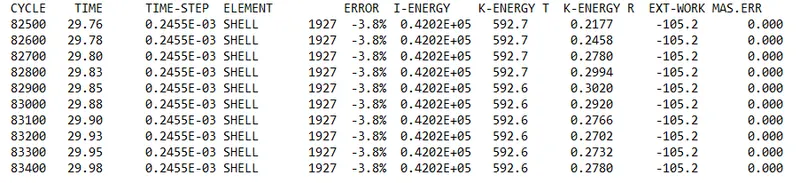
as the energy error is -3.8% which is less than 15% so it is acceptable, also the mass error is found out to be 0.000
Since the energy error is acceptable, the model is moved for further observations by changing the environment to hyper view, then importing the file "Crush_tube.H3d"
Displacement observation:
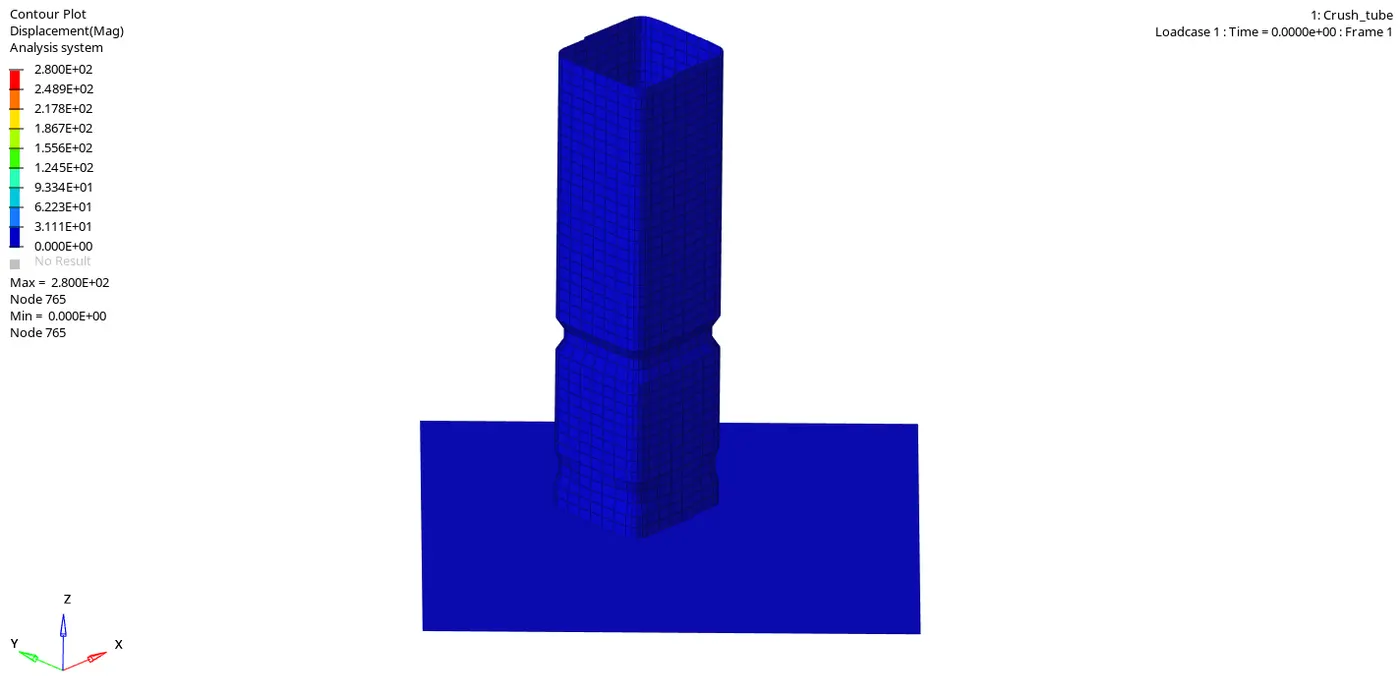
Maximum displacement: 2.800E+02 is at node 765
Minimum displacement: 0.000E+00 is at node 765.
Von-mises Stress Observation:
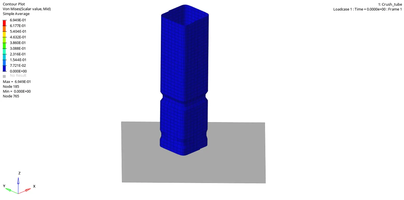
Von-mises stress shows the maximum peak value of 6.949E+01 is at node 185
Von-mises stress shows the minimum value of 0.00E+00 is at node 765.
Graph 1: Time versus Internal energy, Kinetic energy, Contact energy, Hourglass energy and Total energy
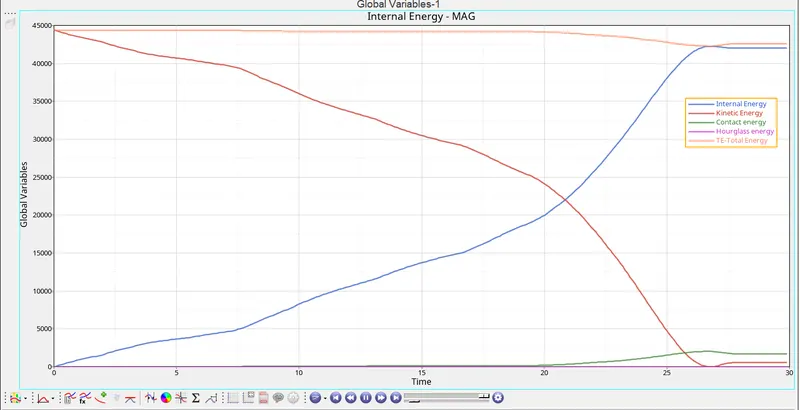
Graph 2: Time versus Rigid wall forces
Case 3: Create type 11 contact and run
- Import the given crush tube model into hypermesh
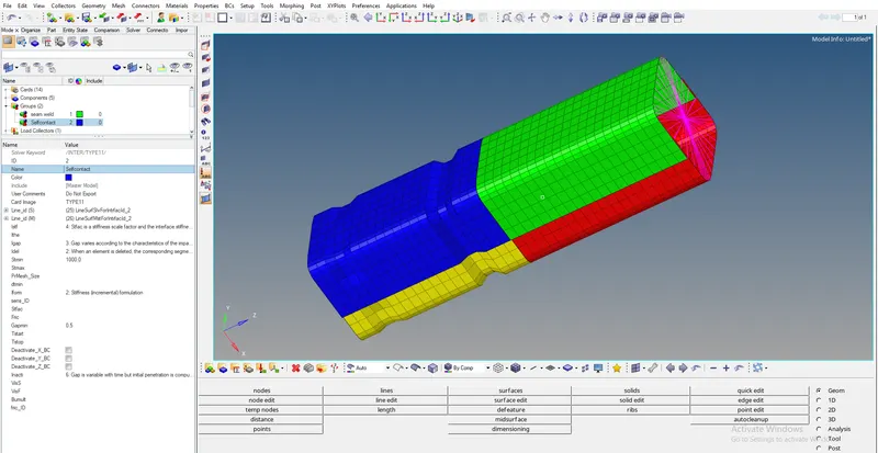
- Change the contact from type 7 to type 11, this can be done by using both hypermesh and hypercrash. also the recommended properties of type 7 are entered.
- Click on the analysis panel in the hypermesh.
- Save the model in the local directory.
- Click the RADIOSS button then run the base simulation.
Open the file "Crush_tube_0001" in notepad to check Energy error, mass error and time elapsed.
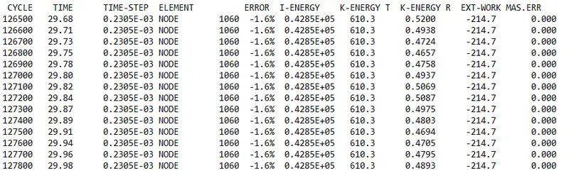
as the energy error is -1.6% which is less than 15% so it is acceptable, also the mass error is found out to be 0.000
Since the energy error is acceptable, the model is moved for further observations by changing the environment to hyper view, then importing the file "Crush_tube.H3d"
Displacement observation:
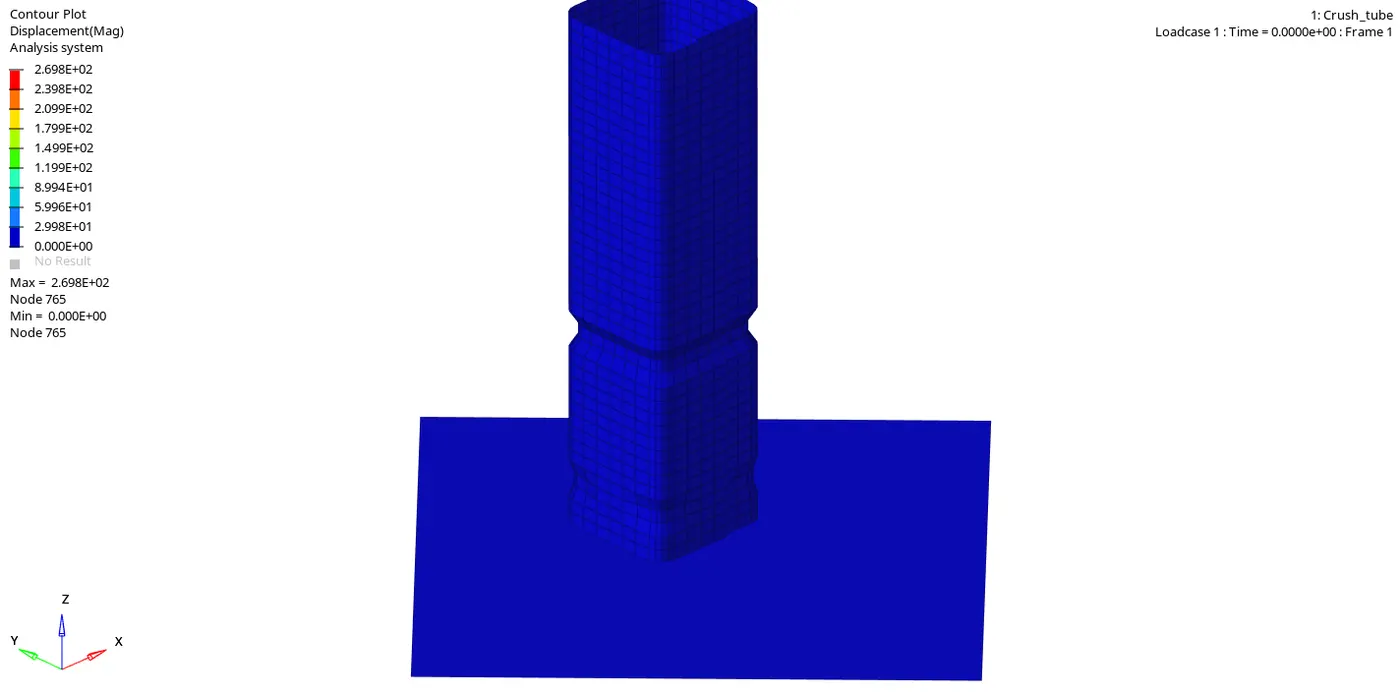
Maximum displacement: 2.698E+02 is at node 765
Minimum displacement: 0.000E+00 is at node 765.
Von-mises Stress Observation:
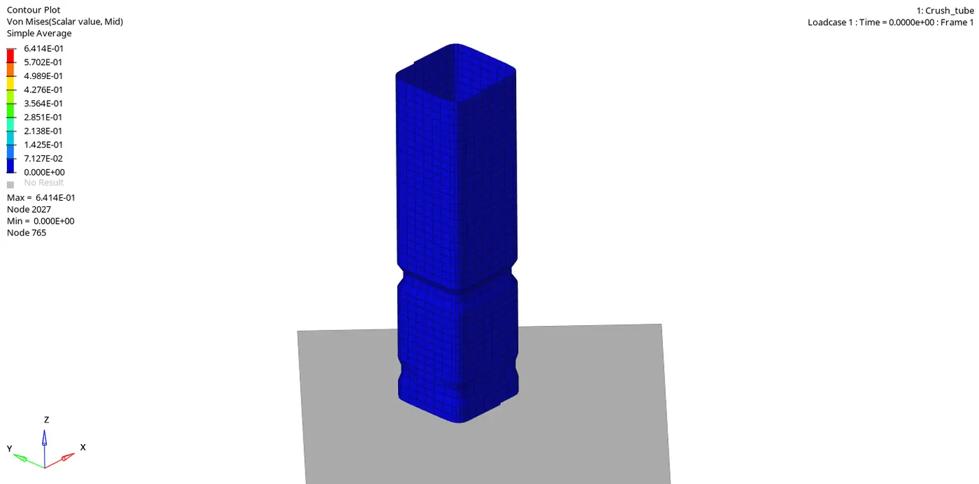
Von-mises stress shows the maximum peak value of 6.414E+01 is at node 2027
Von-mises stress shows the minimum value of 0.00E+00 is at node 765.
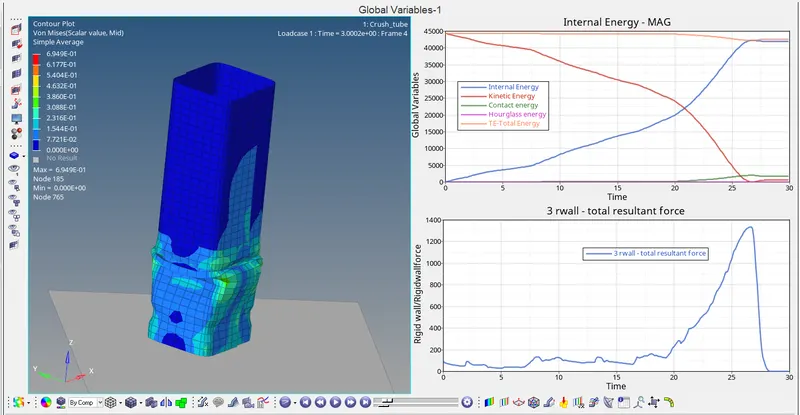
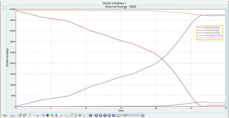
Graph 1: Time versus Internal energy, Kinetic energy, Contact energy, Hourglass energy and Total energy
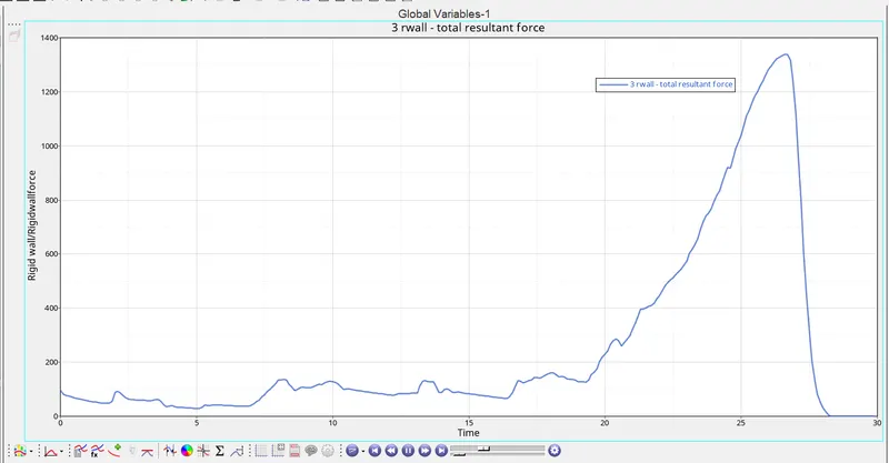
Graph 2: Time versus Rigid wall forces
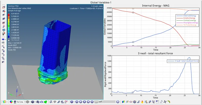
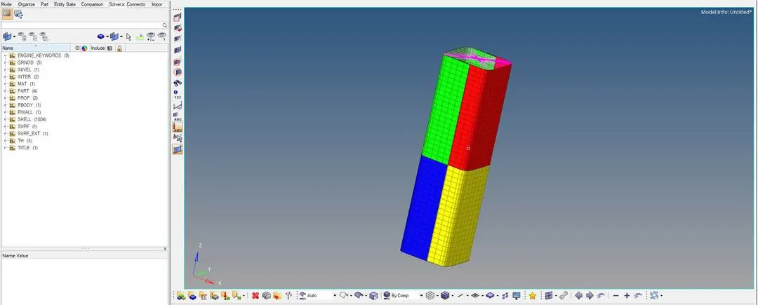
Case 4: Remove both notches and remove boundary conditions on rigid body node then run
- Import the given crush tube model into hypermesh
- In this case, the notches which are found in the model is removed which can be done by aligning the nodes using node edit option available under geometry panel
- The boundary conditions can be removed simply by deleting the BC menu which is available in View `rarr`Browser `rarr`Hypermesh `rarr`Solver
- Click on the analysis panel in the hypermesh.
- Save the model in the local directory.
- Click the RADIOSS button then run the base simulation.
Open the file "Crush_tube_0001" in notepad to check Energy error, mass error and time elapsed.
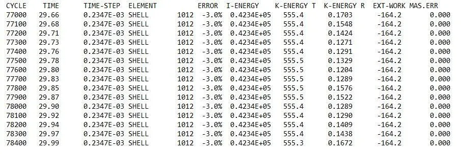
as the energy error is -3.0% which is less than 15% so it is acceptable, also the mass error is found out to be 0.000
Since the energy error is acceptable, the model is moved for further observations by changing the environment to hyper view, then importing the file "Crush_tube.H3d"
Displacement observation:
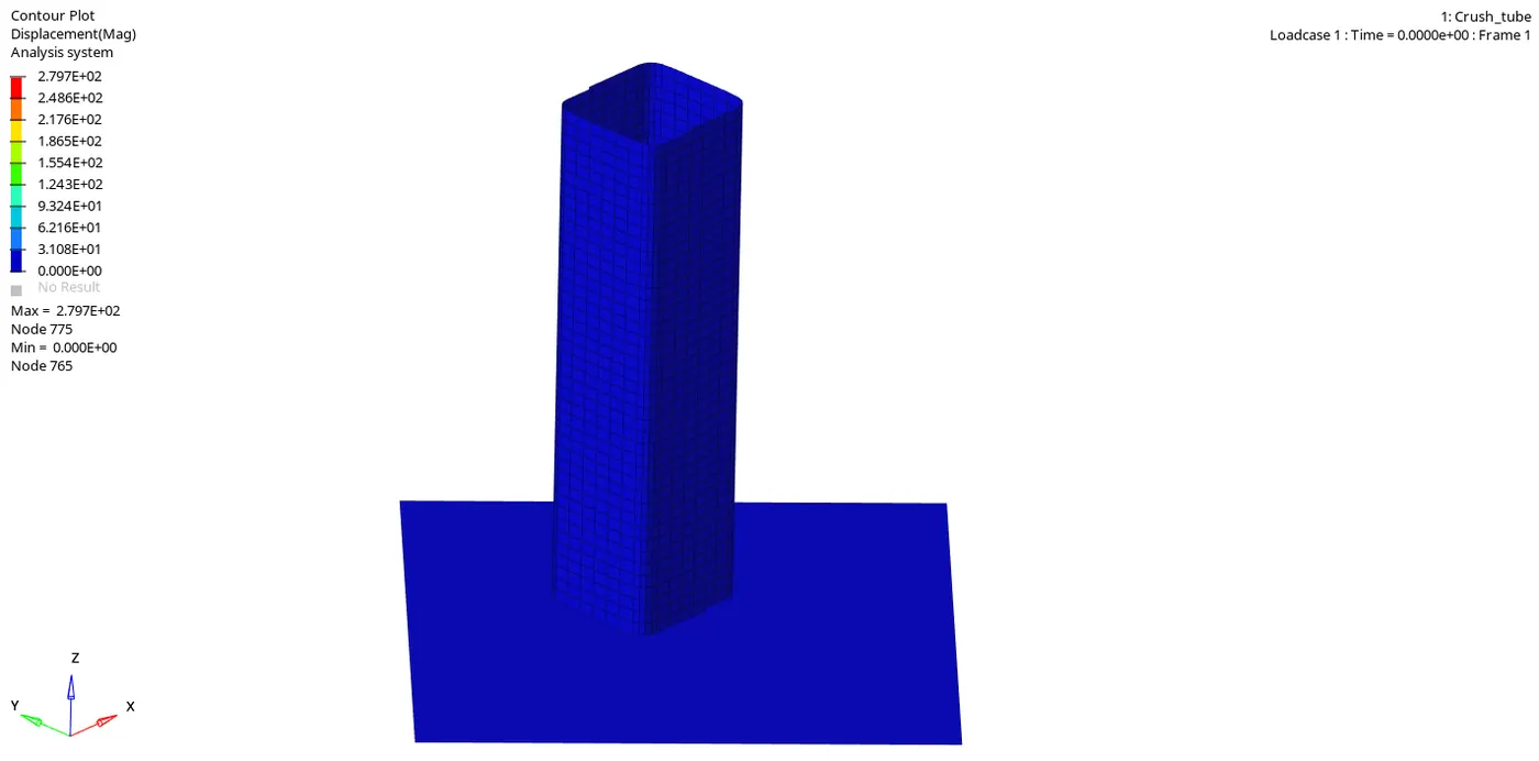
Maximum displacement: 2.797E+02 is at node 775
Minimum displacement: 0.000E+00 is at node 765.
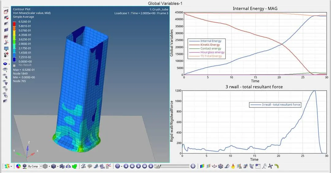
Von-mises Stress Observation:
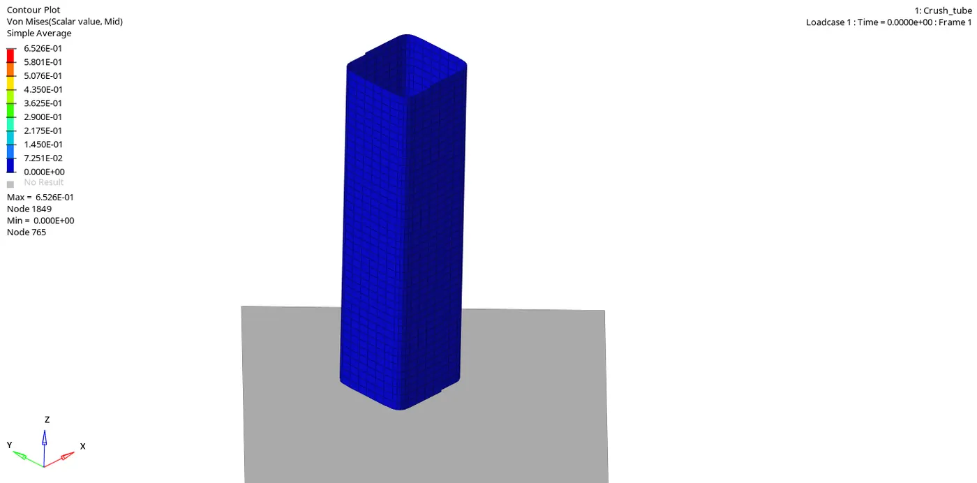
Von-mises stress shows the maximum peak value of 6.526E+01 is at node 1849
Von-mises stress shows the minimum value of 0.00E+00 is at node 765.
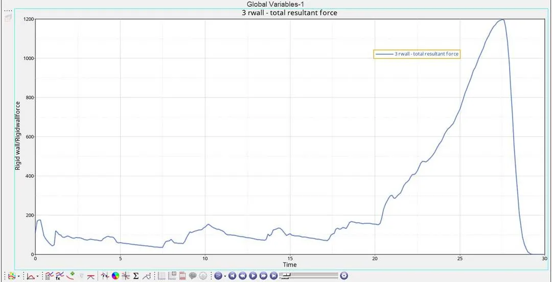
Graph 1: Time versus Internal energy, Kinetic energy, Contact energy, Hourglass energy and Total energy
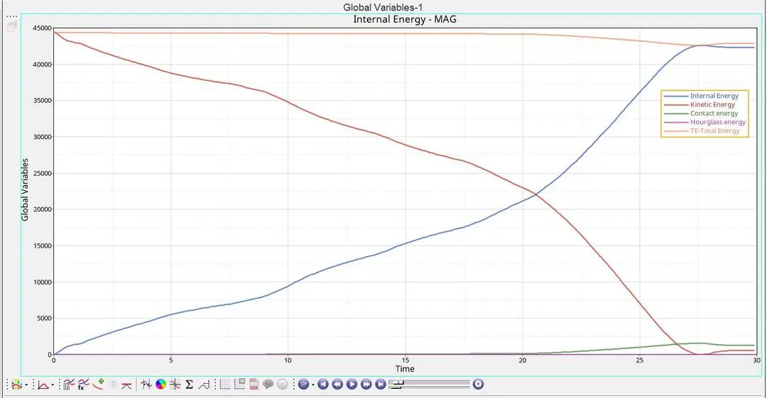
Graph 2: Time versus Rigid wall forces
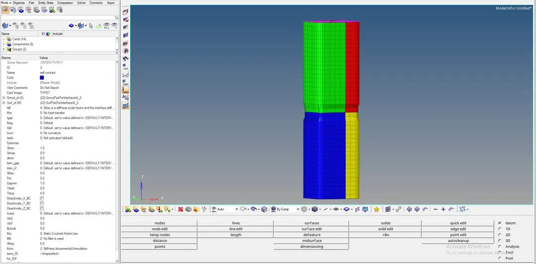
Case 5: Create a new notch in the middle, select the whole section and run
- Import the given crush tube model into hypermesh
- In this case, the notches which were removed during the previous case is created again but in the middle.
- This can be done by using the translate option which is available in the Tools panel.
- Click on the analysis panel in the hypermesh.
- Save the model in the local directory.
- Click the RADIOSS button then run the base simulation.
Open the file "Crush_tube_0001" in notepad to check Energy error, mass error and time elapsed.
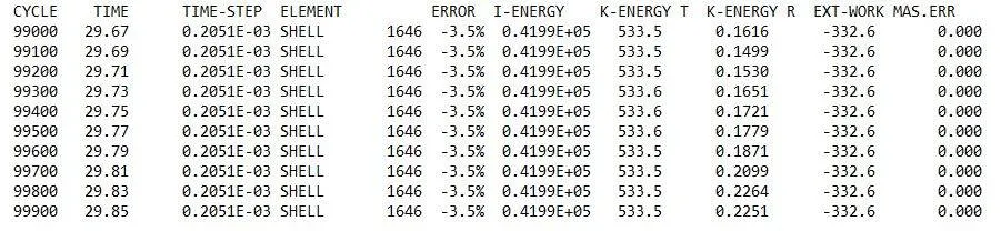
as the energy error is -3.5% which is less than 15% so it is acceptable, also the mass error is found out to be 0.000
Since the energy error is acceptable, the model is moved for further observations by changing the environment to hyper view, then importing the file "Crush_tube.H3d"
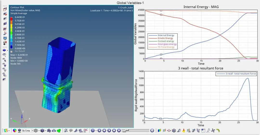
Displacement observation:
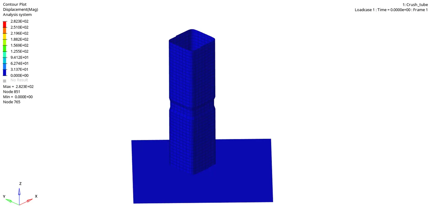
Maximum displacement: 2.823E+02 is at node 851
Minimum displacement: 0.000E+00 is at node 765.
Von-mises Stress Observation:
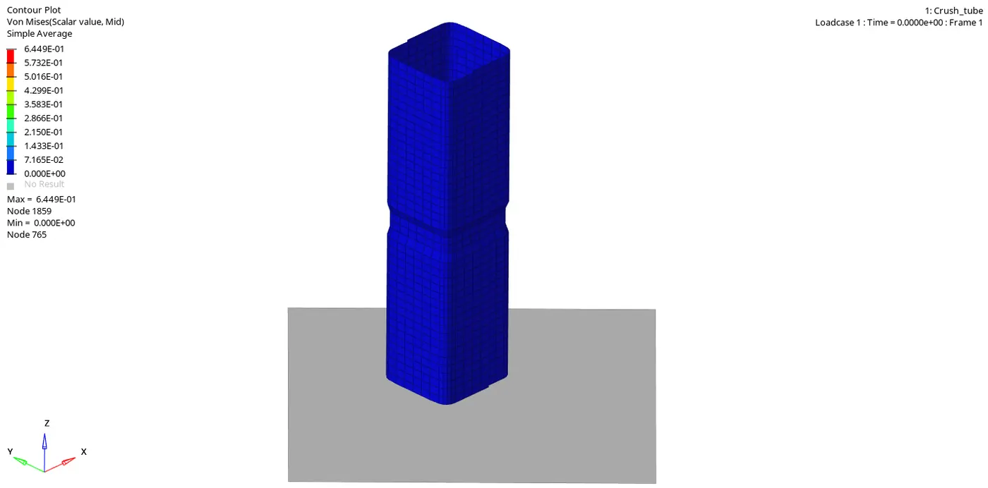
Von-mises stress shows the maximum peak value of 6.449E+01 is at node 1859
Von-mises stress shows the minimum value of 0.00E+00 is at node 765.
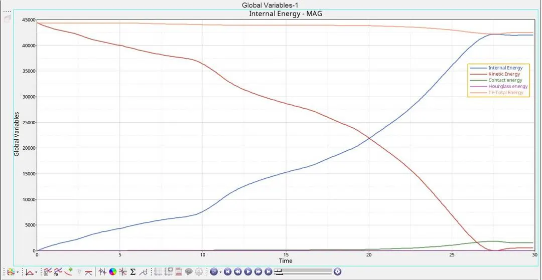
Graph 1: Time versus Internal energy, Kinetic energy, Contact energy, Hourglass energy and Total energy
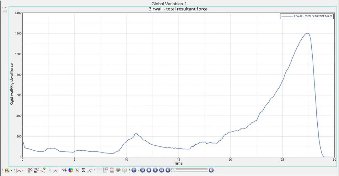
Graph 2: Time versus Rigid wall forces
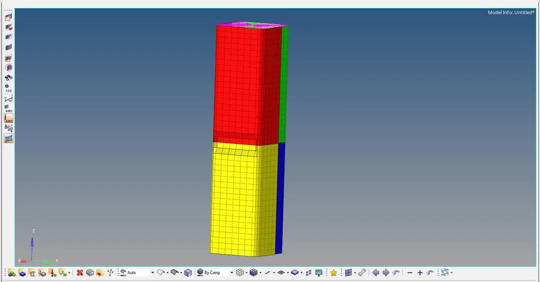
Case 6: Create a new notch with nodes only from opposing two faces and run
- Import the given crush tube model into hypermesh
- In this case, the notches which were removed during the case 4 is created again but only to the opposing two faces.
- This can be done by using the translate option which is available in the Tools panel.
- Click on the analysis panel in the hypermesh.
- Save the model in the local directory.
- Click the RADIOSS button then run the base simulation.
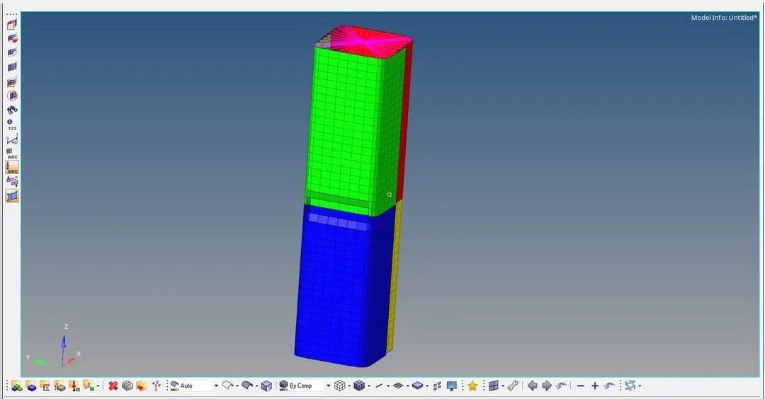
Open the file "Crush_tube_0001" in notepad to check Energy error, mass error and time elapsed.
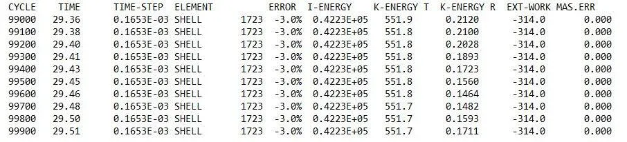
as the energy error is -3.0% which is less than 15% so it is acceptable, also the mass error is found out to be 0.000
Since the energy error is acceptable, the model is moved for further observations by changing the environment to hyper view, then importing the file "Crush_tube.H3d"
Displacement observation:
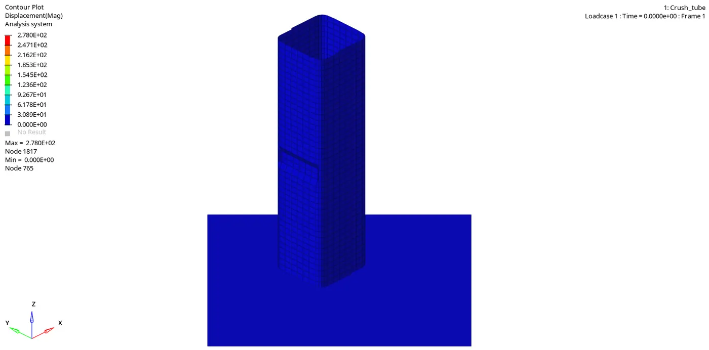
Maximum displacement: 2.780E+02 is at node 1817
Minimum displacement: 0.000E+00 is at node 765.
Von-mises Stress Observation:
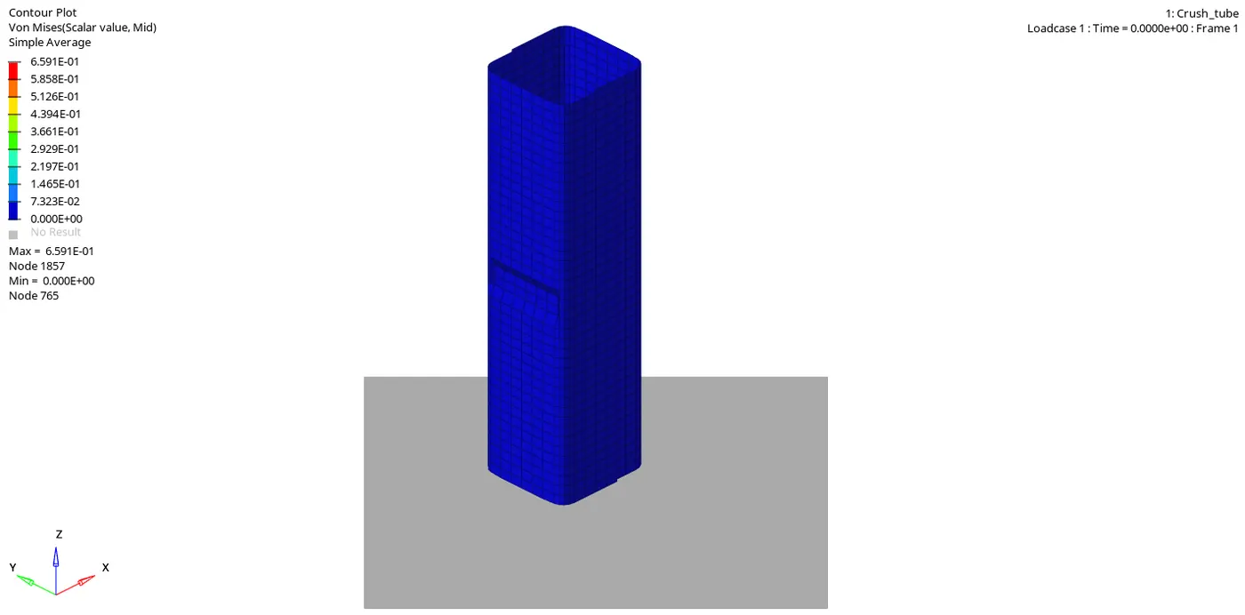
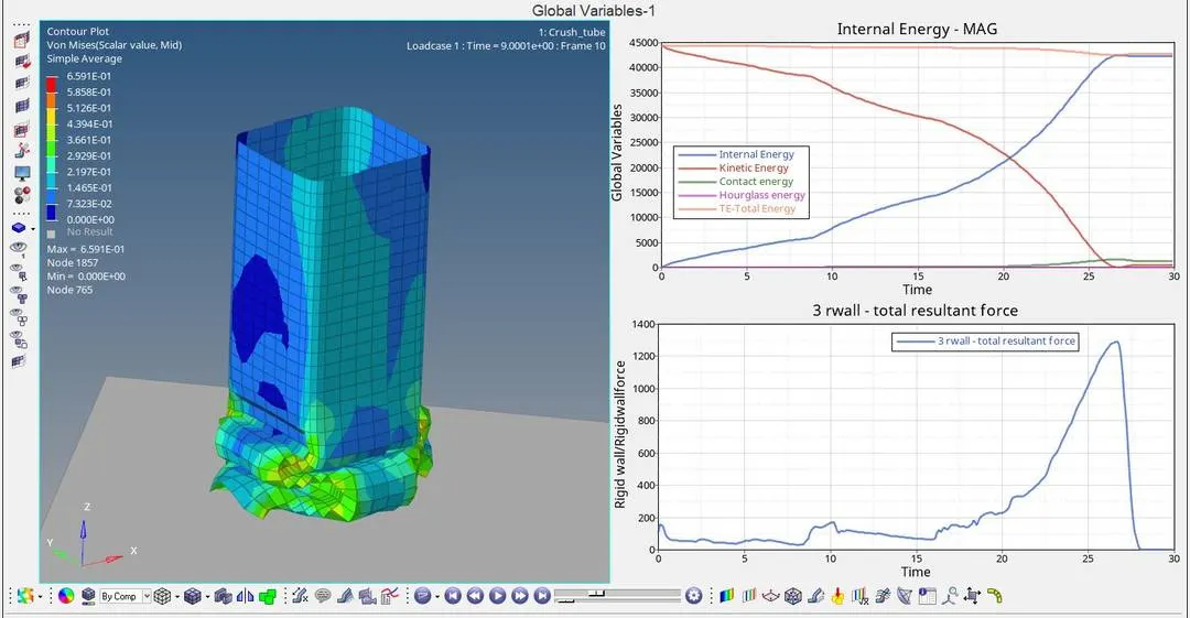
Von-mises stress shows the maximum peak value of 6.591E+01 is at node 1857
Von-mises stress shows the minimum value of 0.00E+00 is at node 765.
Graph 1: Time versus Internal energy, Kinetic energy, Contact energy, Hourglass energy and Total energy
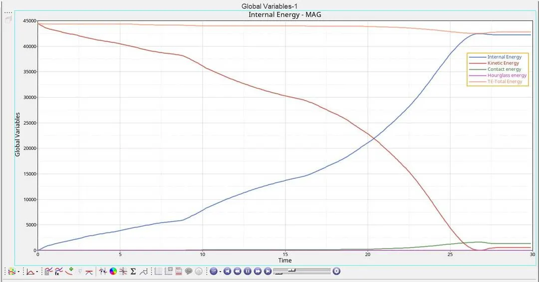
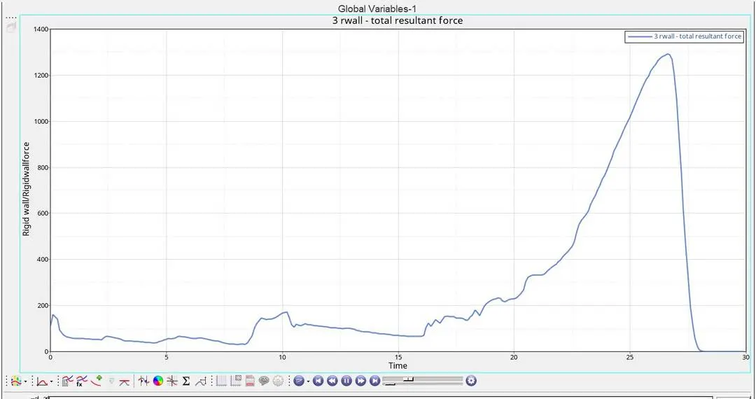
Graph 2: Time versus Rigid wall forces
Comparison of all the cases:
| Type of contact | Number of cycles | Energy error | Mass error | Simulation time | Remarks |
| Case 1: Run the model as it is (TYPE7 contact without the recommended values) | 83496 | -3.8% | 0.000 | 138.70 sec (or) 2min 18sec | Simulation time is manageable compared to the number of cycles it ran, the energy error is slightly higher but also it is acceptable. Nodes undergoing penetration gets deleted hence it Shows realistic results. |
| Case 2: Change the Inacti=6 (TYPE7 contact without the recommended values) | 83490 | -3.8% | 0.000 | 136.88 sec (or) 2min 16sec | Inact value is given as 6 which will give resistive force with respect to time so that the penetration will be removed hence it can be seen that there is no change in energy and force but good accuracy in results is achieved. |
| Case 3: Change to TYPE11 contact | 127877 | -1.6% | 0.000 | 428.63 sec (or) 7min 08sec | Here the number of cycles and simulation time is increased due to the type of contact being edge to edge self impact contact but the energy error is significantly reduced compared to other cases |
| Case 4: Remove both notches and remove the boundary conditions on rigid body | 78444 | -3.0% | 0.000 | 129.65 sec (or) 2min 09sec | Since the notch has been removed it can be noted that the number of cycles is reduced but the energy error is increased compared to the previous case whereas the simulation time is manageable |
| Case 5: Create a new notch in the middle | 100630 | -3.5% | 0.000 | 165.10 sec (or) 2min 45sec | Because of the creation of new notch it the middle shows almost similar results to that of case 1&2 |
| Case 6: Create a new notch with nodes only from opposing two faces | 102846 | -3.0% | 0.000 | 167.87 sec (or) 2miin 47 sec | Here the notches present only on the opposing hence it resists forces from the rigid wall due to which the results obtained is not ideal. |
Comparison of Internal energy and Rigid wall forces on all the cases:
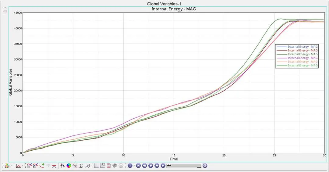
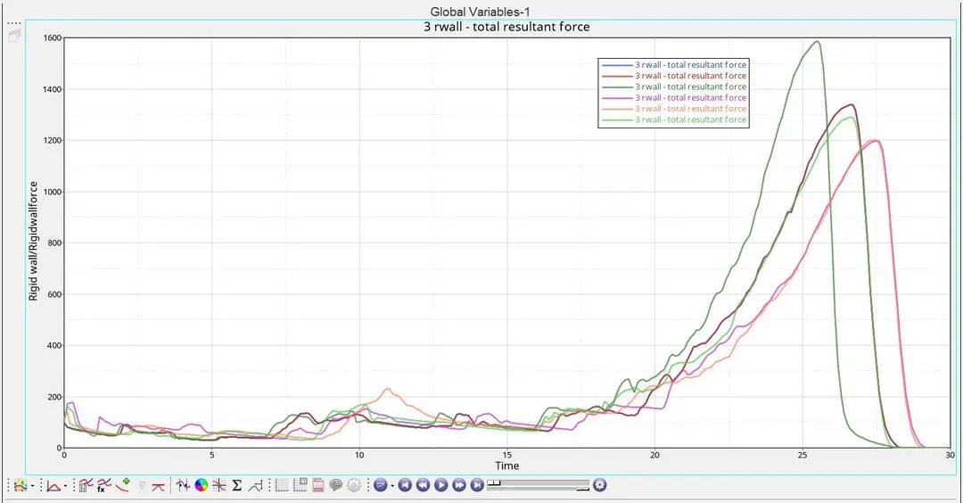
Internal Energies Rigid wall forces
| Type of contact | Peak value of Internal energy | Peak value of Rigid wall forces | Remarks |
| Case 1: Run the model as it is (TYPE7 contact without the recommended values) | 42232.01 J | 1337.90 N | It is noted that the internal energy increases over time whereas the rigid wall forces reach the peak value and begin to descend because of element deletion |
| Case 2: Change the Inacti=6 (TYPE7 contact without the recommended values) | 42273.23 J | 1337.87 N | It shows similar results as compared to case 1 because the resistive force with respect to time so that the penetration will be removed hence it can be seen that there is no change in energy and force |
| Case 3: Change to TYPE11 contact | 42846.74 J | 1587.92 N | Due to the contact being edge to edge the rigid wall forces and Internal energy seems increased significantly |
| Case 4: Remove both notches and remove the boundary conditions on rigid body | 42590.23 J | 1197.90 N | Internal energy produced is decreased because of the removal of notches also it can be noted that there is a delay in time to reach the peak value of both the forces and energy. |
| Case 5: Create a new notch in the middle | 42197.45 J | 1201.36 N | Here the notch is created in the middle which will reduce the generation of Internal energy so the chances of failure get reduced |
| Case 6: Create a new notch with nodes only from opposing two faces | 42449.12 J | 1291.05 N | Because of the presence of notch in the opposing faces Internal energy seems to increases when compared to the previous case also the rigid wall forces get increased because of the resistance from the other faces. |
Conclusion:
The bumper model is meshed and a connection was established in the model using Hypermesh also the given crush tube model is simulated under different contact interfaces and the results have been noted, compared and tabulated to find out the behaviour and importance of Contact interfaces and the impact of notches in a model is also noted.