COMPARISON OF CONTACT WITH DIFFERENT PROPERTIES
AIM:- To establish the connections and compare the run result of different types of contacts
PROCEDURE:-
- We need to import the model into a hyper mesh
- Then we need to clean the geometry
- And perform mesh with a size of 6mm
- Then establish the connection between the surfaces
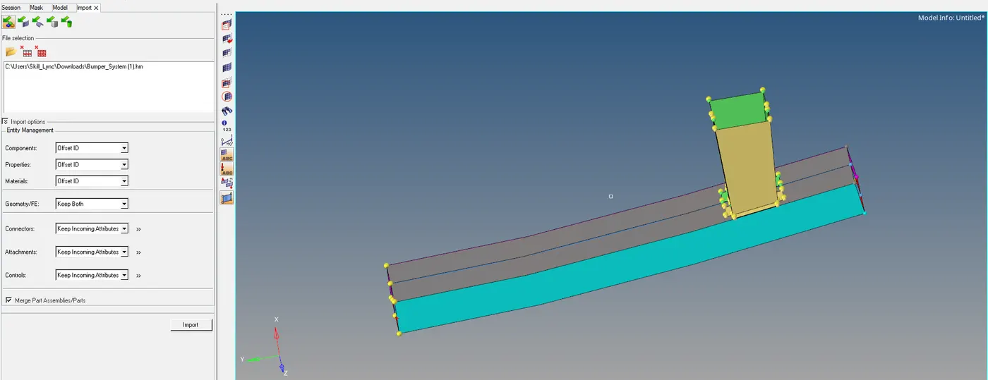
IMPORT THE GEOMETRY
- Go to import and select the file and select import
CLEANING GEOMETRY
- As there are several temporary nodes we need to delete them
- By going to the nodes module and select the temp nodes and select clear all
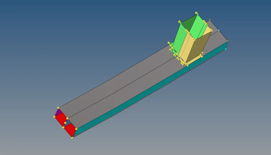
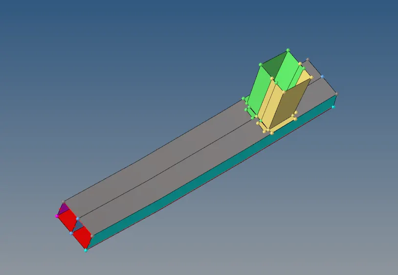
- As there are lines which are not necessary, so we need to delete them
- Go to universal delete and select lines and delete entities
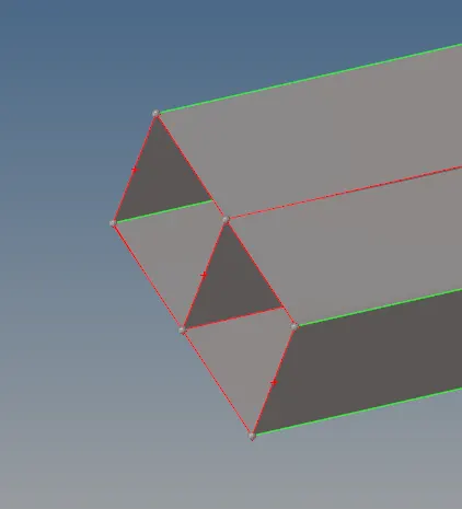
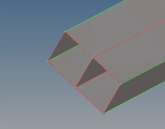
- As we can see more red line on the surfaces we need to connect them by intersecting surfaces
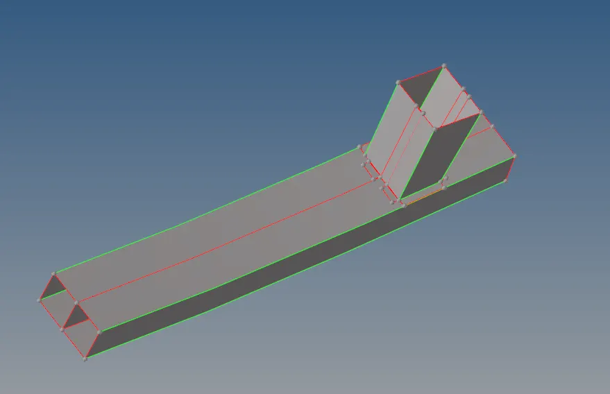
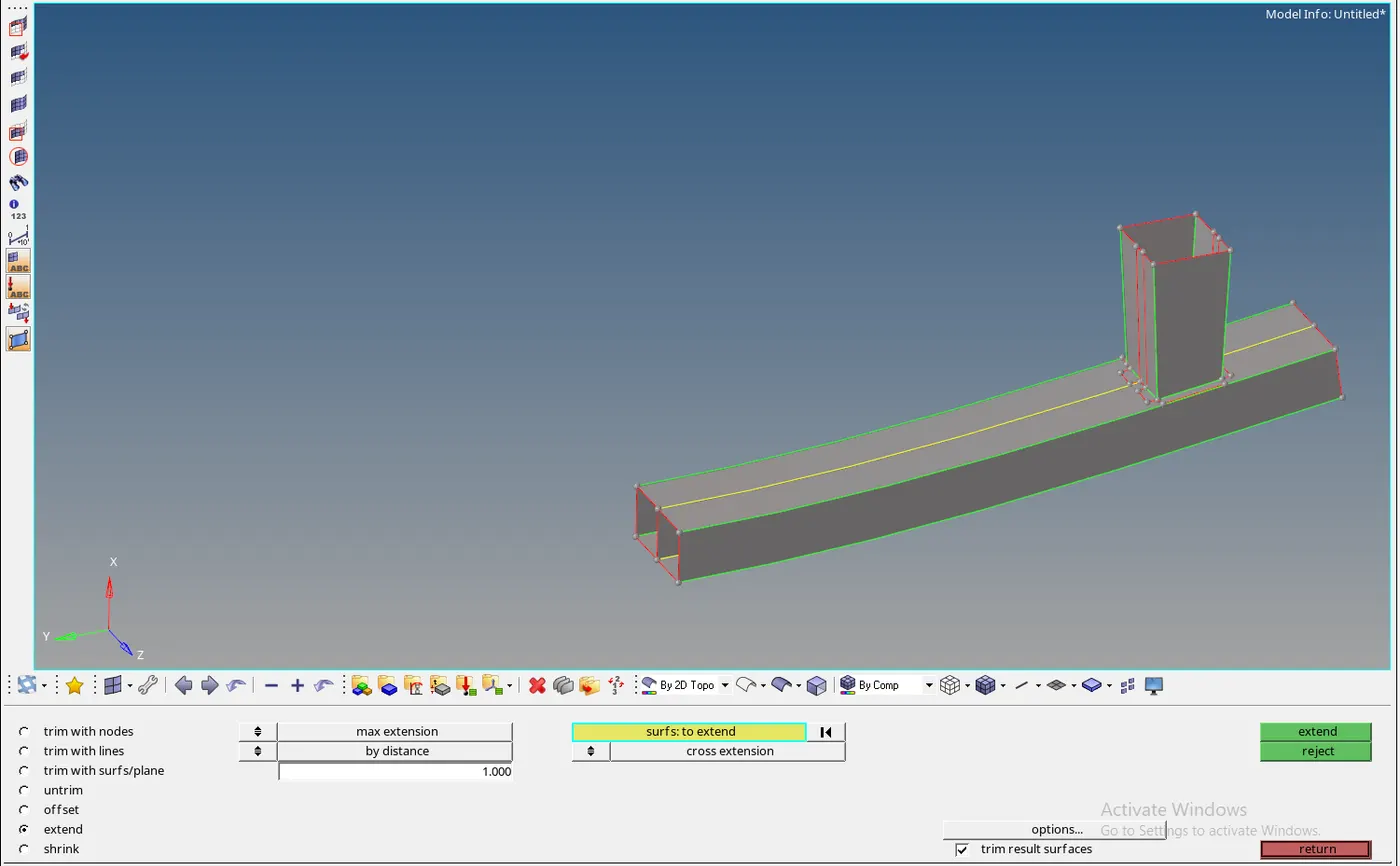
- We need to go the surface edit and extended the surface we can use cross-section (or ) by the surface target
- We shout the more target length to connect
MESHING:-
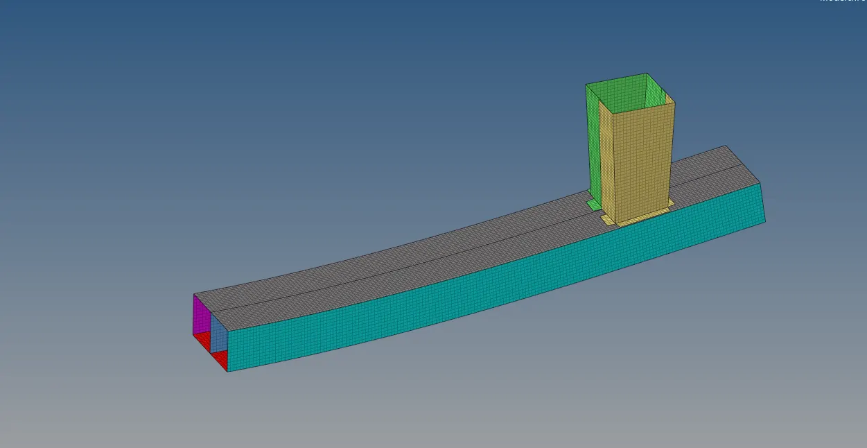
- As these are flat surfaces we can mesh them easily
- Go to auto mesh and mesh it and make no trias occurred at the surfaces
- We can eliminate them by increasing or paralyzing the nodes equally
CONNECTIONS:-
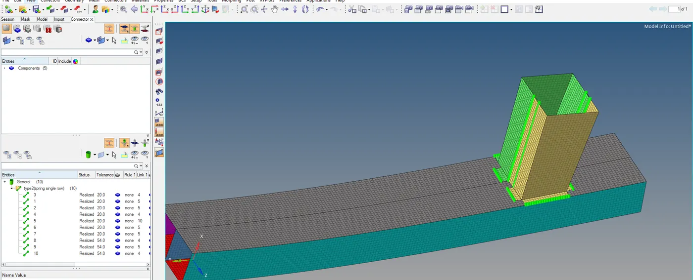
- As the given component is need be connected we are going use the connections
- As the two subparts of offset distance, we are going to give weld connections
- To establish connections we need to 1D menu and select the connectors and select seam weld and change type to spring
- Then we need to select the nodes and then select the components to we welded
- In that tolerance is the space between the components and spacing is nothing but space between the connection that to be created
- To check whether the connections are established are not we need to goto connector in view browse and see that the connections are realized or not
THEORY:-
- As in explicit analysis, we are going to take care of contacts between the surfaces they must calculate with respect to the time
- So there are many interfaces in the radioss to establish a connection
- In any contact, there are two major things which decide the contact with the surfaces they are slave and master
- In which the slave node tries to penetrate into the master node
- There are two types of contact interface algorithm, one is a penalty method and the Lagrange multiplier method
- This penalty method will create a spring for the contact to reduce penetration where the stiffness is calculated by the solver itself
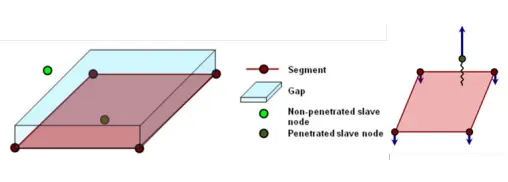
- The penalty method will take a small time step but it might increase the stiffness to stop penetration
- Lagrange method will be a purely physical-based approach no external component like spring will not be created it will solve contact nonlinearity by creating the nonlinear equation
- But it takes larger type step will be taken and it is unable to calculate the friction
- No timestep collapse because it has high interface stiffness
- Different type of interface contacts
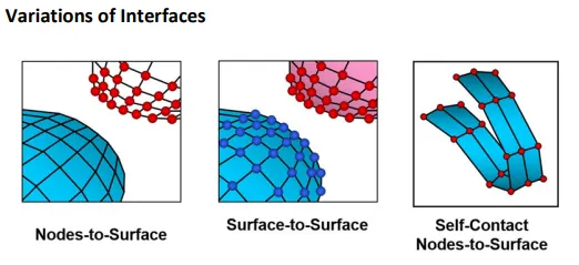
- There are different types of contact algorithms
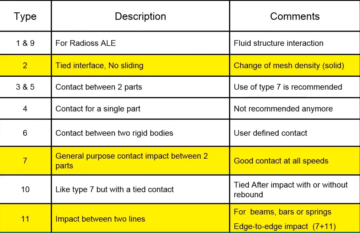
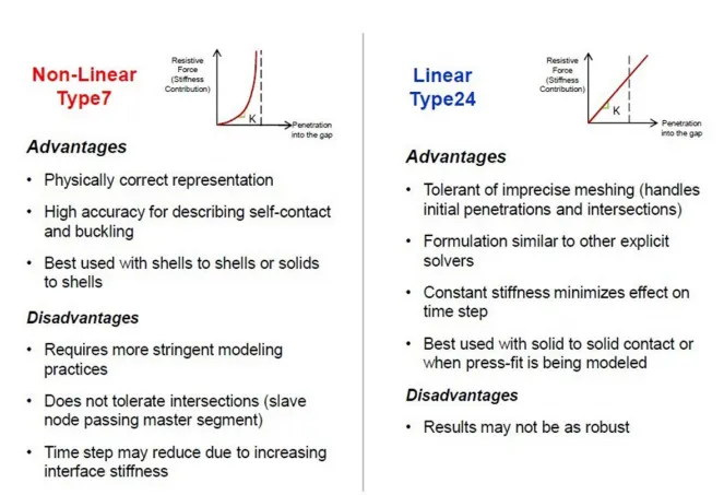
- TYPE7, variable stiffness, node to surface contact
- TYPE11, variable stiffness, edge to edge contact
- TYPE19, a combination of Type 7+11
- TYPE24, linear stiffness, node to surface, and surface to surface contact
- TYPE 7 CONTACT is a multi-stage interference contact
- It has the degree of freedom of transitional and rotation
- It is used general-purpose contact between two parts
- It is auto impact process and also node to surface contact
- It is a nonlinear contact and performs under the penalty method
- In this stiffness is not constant and does not work for edge to edge contact
- It does not work properly if used with a rigid body at high impact speed or a rigid body with a small gap.
- Type 11 is the same as type 7 but it good at the edge to edge contact
- But type 11 uses a complicated algorithm and will slow down the computation
- Type 24 is the combination of type 11+ type 7
- It is a complex algorithm which is used for airbag and crash but it is computationally expensive
- These are following penalty based approach.
- Node-to-surface is the most traditional discretization method for contact interactions and slave node effectively interacts with a projection point on the master surface
- Slave nodes are constrained to do not penetrate the master surface by means of spring
- Rigid surfaces must always act as MASTER surfaces, and Node-based surfaces can act only as SLAVE surfaces.
There are types of contacts
- linear and non-linear contacts
- linear means the penetration will increase by increases with stiffness there will be no change in stiffness
- But in nonlinear material, the stiffness will be variable
PENALTY METHOD

- Here where Vm is the velocity of the MASTER and Vs velocity of the slave node
- The distance between the master and slave is known as the gap
- if the gap is less than the minimum gap then the spring will be created by the solver
- If there is a spring to oppose the moment of slave and master nodes then it must have some property which must be specified

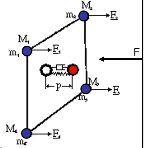
- Ks dependent upon the master surface thickness and its young's modulus
- To activate the contract penetration must be done
- The initial penetration of p must less than 30%
- If penetration is high then ks(contact stiffness) is high which will be transferred to the node
- If the node will have high stiffness it reduces the time step then run will be ended
TYPE 2 (OR) TIED CONTACT
- It is not a sliding contact and will be fixed at the point of application
PROPERTIES OF DIFFERENT INTERFACES
- Ignore:- it is used to delete the non projected slave nodes
- Dsearch:- to find the distance to be projected
- For every contact, these properties shown below must be needed
- Contact gap
- Contact stiffness
- penetration
CONTACT GAP:
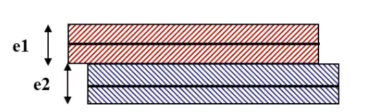
- As we can see that there are two surfaces that parallel to each other they have assigned the thickness of e1 and e2
- Let us consider the red as master and the blue as a slave
- The midline is taken as the midplane of the surface with assigning the thickness
- The distance between the mid surface is the gap
CONTACT STIFFNESS
- Contact stiffness is the stiffness of the spring in the contact
- Depending on the contact stiffness of contact only the penetration can be reduced
- Penetration can be reduced in two ways one was to increase the stiffness or to remove the nodes that undergone intersection
PENETRATION
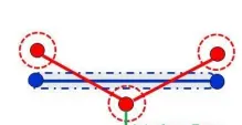
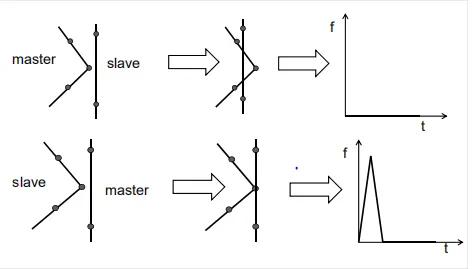
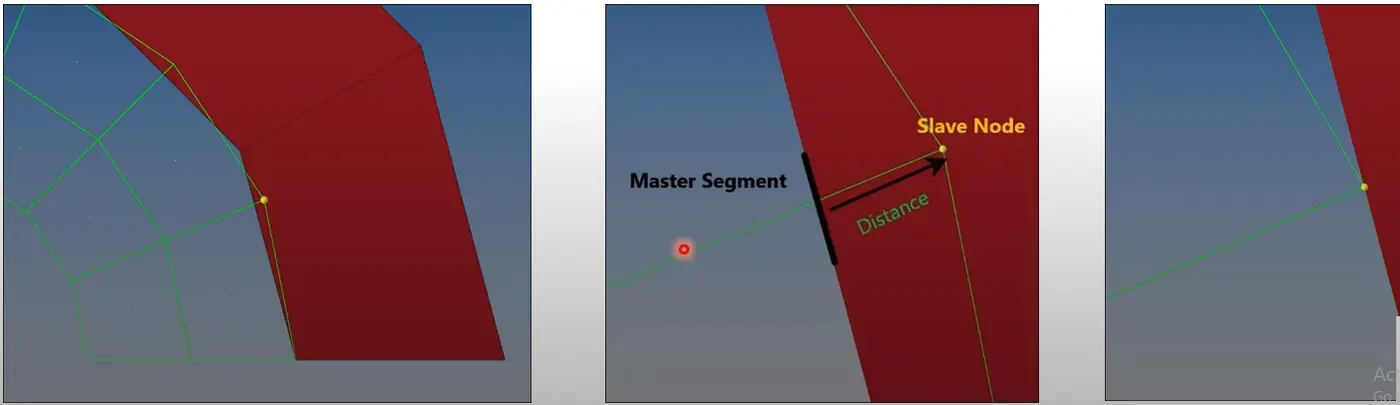
- Penetration is nothing but the slave node that crossing the boundaries of the master surface
- To search penetration there are two techniques one was old node based search and bucket sort search
- As we can see from that graph due to penetration the result is produced, so we need to delete the penetration
- As you can see that below figure the example of penetration at initial that is called initial penetration should be less than 30% of initial gap
Important Interface Parameters
Igap Determines how the size of the gap is calculated
Gapmin Minimum gap for activation of the interface
Inacti Action to take if initial penetrations exist
Istf Affects how the stiffness of the interface is calculated
Iform Friction formulation
Stmin Minimum stiffness to use in the interface
Idel Update For Deleted Elements Due To Failure
PREFERENCE GIVE TO THIS PROPERTIES
- Igap is used to calculate the gap between master and the slave
- In those there are 3 options Igap=0,1,2,3

- If Igap is zero then it will consider the gap minimum value
- If Gapmin is not defined or set to zero, then Gapmin = min (tm, lmin/2) where:
• tm is the average thickness of master shell elements
• lmin is the smallest side length of all master segments (shell or brick) - Gapmin = lmin/10 is taken for brick elements
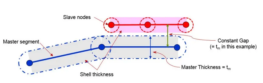
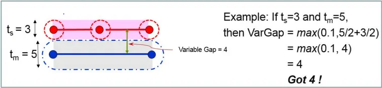
- If Igap =1(variable gap )

- formula to calculate the gap if Igap =1 then it would take Gap = max [Gapmin, (gs + gm)]
gm: master element gap
gs: slave node gap
gm = tm/2, where tm is the thickness of master shell – or zero for master brick
elements
gs = ts/2, where ts is the largest thickness of shell connected to slave node – or
zero if a slave node not connected to any element or only connected to the brick
or springs
- If Gapmin is not specified or set to zero, you can get unexpected results,if specified the result will accurate
- Gapmin = tm, (if Gapmin is not specified and tm < lmin/2)
- If Igap =2

Gap = max {Gapmin, min [Fscalegap*(gs + gm), Gapmax]}
Fscale the gap scale >1.0(0.8/0.6)
- In this, we need to specify scale facto
- If there is an initial penetration when the gap value is larger than the mesh size then igap =3 is considered
Inacti
- Action with respect to the initial penetration
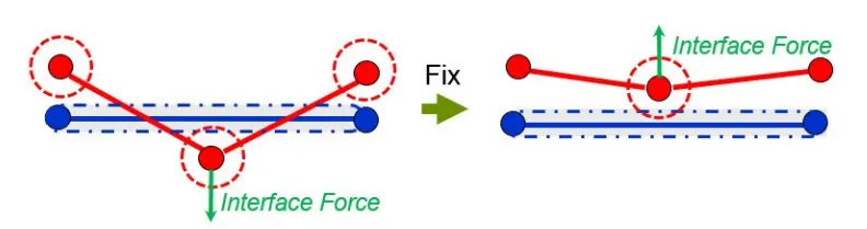
- if inact =1 is used when the intersection is there and it deletes the nodes
- If inact=6 is used to reflect back the nodes from penetration with respective time by applying the force
Istf
- It is nothing but the stiffness of the spring when penetration occurred
- The stiffness will be calculated from the master and slave material stiffness
- As we need to have a minimum stiffness value we are going to consider the Istif value as 4
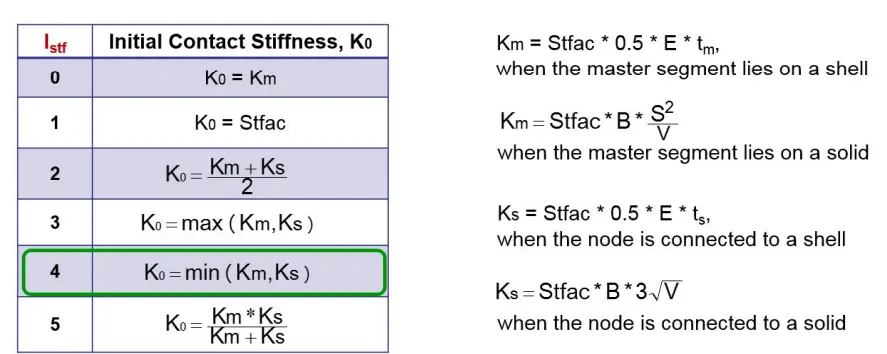
Stfac =Stiffness scale factor applied to the master side of the interface
final stiffness calculation

stmin = Minimum stiffness
stmax = Maximum stiffness
Iform
- calculation of friction whether the friction formulation must be calculated at total then set as i
- For incremental calculation keep it as 2
Idel
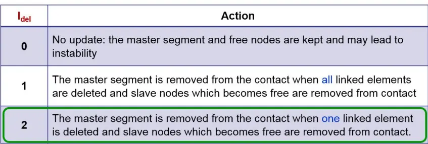
- Deleting the nodes when elements are failed select it as 2
Stmin
- To reduce the soft contact we use the minimum value as 1000n/mm^2
CONTACT ENERGY
k= interface stiffness
g = contact gap thickness
p= penetration into the contact gap
Ln is the natural logarithm.
CASE 1:-Run the crash tube model as it is.
- As of now, we need to import the model and run as it is
- These are the initial condition give for the body
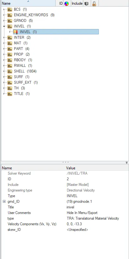
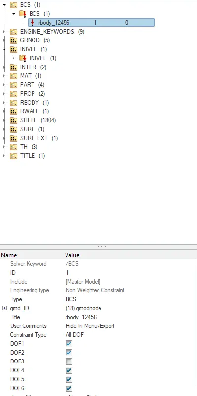
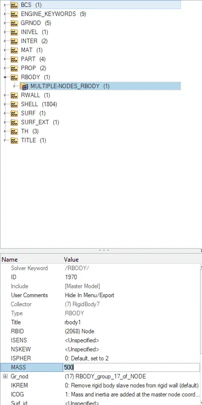
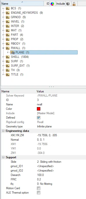
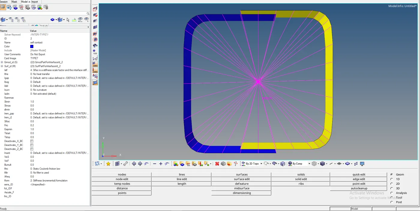
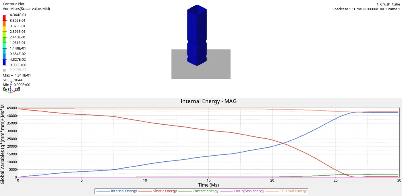
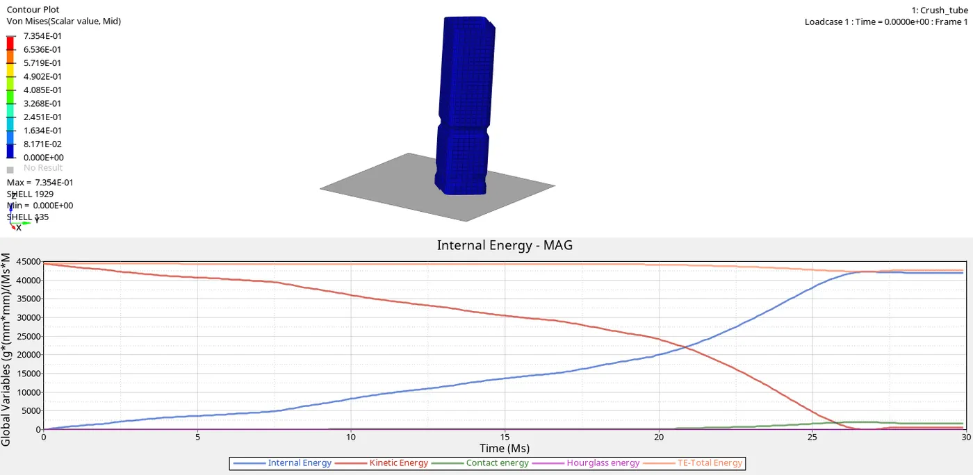
- As we had given the material as elastic and contact between them is type 7
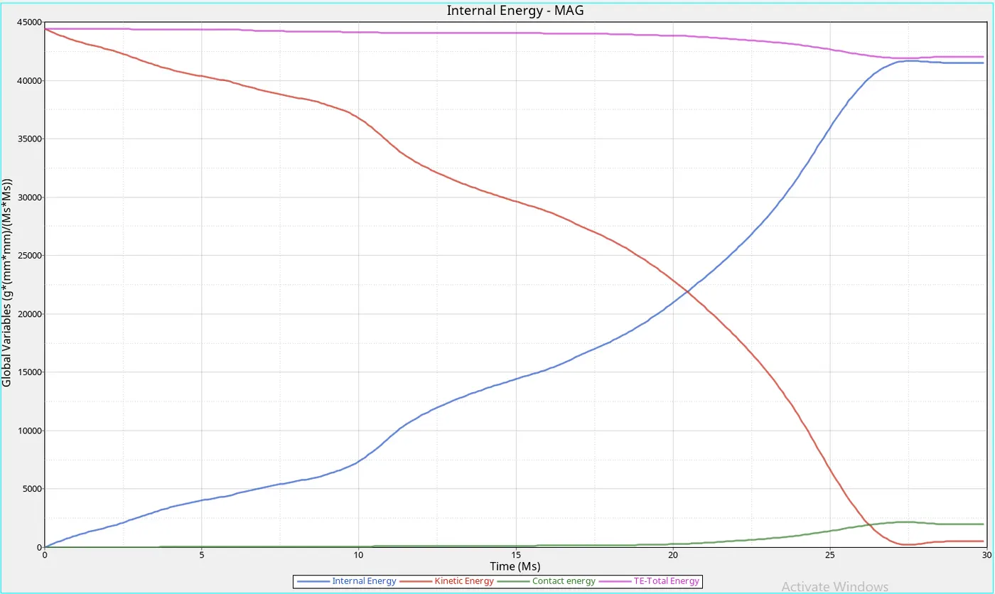
- We can see that as the kinetic energy decreases with an increase in strain energy (Internal energy)
- As we can see that the contact energy is raising at 20ms and after 27ms it is neutral
- The raise in contact, internal energy caused due to the bounce-back of the component after complete contact of the component to the rigid wall
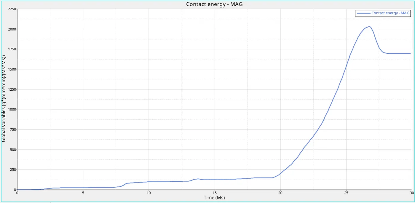
- The maximum contact energy is obtained at 2100mJ
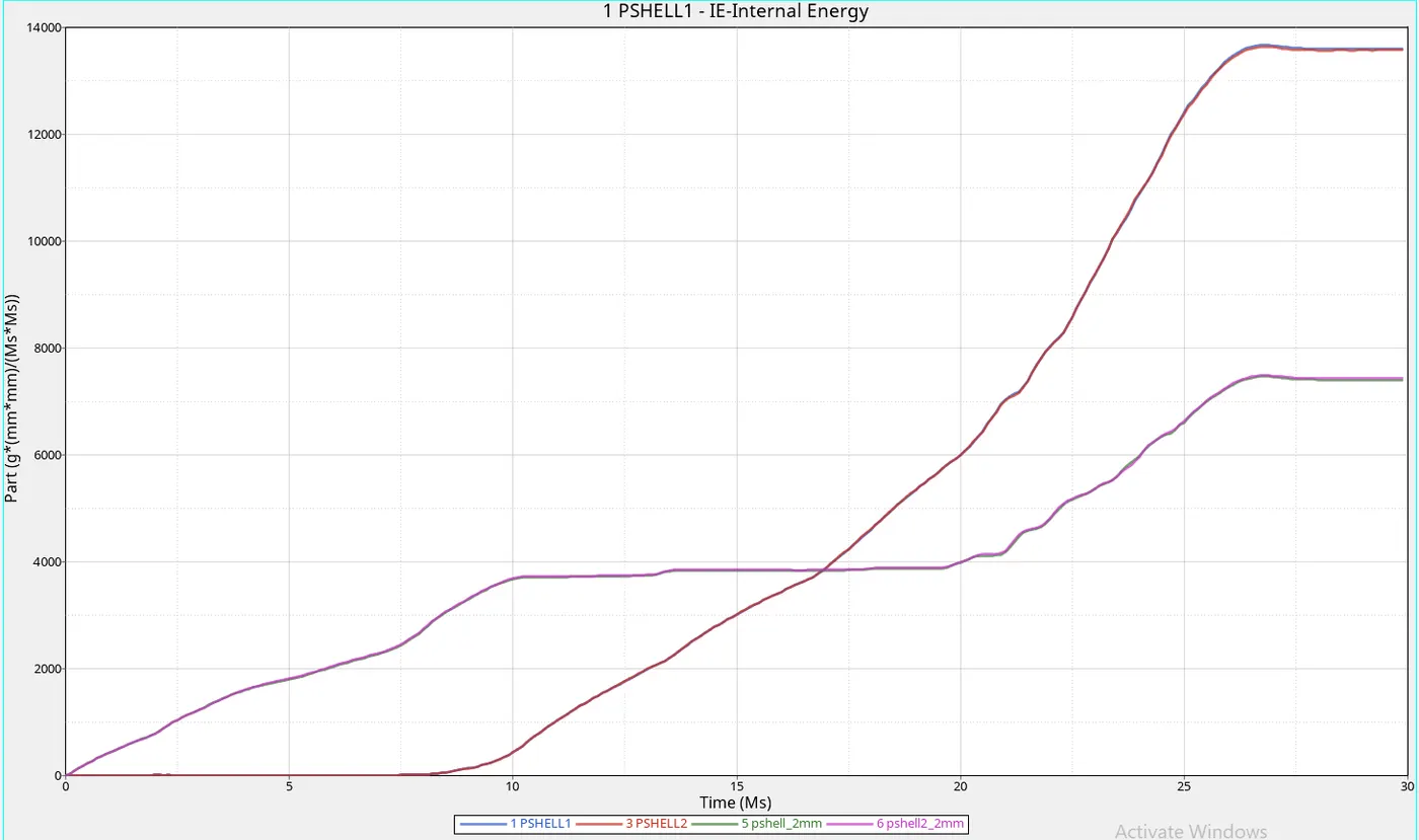
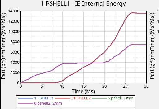
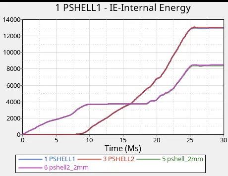
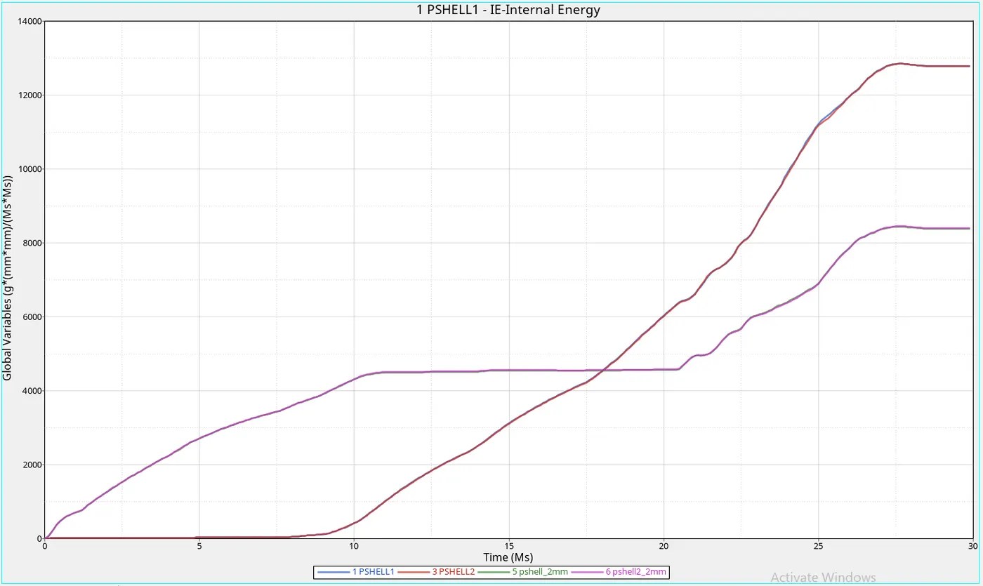
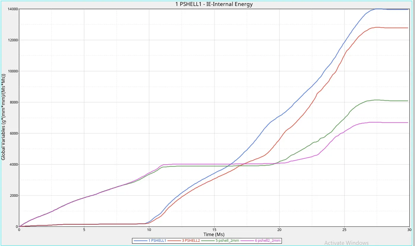
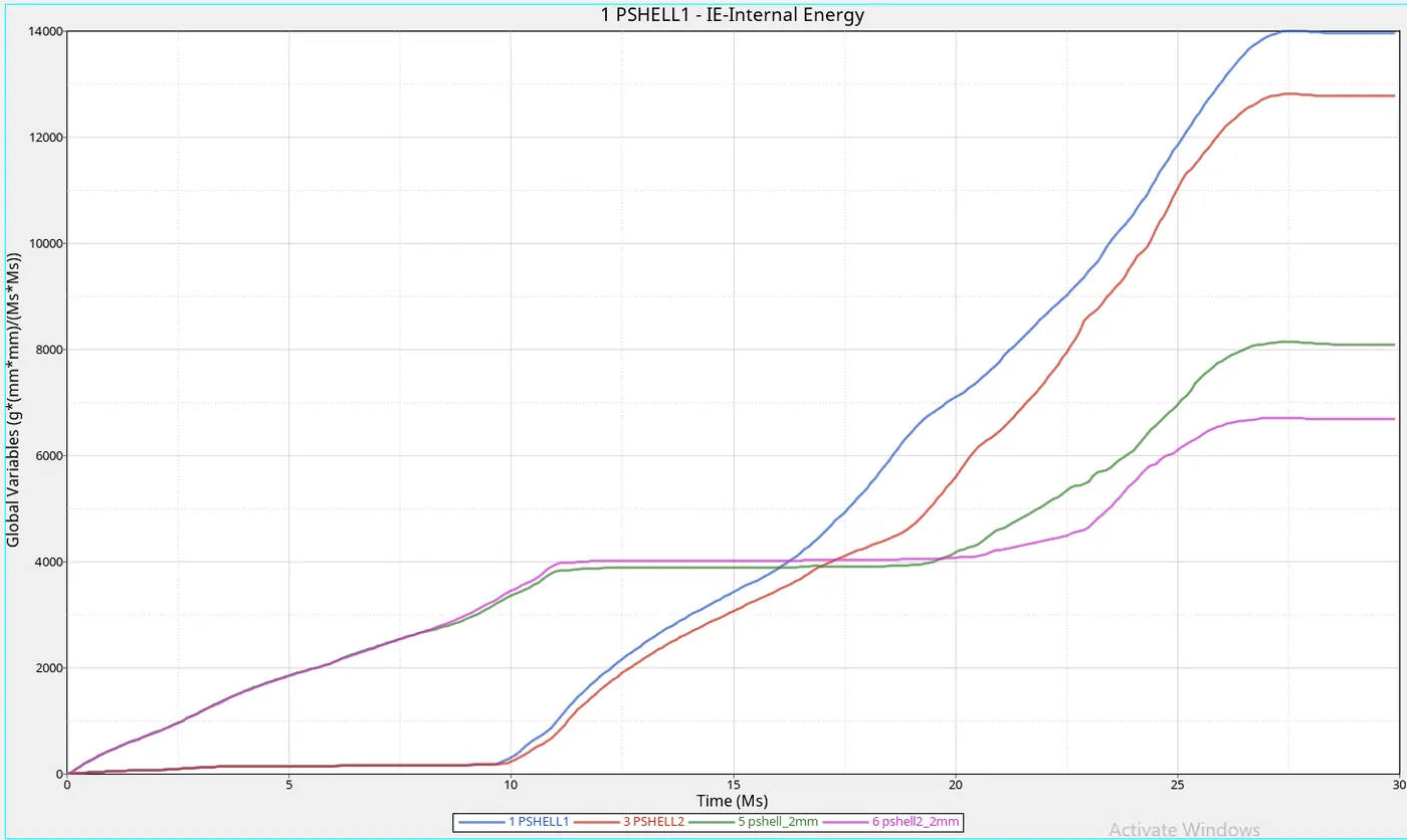
- As this is the internal energy generated at each sub-component as we can get to know that easily the component which undergoes impact the component will have high internal energy and other will constant internal energy unless the impact occurs.
- The pshell1 and pshell2 internal energy is increased after 5.8ms, up to 5.8ms the application of force is taken and it is able to restrict the force after that we can seen sudden increase in internal energy
- But in the other two components, we can see that the internal energy is increasing from the starting because of the high impact load acting instantaneously
- Maximum Internal energy 1,2 = 6500mJ
- Maximum Internal energy 3,4= 13500mJ
CYCLE TIME TIME-STEP ELEMENT ERROR I-ENERGY K-ENERGY T K-ENERGY R EXT-WORK MAS.ERR
83300 29.95 0.2455E-03 SHELL 1927 -3.8% 0.4202E+05 592.6 0.2732 -105.2 0.000
83400 29.98 0.2455E-03 SHELL 1927 -3.8% 0.4202E+05 592.6 0.2780 -105.2 0.000
STARTER+ENGINE RUNTIME = 350.21s (00:05:50)
MAXIMUM TIME STEP. . . . . . . . . . . . . . . . 0.1000000E+31
TOTAL NUMBER OF CYCLES : 83496
- As we can see that the error percentage -3.8% it is acceptable and hourglass energy is constant
CASE 2:-Change the Inacti=6 and run.
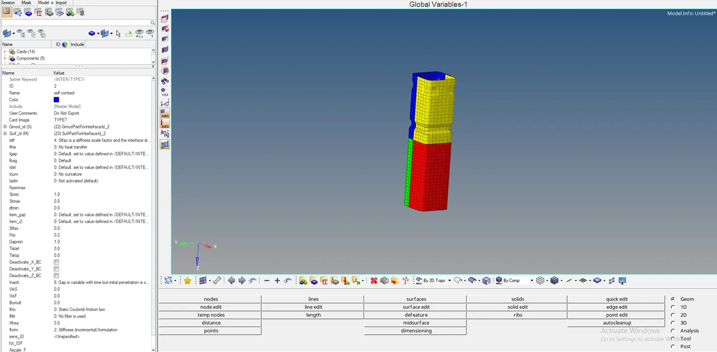
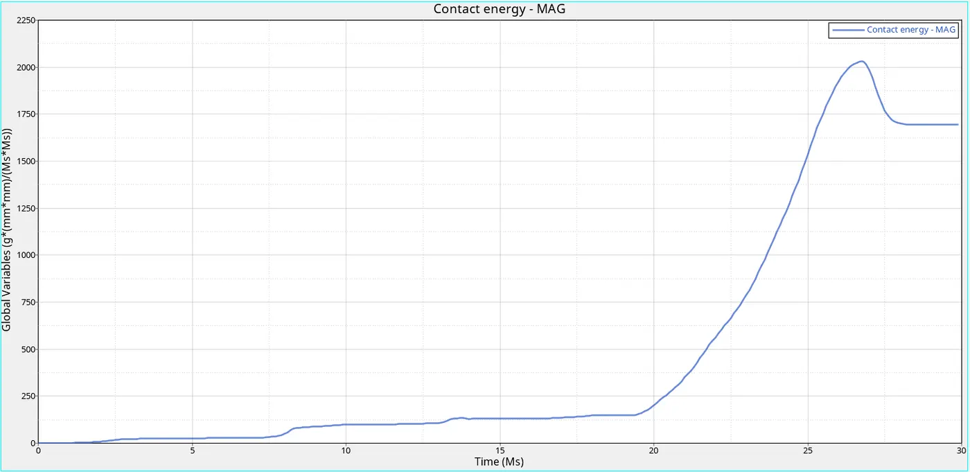
- As component has contact energy as 2100mJ
CYCLE TIME TIME-STEP ELEMENT ERROR I-ENERGY K-ENERGY T K-ENERGY R EXT-WORK MAS.ERR
83300 29.95 0.2455E-03 SHELL 1927 -3.8% 0.4202E+05 592.6 0.2732 -105.2 0.000
83400 29.98 0.2455E-03 SHELL 1927 -3.8% 0.4202E+05 592.6 0.2780 -105.2 0.000
TOTAL NUMBER OF CYCLES : 83496
STARTER+ENGINE RUNTIME = 371.88s (00:06:11)
MAXIMUM TIME STEP. . . . . . . . . . . . . . . . 0.1000000E+31
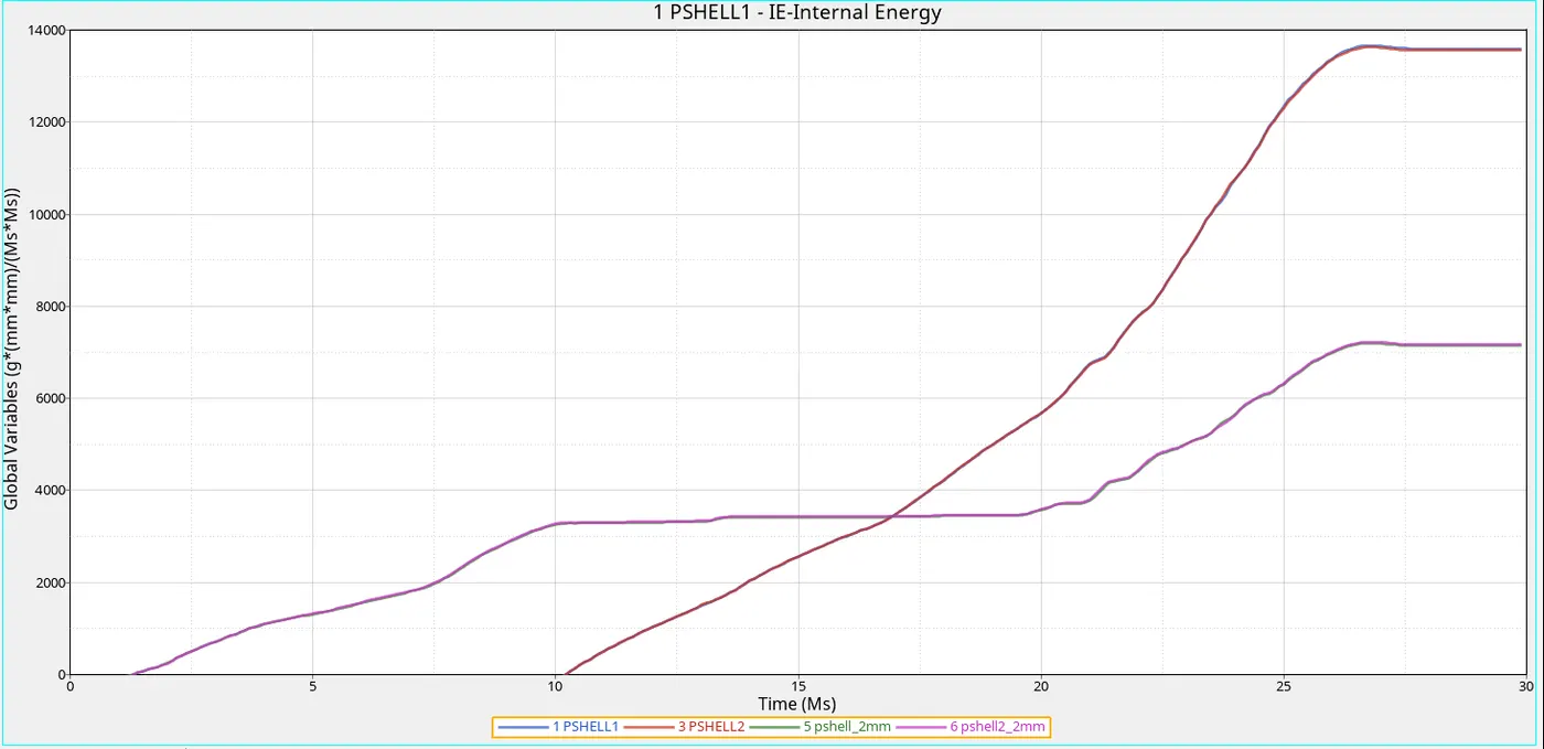
- As this is the internal energy generated at each sub-component as we can get to know that easily the component which undergoes impact the component will have high internal energy and other will constant internal energy unless the impact occurs.
- The pshell1 and pshell2 internal energy is increased after 5.8ms, up to 5.8ms the application of force is taken and it is able to restrict the force after that we can seen sudden increase in internal energy
- But in the other two components, we can see that the internal energy is increasing from the starting because of the high impact load acting instantaneously
- Maximum Internal energy 1,2 = 6500mJ
- Maximum Internal energy 3,4= 13500mJ
CASE 3:-Create the type 11 contact and run.
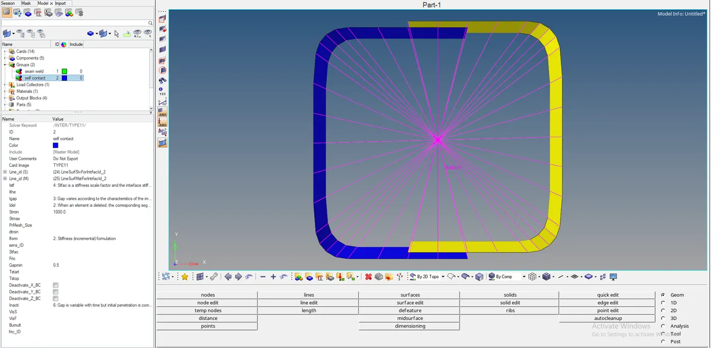
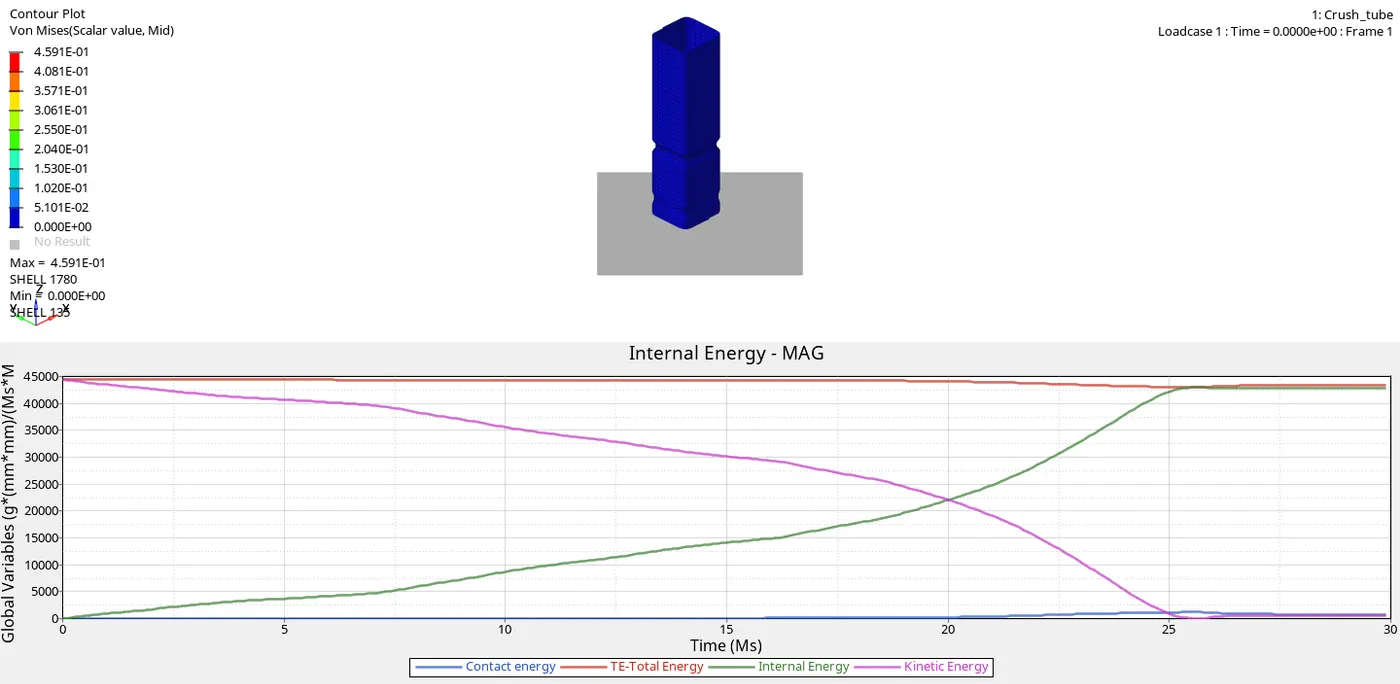
- As we changed contact from type 7 to type 11 which uses the complicated algorithm which take more no of cycles
- And a high amount of energy required for this type of contact we see that the Internal energy is occurring at 42000mJ
- But we can see that contact energy low compared to other cases it is about 1200mJ
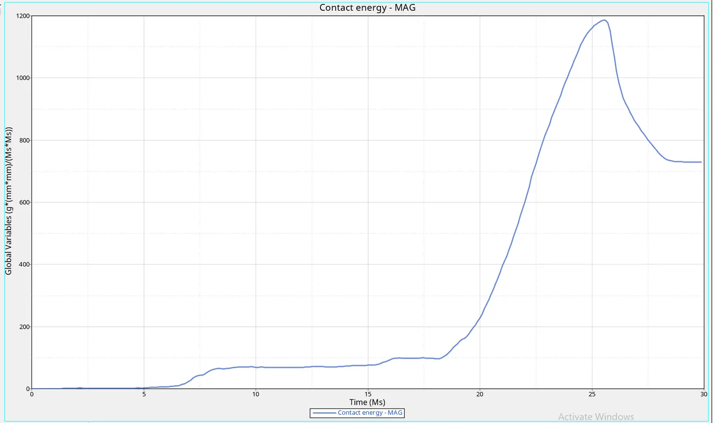
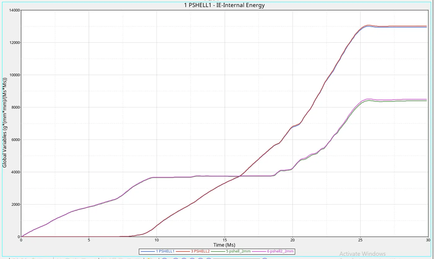
- As we can see that there is small change internal energy between part shell1 and shell2 it is because of type 11 contact it will take care about edge to edge contact
- The contact is giving the less internal energy compared to the other cases because the energy required for penetration is less
MAXIMUM TIME STEP. . . . . . . . . . . . . . . . 0.1000000E+31
CYCLE TIME TIME-STEP ELEMENT ERROR I-ENERGY K-ENERGY T K-ENERGY R EXT-WORK MAS.ERR
127700 29.96 0.2305E-03 NODE 1060 -1.6% 0.4285E+05 610.3 0.4795 -214.7 0.000
127800 29.98 0.2305E-03 NODE 1060 -1.6% 0.4285E+05 610.3 0.4893 -214.7 0.000
TOTAL NUMBER OF CYCLES : 127877
STARTER+ENGINE RUNTIME = 946.60s (00:15:46)
CASE 1 VS CASE 2
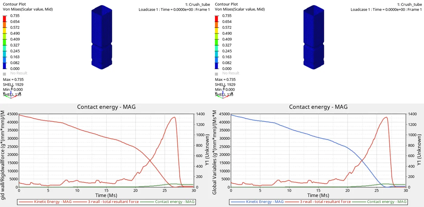
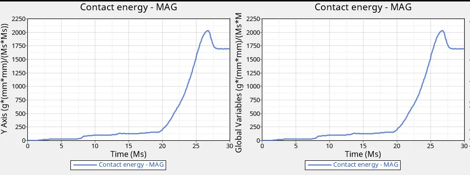
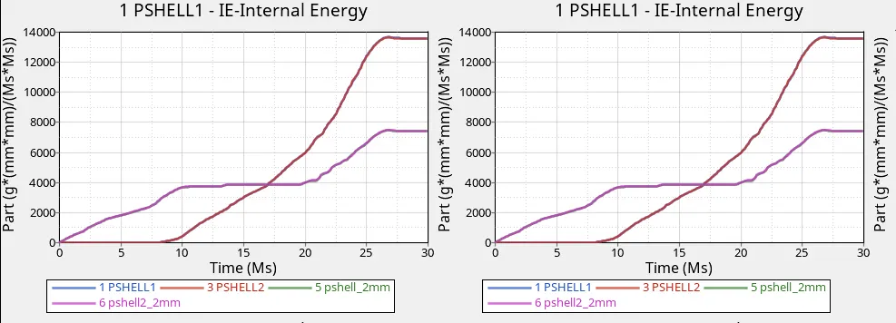
- Comparing case 1 and case2 I had noticed that there is no change in the energy and force
- As intact 6 and inact 0 does the same work to reduce penetration
- But intact 6 will give good accuracy compared to inact 0 because it works on the principle of the vicious method to apply resistive force with respect to the time the penetration will be removed
- But whereas inact o will delete the nodes which undergo penetration so that there is no chance of penetration
- Becuse of that we are unable to find the difference but the difference in a cycle that increased the accuracy of the component in inact 6
CASE1 VS CASE 3
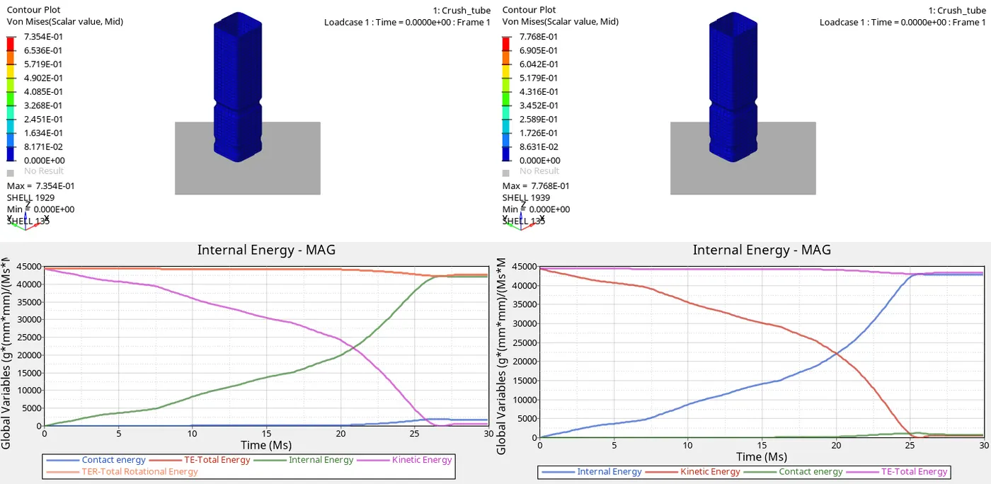
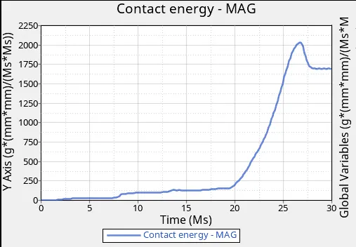
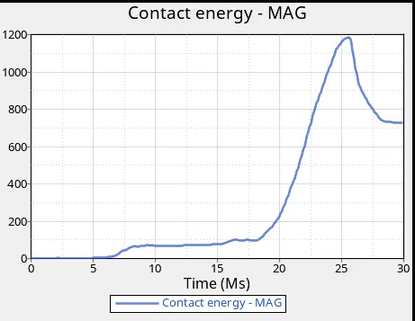
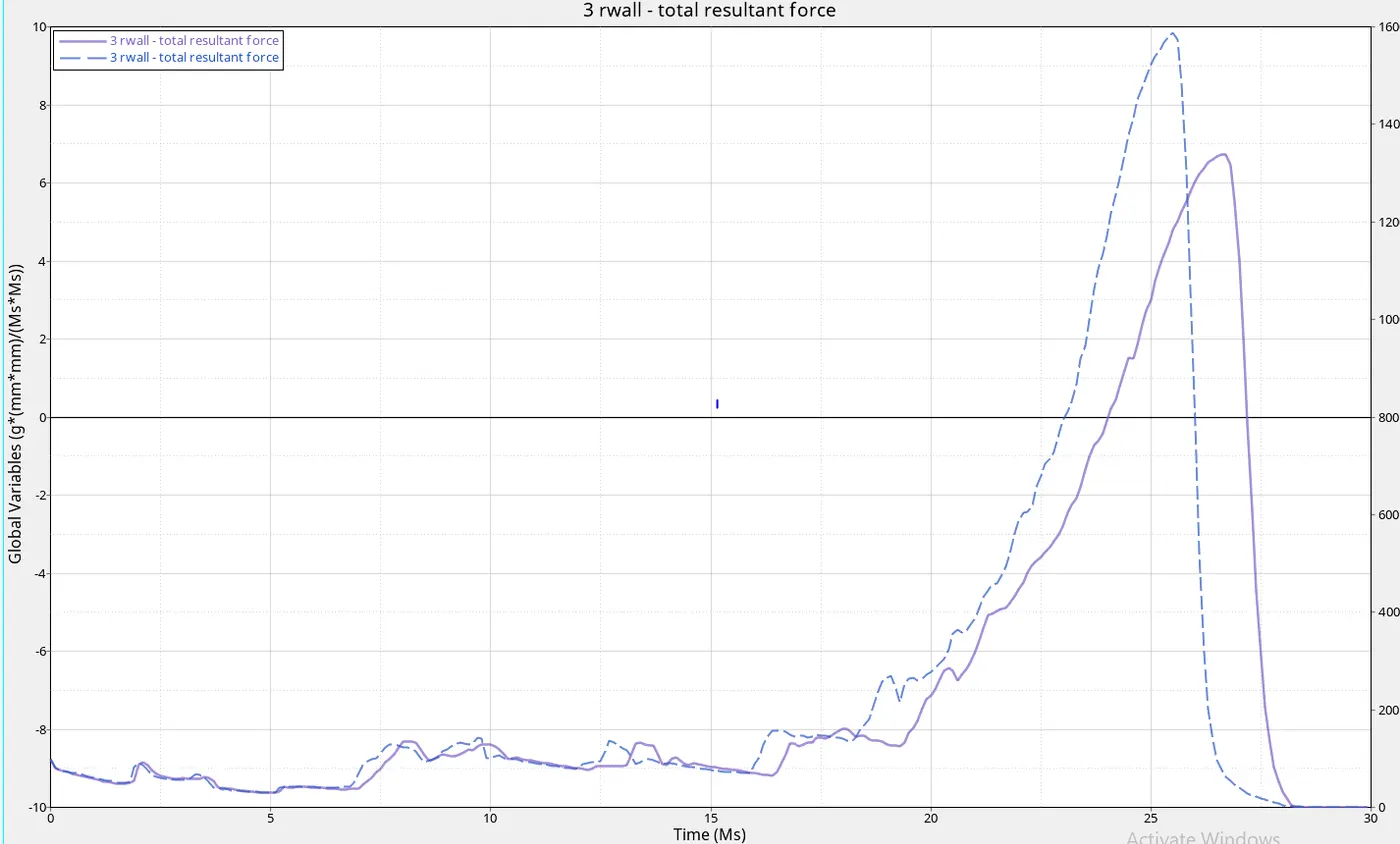
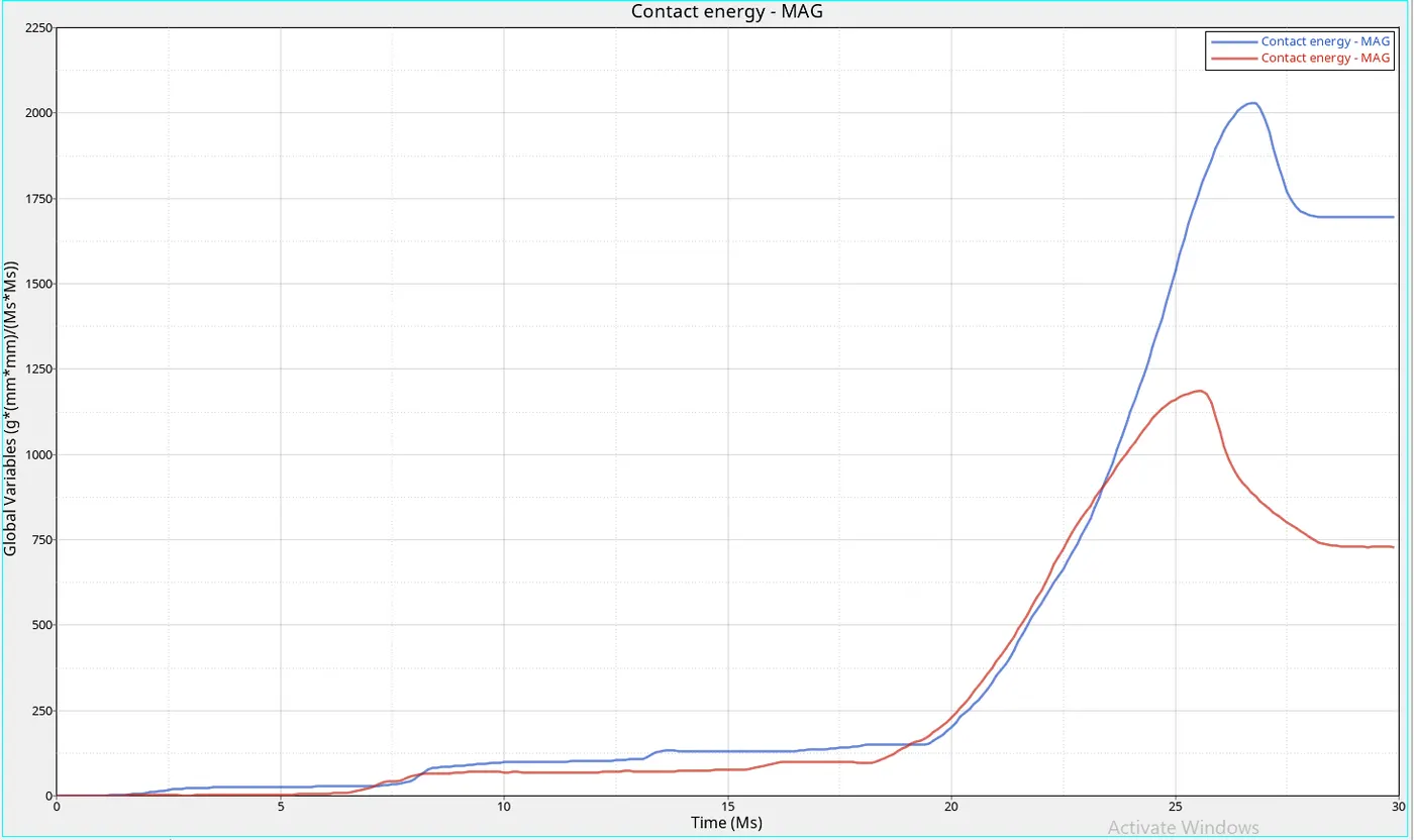
- The major difference in case 1 vs case 3 is the rigid wall forces and contact energy
- As of now for type 7 contact energy is high because the penetration is low
- But as the force obtained by the rigid wall is low for type 7 contact due to proper distribution of forces are been undergone
- We can see that the contact energy is been started for type 7 is started initially but type 11 contact is been started after 5ms so that the type 7 will increase the accuracy of contact with respect to the results
CASE 4:-Remove both notches and remove boundary condition on rigid body node then run
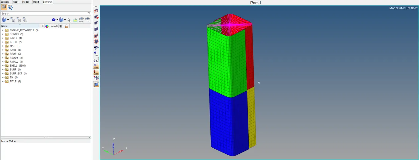
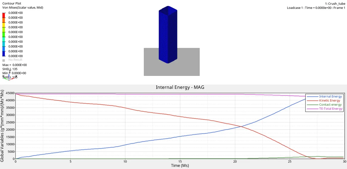
- In this, we could find the absence of notch and boundary condition like no mass added to the body and also rigid support is deleted at other end
- So that there will gradual increases in the I.E and decrease K.E at less span of time
- The resistive force will less to object the velocity
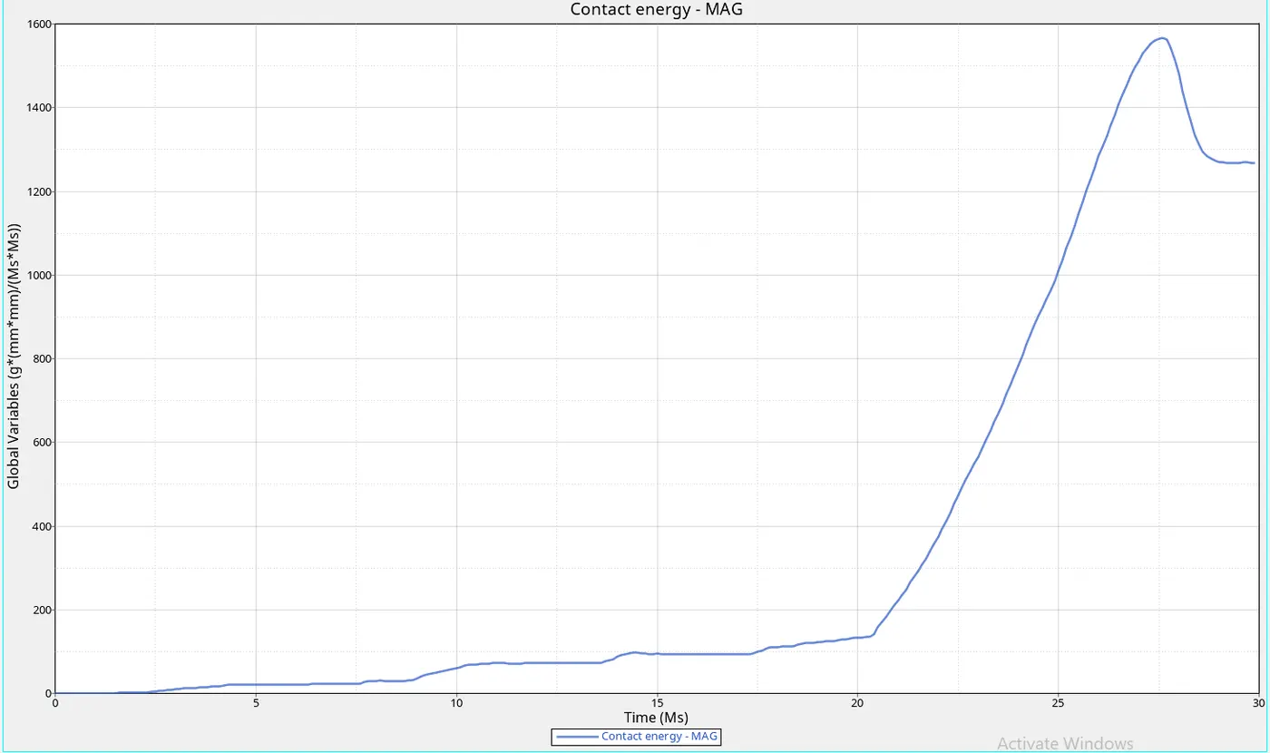
- In this, the component produces less internal energy is reduced with respective of case 1 and case 3
- But the meeting point of internal energy is a high form that we can consider the delay in internal energy with respect to the time
MAXIMUM TIME STEP. . . . . . . . . . . . . . . . 0.1000000E+31
CYCLE TIME TIME-STEP ELEMENT ERROR I-ENERGY K-ENERGY T K-ENERGY R EXT-WORK MAS.ERR
TOTAL NUMBER OF CYCLES: 83496
STARTER+ENGINE RUNTIME = 371.88s (00:06:11)
CASE 5:-Create a new notch in the middle, select the whole section and run
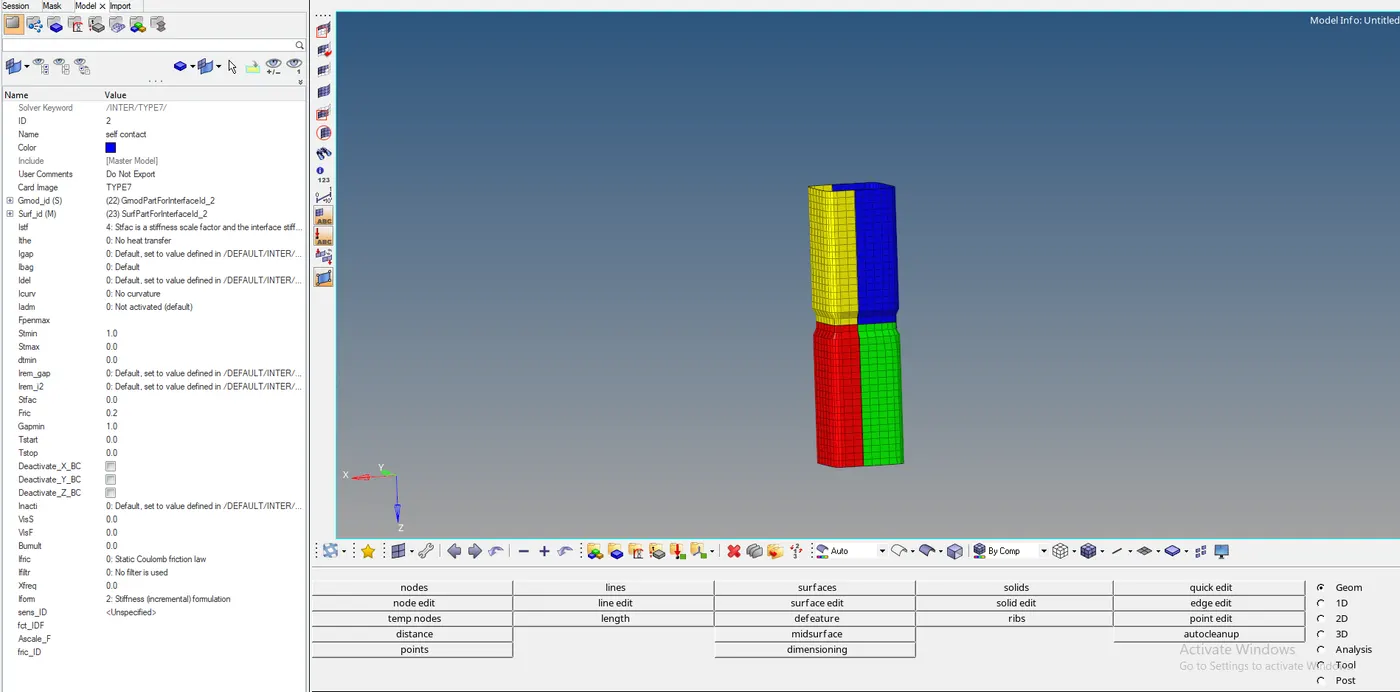
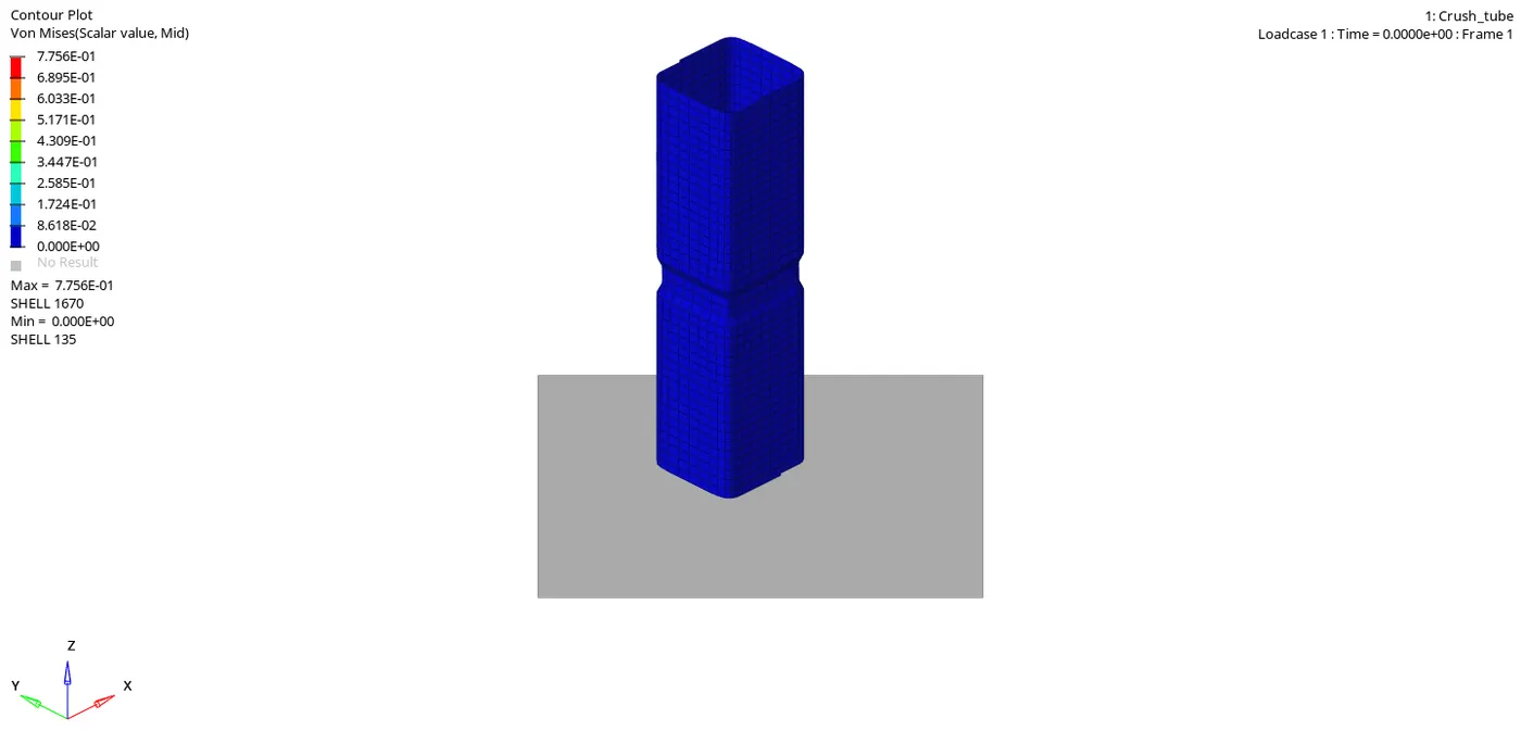
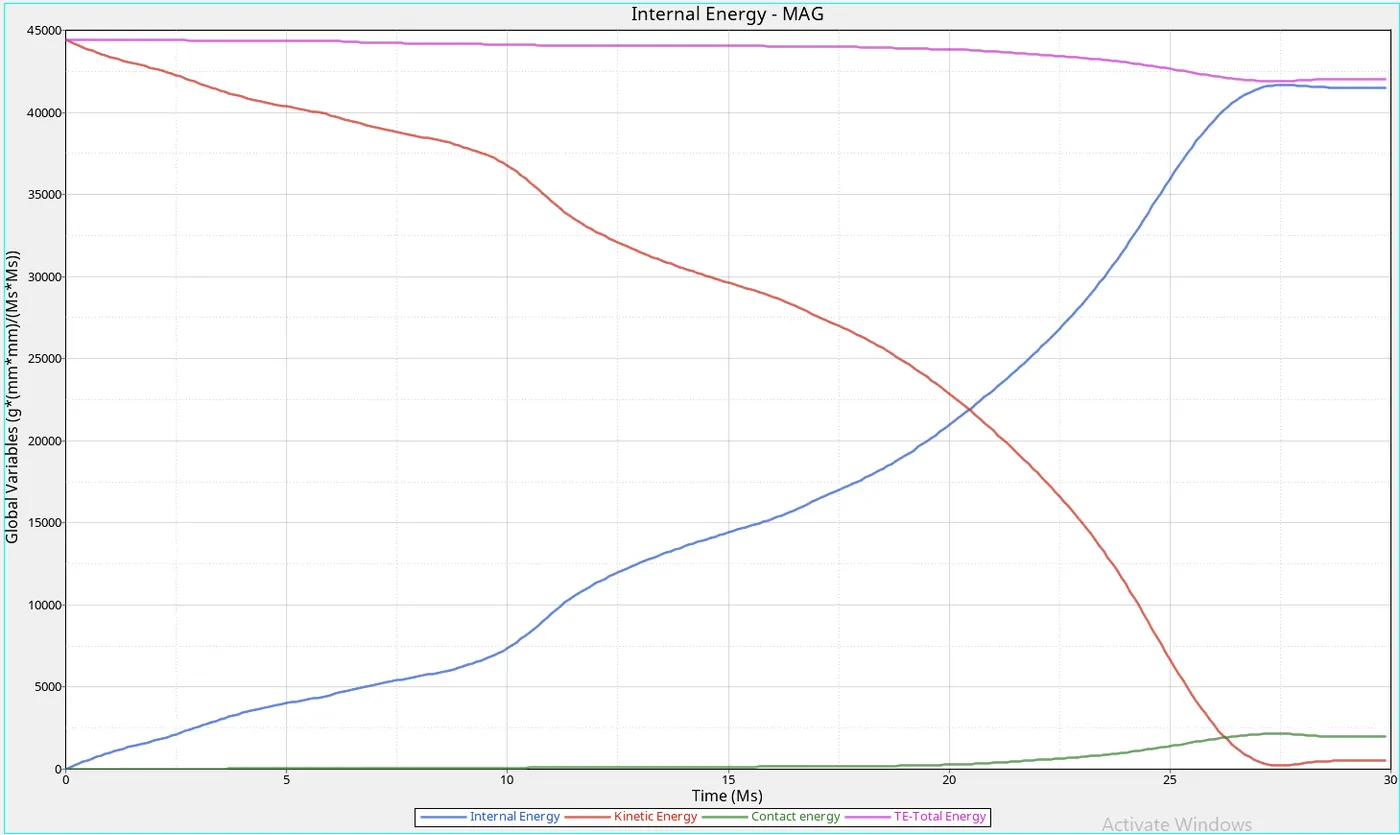
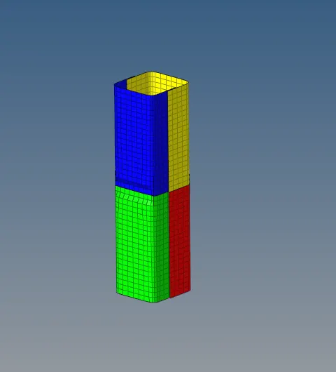
- In this, we made the notch at the center so that the generation of internal energy is less with respective case 4
- Because it observes a lot of force due to notch and stores so that there will less chance of failure
CYCLE TIME TIME-STEP ELEMENT ERROR I-ENERGY K-ENERGY T K-ENERGY R EXT-WORK MAS.ERR
101500 29.97 0.2461E-03 SHELL 1644 -4.5% 0.4151E+05 512.2 0.5217 -385.4 0.000
101600 30.00 0.2461E-03 SHELL 1644 -4.5% 0.4151E+05 512.2 0.4831 -385.4 0.000
TOTAL NUMBER OF CYCLES : 101618
STARTER+ENGINE RUNTIME = 428.37s (00:07:08)
MAXIMUM TIME STEP. . . . . . . . . . . . . . . . 0.1000000E+31
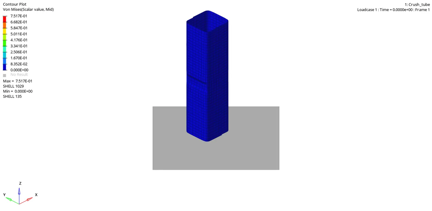
CASE 6:-Create a new notch with nodes only from opposing 2 faces and run.
CYCLE TIME TIME-STEP ELEMENT ERROR I-ENERGY K-ENERGY T K-ENERGY R EXT-WORK MAS.ERR
88900 29.95 0.1944E-03 SHELL 1644 -4.0% 0.4182E+05 523.0 0.1612 -294.6 0.000
89000 29.97 0.1944E-03 SHELL 1644 -4.0% 0.4182E+05 523.0 0.1571 -294.6 0.000
89100 29.99 0.1944E-03 SHELL 1644 -4.0% 0.4182E+05 523.0 0.1588 -294.6 0.000
TOTAL NUMBER OF CYCLES : 89176
STARTER+ENGINE RUNTIME = 381.65s (00:06:21)
- In this the internal energy of the component is same as above but the time taken for intersection of K.E and I.E is too quick
- So that forces will increase with respective the case 5 but less than case 4
CASE 4 VS CASE 5 VS CASE 6
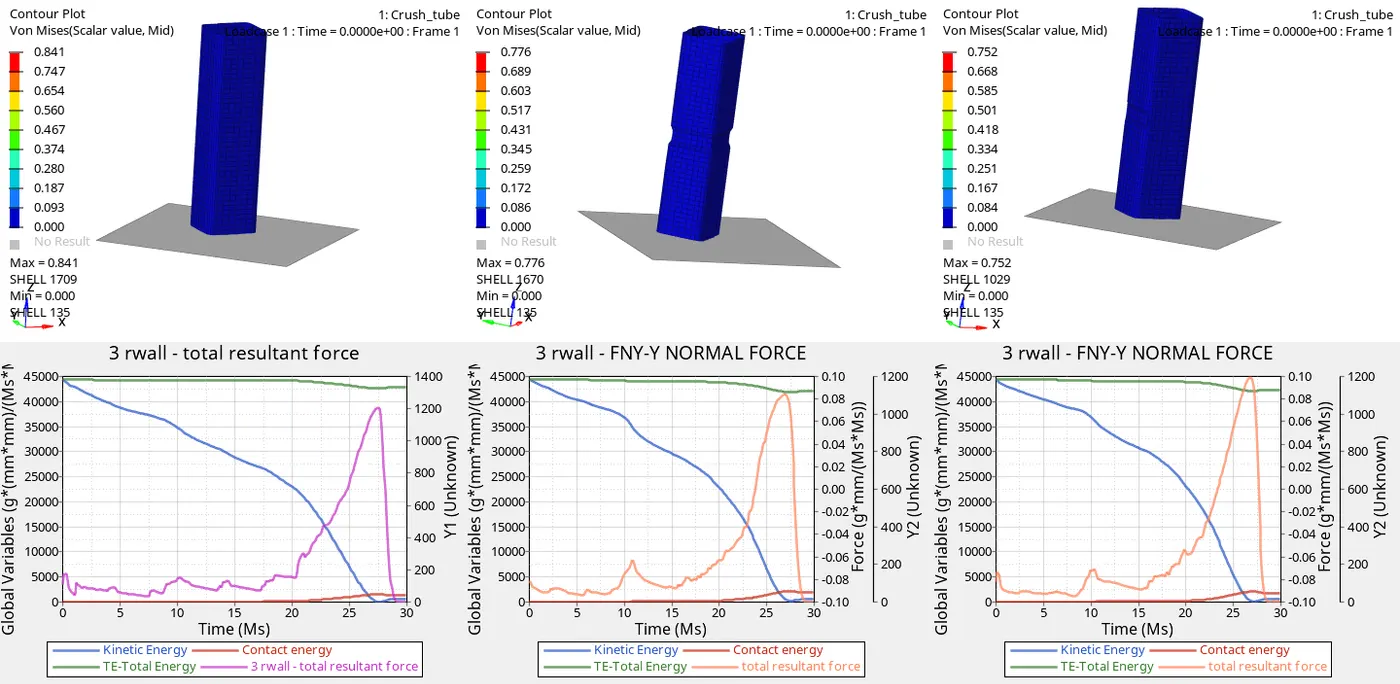
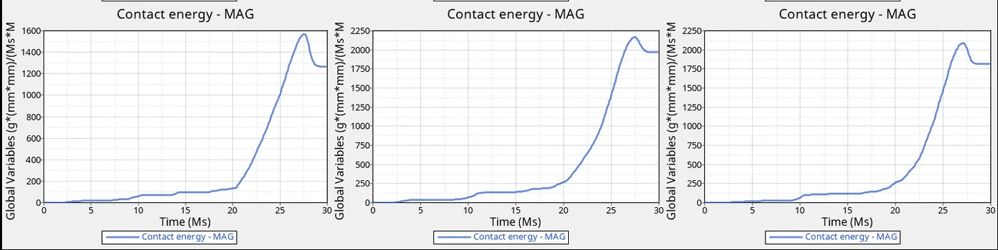
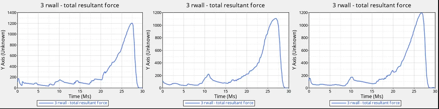
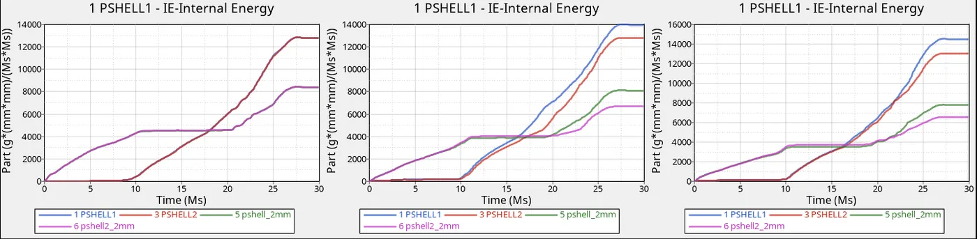
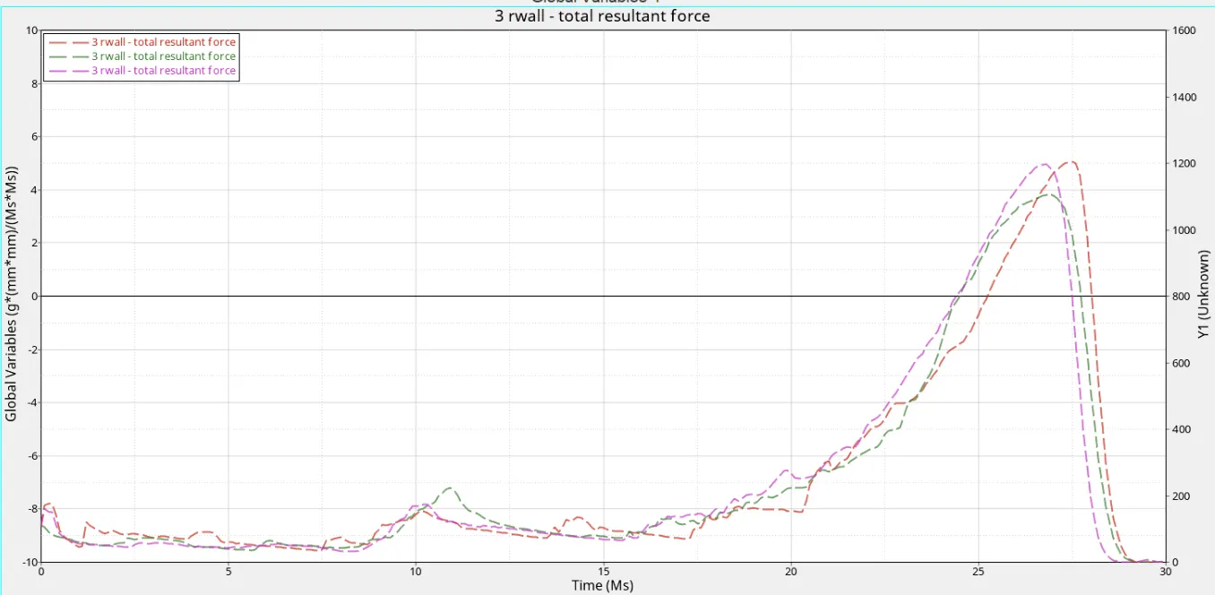
- As we can see that the is change in the rigid wall force
- For case, it undertaking high rigid forces due to flat geometry
- Compare case 5 and case 6 we can see the force for case 5 less because it has notched at the center in all sides the forces are been conserved
- But in case 6 there are notches at the opposite faces that will resist forces from the rigid wall
- We can see the change in the contact energy if there is no notch the penetration is less so that contact is low
- As we can see as the notches increases in faces the contact energy is been increasing due to the penetration
CONCLUSION
- Understood the process to create a connection
- Understood the importance of the interface while performing explicit analysis
- Understood and performed connection to the components
- Compared to the difference and changes when we change parameters and know their importance
- Understood to control the rigid wall force for the component