Interface and Contact Modeling for Crash tube
AIM :-
To create the Mesh on bumper assembly, Interface and Contact Modeling for Crash tube by comparing type 7 and type 11 interfaces with Changing notch position and removing notch .
OBJECTIVES:-
we will be comparing 6 cases here which are
- To change the Inacti=6 and run.
- To run the crash tube model as it is.
- To create the type 11 contact and run.
- To remove both notches and remove boundary condition on rigid body node then run.
- to create a new notch in the middle ,select the whole section and run.
- To create a new notch with nodes only from opposing 2 faces and run.
THEORY:-
- Interfaces are defined to model how parts interacts when they come into contact with each other.
- In any interaction of surfaces or in any situation where two components are colliding to each other there are two terms which are used commonly slave and master.
- Master is going to tell how the slave behaves or we can say that slave is coming in contact with master and slave is the one which obey what motion the master is impoarting on it.
TYPES OF INTERFACES
- Type 2 : tied node to surface
- Type 7 : Nodes to surface contact
- Type 11 : Edge to Edge Contact
- Type 24 : General node or surface to surface Contact
Here we are using only 2 interfaces TYPE 7 & TYPE 11
PROCEDURE:-
1 :- To Create the mesh for bumper assembly,mesh size should be 6mm.
- Import the model bumper assembly
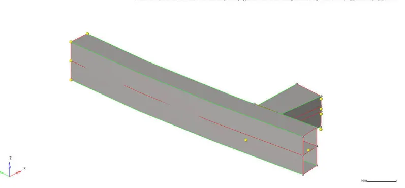
- And then we have to do geomentry clean up
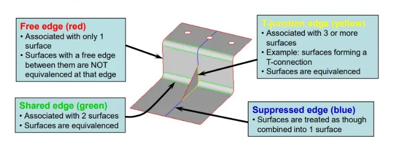
- We have to fix these free edges T joints etc... by using these tools Tools>Edge Edit Panel
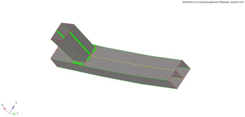
- After geomentry clean up we have to spot weld the crash box upper and lower and crash box to the bumper the below fig shows the after all process is done
- 2D AUTOMESH geomentry>>2D>>automesh the automesh panal shown below

- Automesh panal is set as shown in the above image
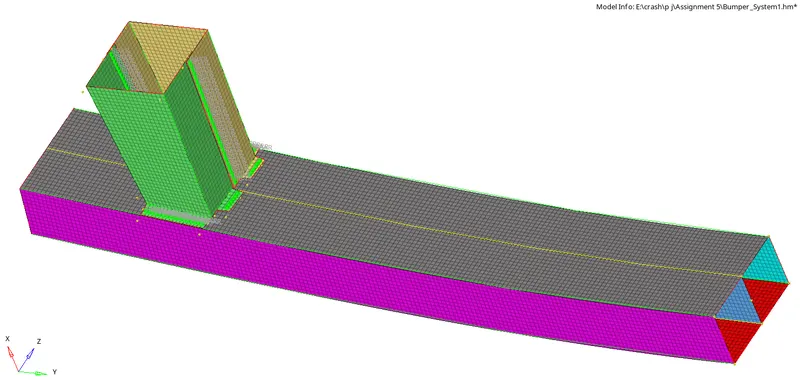
- And then select the surface and click on the mesh and do it one by one below fig shows after the meshing the model
2 :- Interface and Contact Modeling for Crash tube by comparing type 7 and type 11 interfaces with Changing notch position and removing notch .
Case 1 :-
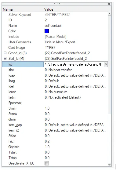
- In Case 1 we have run model as it is with inter face type 7 with all default condition with Stmin 1.0 and Gapmin is 1.0 an Istif is 4 i.e Interface stiffness is the minimum of the master and slave stiffness shown in the fig 1.1.
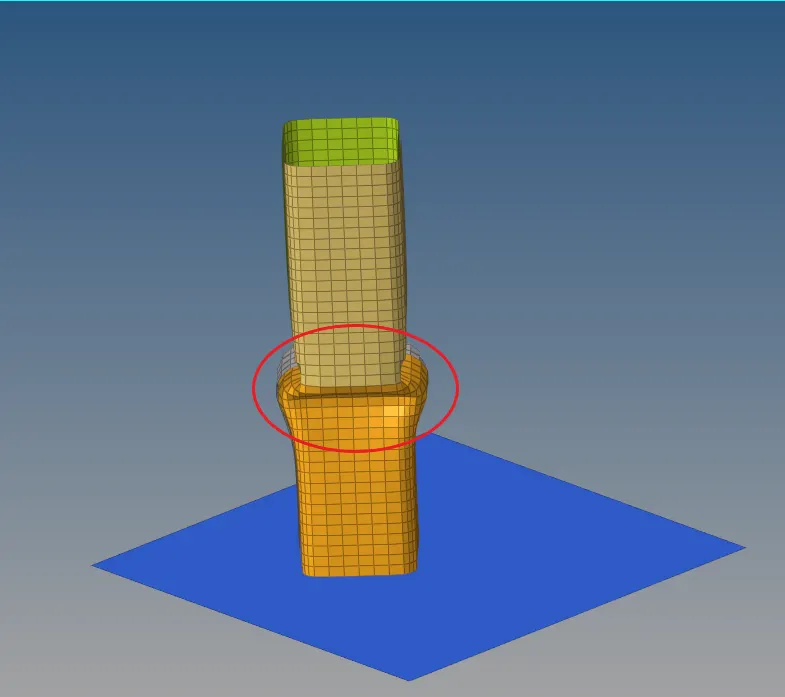
- Deformation takes place first at the notch as we can see that in the below fig
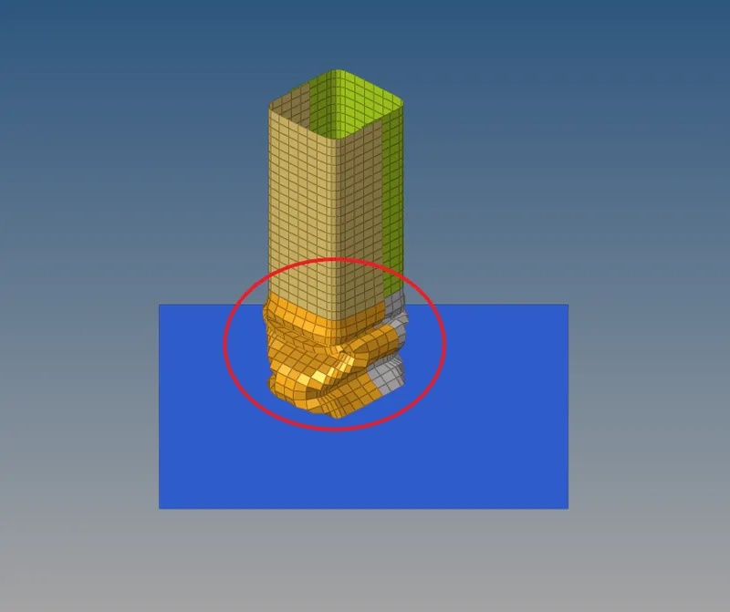
- Velocity is in the direction of thr rigid wall after crush tube hitting the wall the deformation is happending on the notch area
-
Deformation takes a notch which is near to the middle of the model due to applied velocity.
-
After complete deformation of the notch. The next deformation occurs at a notch which is near to the Rigid wall this is because the thickness is less at bottom. This notch is formed in fillet areas so because that notch region is going inside and which are flat elements are coming out, this region does not require more force to deform.
- We can see the simulation of contact forces below
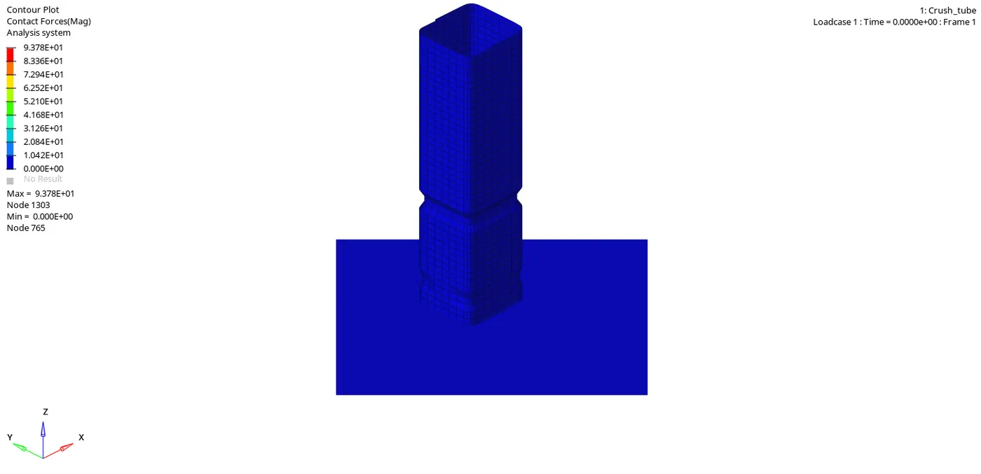
- Max contact force is 9.378E+01 on node 1303
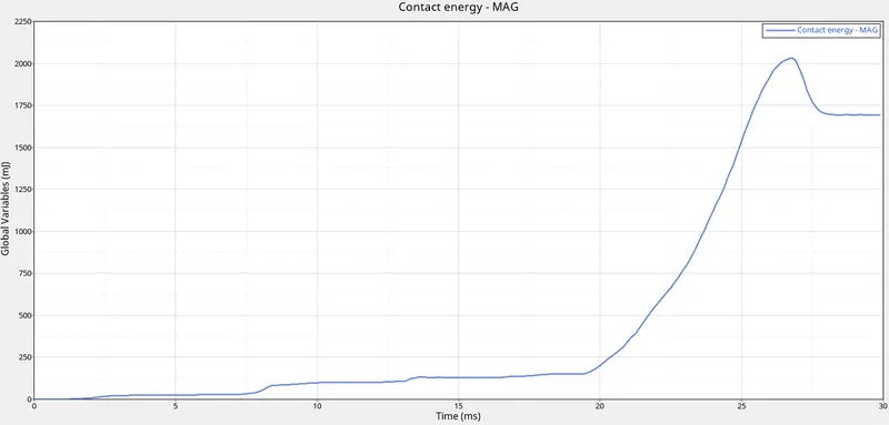
CONTACT ENERGY
- Initially the contact energy is low at the end the contact energy is high becauce of the more contact in the nodes and elements at the end as we see in the simulation
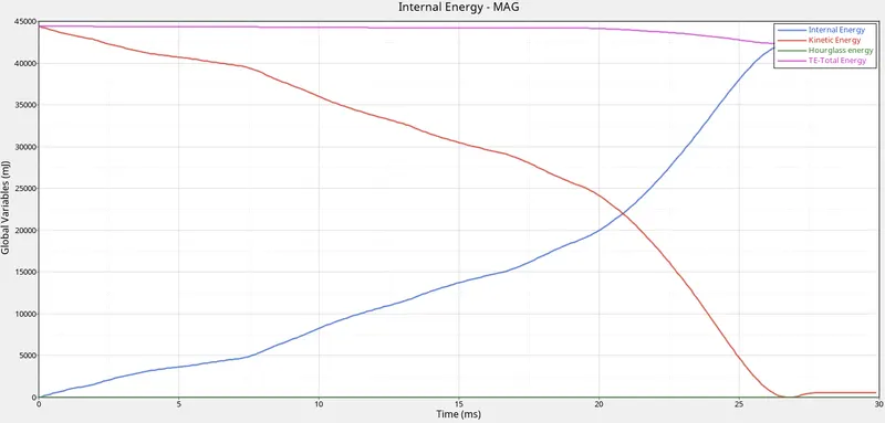
- Below Graph shows the TE ,IE ,KE ,HG
-
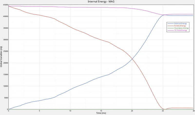
Initially the velocity is maximum so the Kinetic energy is maximum. when impact takes place the KE is absorbed by part, so that KE is decreasing and internal energy is increasing.
-
After 80% deformation theKE is absorbed by part more so we can see the sudden decreasing in the KE, and Sudden increasing in the Internal energy
-
Once deformation reaches max, due to rigid wall stops velocity so KE becomes zero and internal energy becomes max value.
-
Initially the contact energy is zero, once velocity is applied and deformation starts due to this deformation there will be penetration, to overcome against penetration the forces are building as per the given Gap min, due to that force we can see the contact energy.
- Rigid wall forces are initially minimum and then the forces are increased as the crush tube and then decreased that the veloicty is decreased
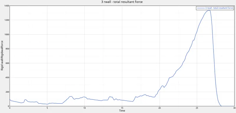
Rigid wall forces
Case 2 :-
-
Special treatment for initial penetrations can be accomplished through the use of the Inacti . It is possible to remove penetrated nodes from the interface or to remove the master segments relating to the penetrated nodes. Both treatments allow getting rid of initial penetrations very easily, but they may lead to poor results if the number of penetrated nodes is large.
-
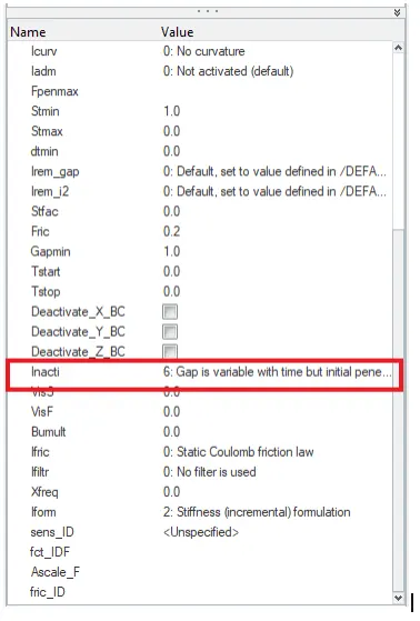
In this case we are changing Inacti to 6 in type 7 Interface. Action to take if initial penetrations exist or Remove initial penetration where possible elsewhere reduce to less than 30% of the defined gap value an adjust the gap with Inacti
- We can see the contact force simulation below
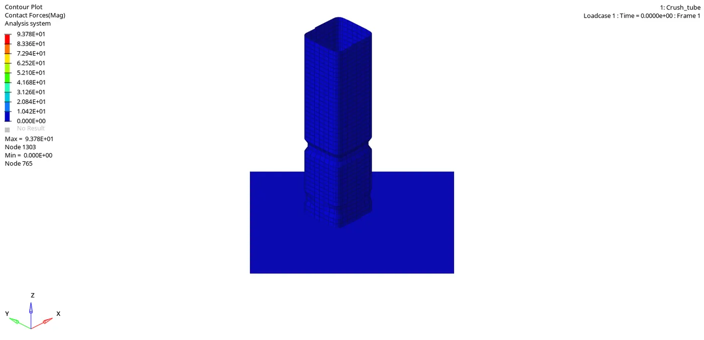
- Here the contact forces and the energis all are same because in CASE 1 also there no penetrations in this model so there no initial penetrations
- Below graph shows the contact energy whuch is same as CASE 1
CONTACT ENERGY
- Below Graph shows the TE ,IE ,KE ,HG
- lly in the rigid wall forces as same as case1
RIGID WALL FORCES
Case 3 :-
- To Create the type 11 contact and run.
-
This interface simulates impact between edge to Edge or lines. A line can be a beam or truss element or a shell edge or spring elements.
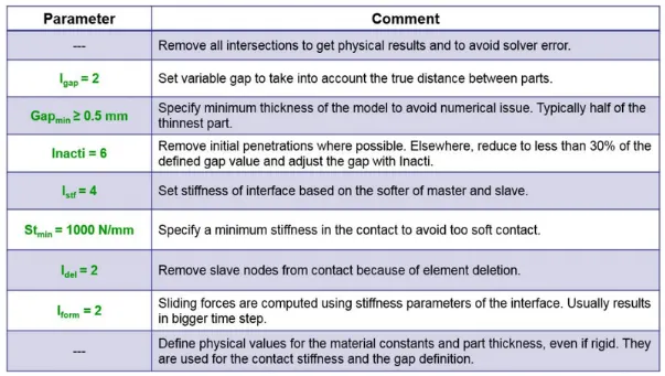
- For type 11 contact recommonded parameters are shoen below
RIGID WALL FORCES CONTACT ENERGY
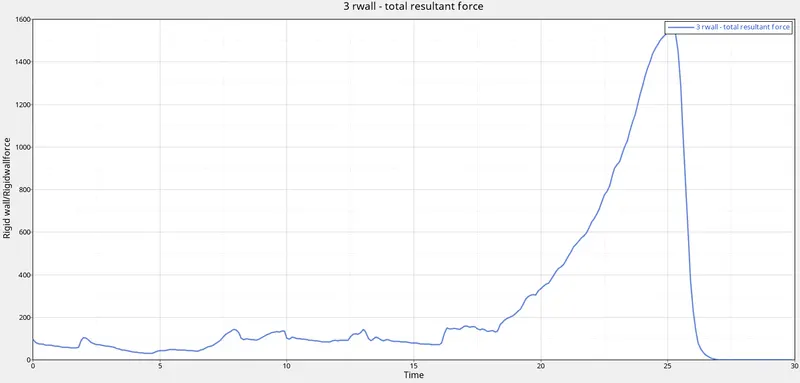
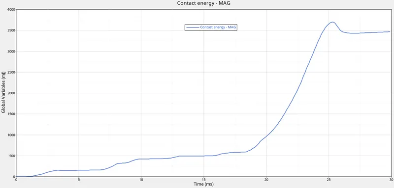
- Here we can see the both contact energy and rigid wall forces are increased compare to the CASE 1 & 2 because Istiff = 4 Interface stiffness is the minimum of the master and slave stiffness.
-
Due to less stiffer the contact energy produced to over come on interface is more so we can see the contact energy is more with less time compare to case 1
- Below Graph shows the TE ,IE ,KE ,HG
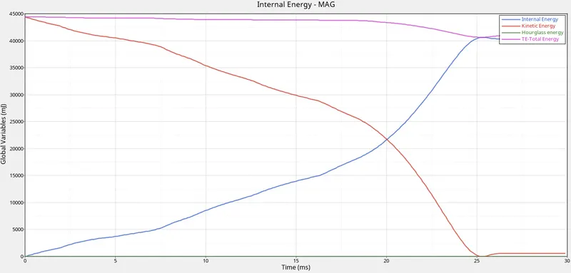
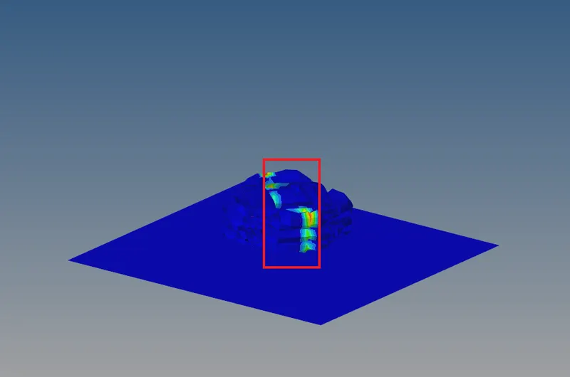
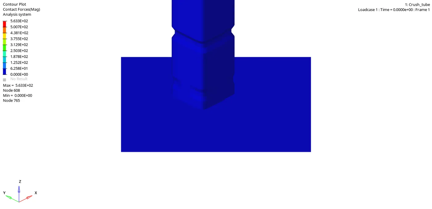
- We can see the simulation of the contact energy
Case 4 :-
- Remove both notches and remove boundary condition on rigid body node then run.
- Because fo no notch in the model the deformation is occur from the bottom of the crush tube where the crush tube starts hitting to the wall
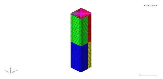
- We can see the simulation after removing the all notches
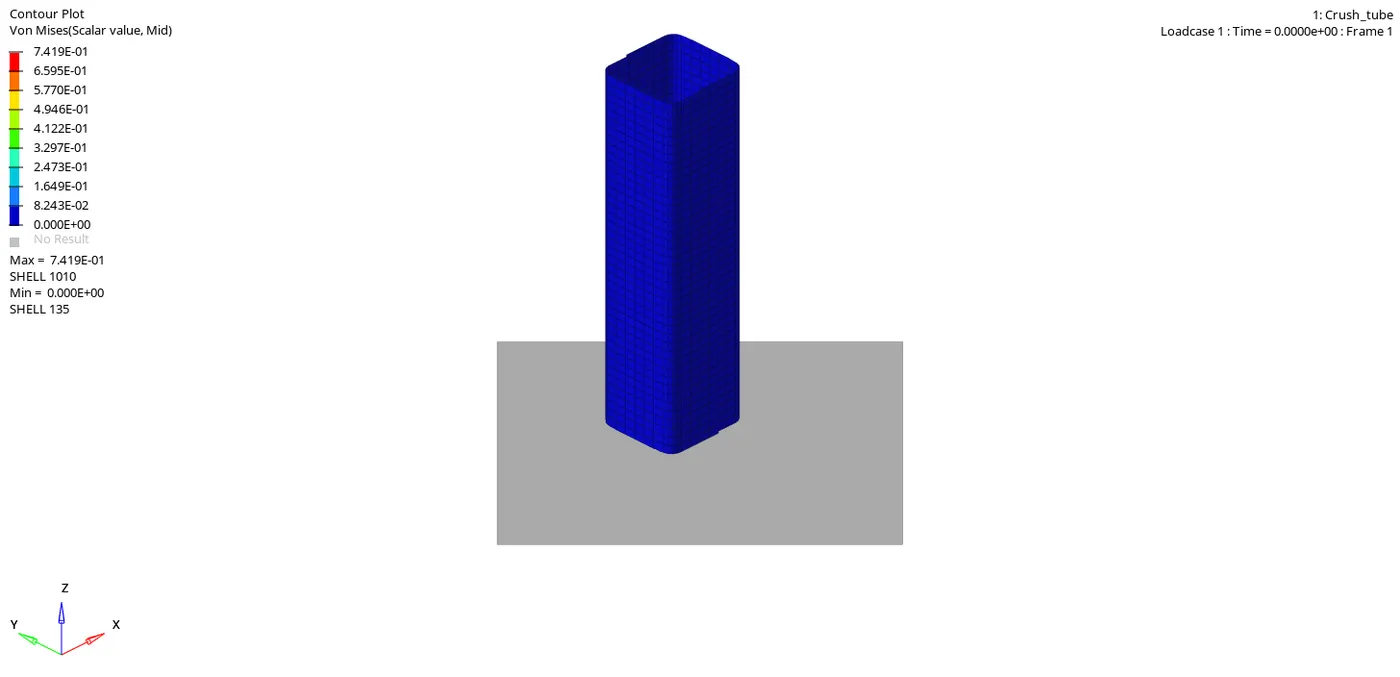
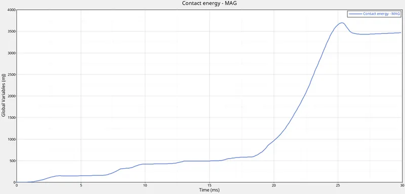
- By removing of notch,the model become more stiffer compare to the case 1 the time taken for the simulation is more than compare to the CASE 1 AND CASE 2
CONTACT ENERGY RIGID WALL FORCES
- And the contact energy and the rigid wall forces are same as the CASE 3
- Below Graph shows the TE ,IE ,KE ,HG
Case 5 :-
- Create a new notch in the middle ,select the whole section and run.
-
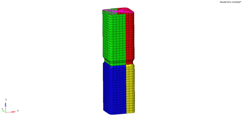
Deformation takes at middle notch of model due to applied velocity due to stress concentration near notch
- We can see the simulation the deformation which occurs at the middel where the notch is
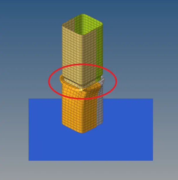
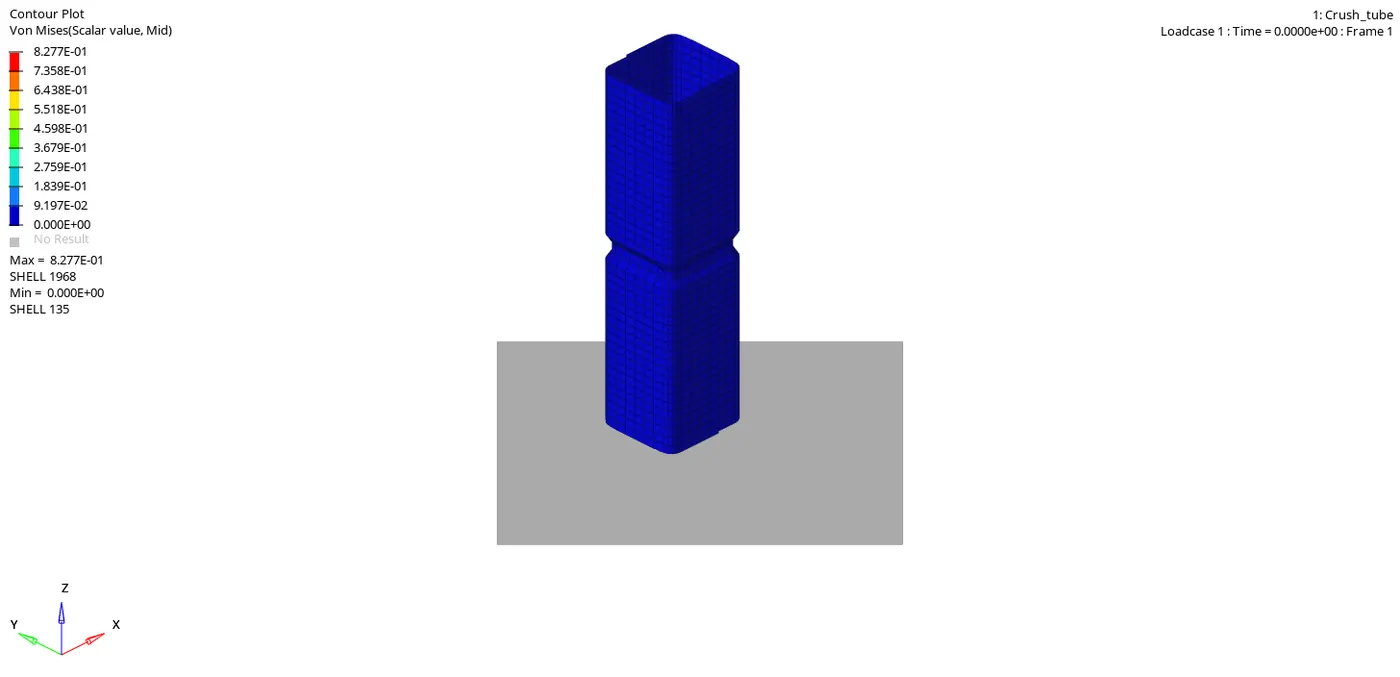
- As we can see the simulation the deformation is happening at the notch so the notch plays an imp role in the deformation
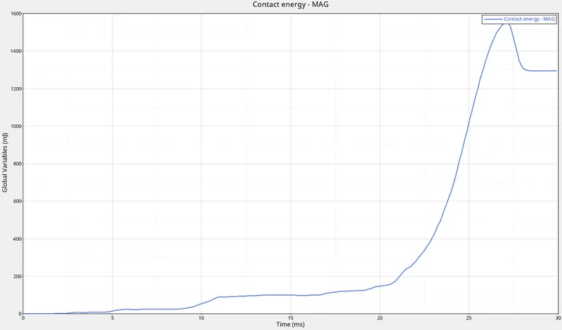
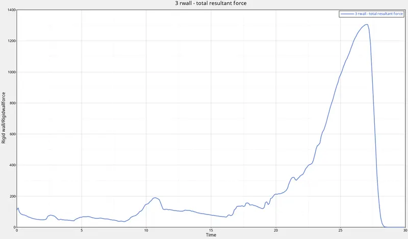
CONTACT ENERGY RIGID WALL FORCES
- The contact energy is less in this case because of the midnotch where the deformation is occure before it deform from bottem where the crush tube hit the wall and rigid wall forces same as the prevoius cases
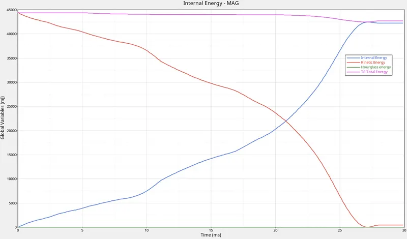
- Below Graph shows the TE ,IE ,KE ,HG
Case 6 :-
- Create a new notch with nodes only from opposing 2 faces and run.
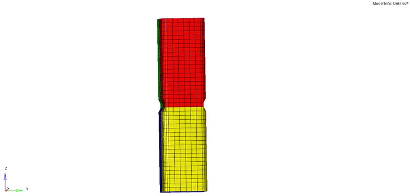
- As we know the notch will initiate the deformation in the model so then this type of notch will deform as shown in the below fig
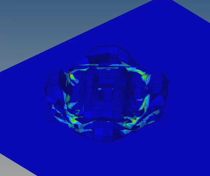
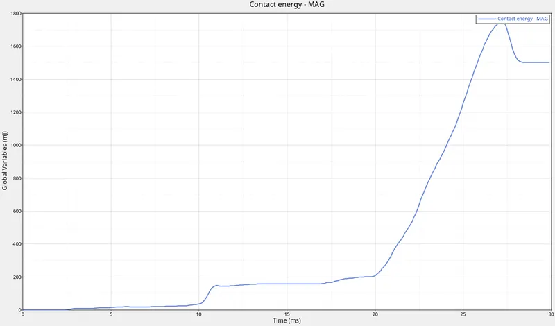
- Below fig shows the contact energy on the model at the end of the simulation
- We can see the simulation below that the model will deform starts from the notch
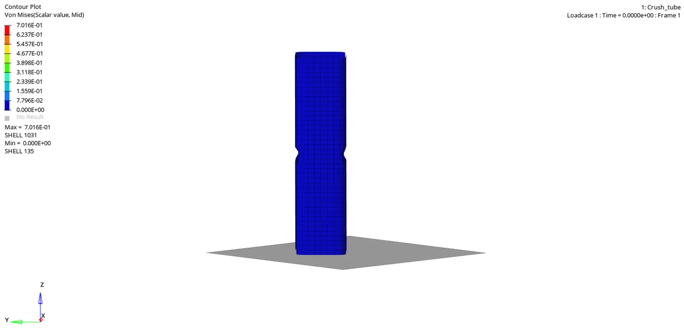
- After complete deformation of the notch. next deformation is occur at bottom which is near to the Rigi wall
CONTACT ENERGY RIGID WALL FORCES
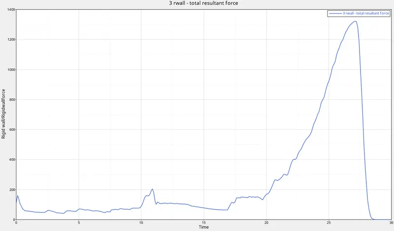
- In CE and RWALL FORCES almost same and the time take in bit more than case 5 midnotch so the case 6 is more stiffer than case 5
- Below Graph shows the TE ,IE ,KE ,HG
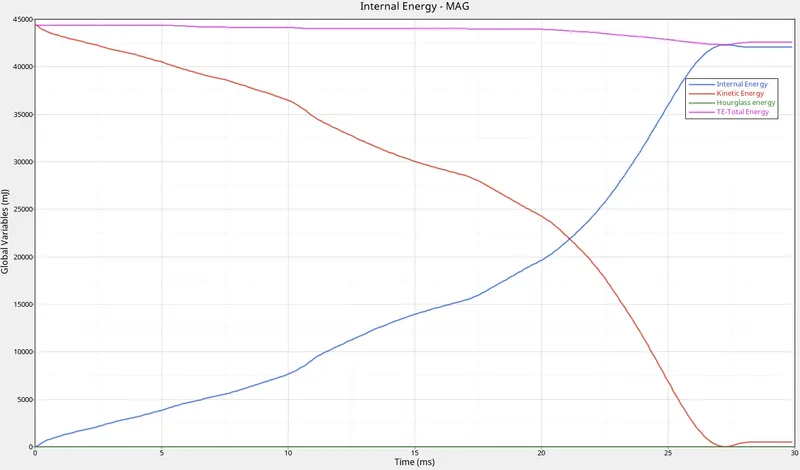
- case 6 is less stiffer to compare case 4 but more stiffer to compare case 5
CONCLUSION :-
- Notch plays an important role in the deformation of the model
- Contact Interface effects on the contact energy as well as notch also