Crash tube analysis in hypercrash.
BUMPER_ASSEMBLY
AIM:-
To generate mesh for bumper assembly with size of 6mm.
SOFTWARE:-
HYPERWORKS
PROCEDURE:-
Firstly import the model to the graphical screen.
After the model is imported check for the geometry cleanup.
Goto > Geom > Quick edit or F11.

After the geometry cleanup, generate mesh.
Goto > 2D > Automesh or F12.
Select the surfaces, set the mesh size to 6mm and mesh.
After meshing is completed check for the mesh flow and edges.
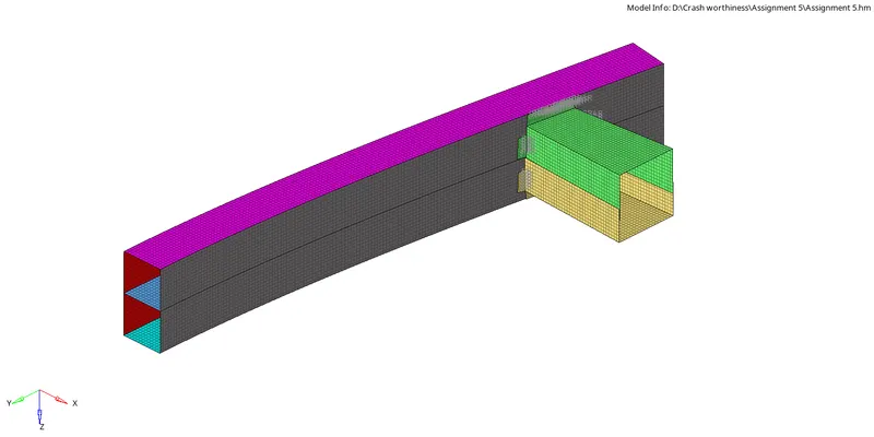
Save the file in .hm format.
RESULT:-
The given model is meshed with a given size 6mm.
CRASH TUBE
AIM:-
To run 6 different cases by making changes in model as well as parameters and plotting graphs on energies.
SOFTWARE:-
HYPERWORKS
PROCEDURE:-
Firstly, set the user profile in RADIOSS.
Import the solver deck file.
CASE 1
After the file is imported, run the file as it is with out make any changes
Goto > Analysis > RADIOSS
Select the save as folder as case 1, enter the option value as -nt 4 and radioss.
After the case is run, open the hypergraph to plot the graphs.
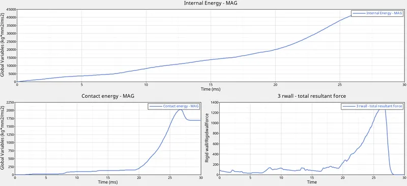
Open .h3d file in hyperview.
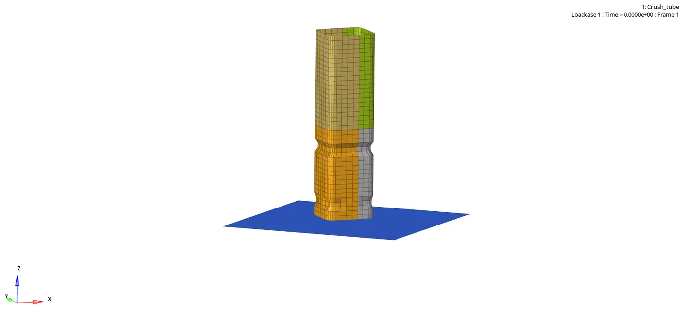
CASE 2
In this case change the value of Inacti = 6.
Goto > model bar > Groups > Self contact.
Inacti It will deactivate the stiffness as in this case the value 6 represent gap is variable with time, but initial penetration is computed as the node is slightly depenetrated.
Goto > Analysis > RADIOSS
Select the save as folder as case 1, enter the option value as -nt 4 and radioss.
After the case is run, open the hypergraph to plot the graphs.
Open .h3d file in hyperview.
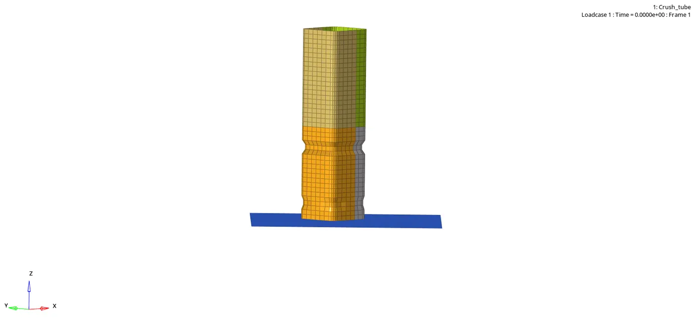
CASE 3
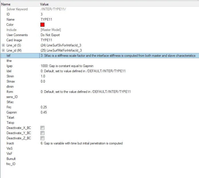
In this case we are creating and assigning Type11 contact to the component.
Goto > Model bar > groups.
Create a new contact by right clicking on the group and assign the values.
Istif = 4
Which represents interface stiffness is the minimum of the master and slave stiffness.
Igap = 1000
Which represents a gap that is constant equal to Gapmin.
Idel = 0
Which represents Node and segment deletion flags ,set to the value defined in DEFAULT.
Stmin = 1.0
Which represents minimum stiffness.
Stmax = 0
Which represents maximum stiffness.
Iform = 0
Which Represents friction penalty formulation type.
Fric = 0.25
Which represents Coulomb friction.
Gapmin = 0.45
Which represents the minimum gap for impact activation.
Inacti = 6
Goto > Analysis > RADIOSS
Select the save as folder as case 1, enter the option value as -nt 4 and radioss.
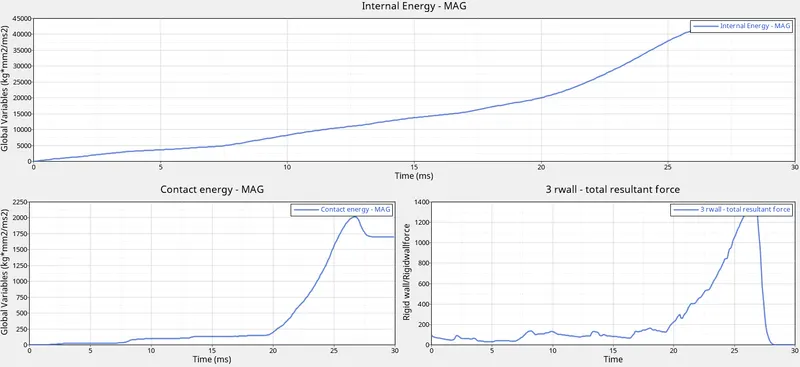
After the case is run, open the hypergraph to plot the graphs.
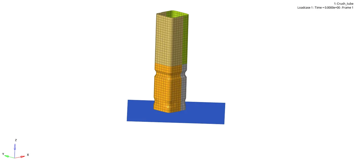
Open .h3d file in hyperview.
CASE 4
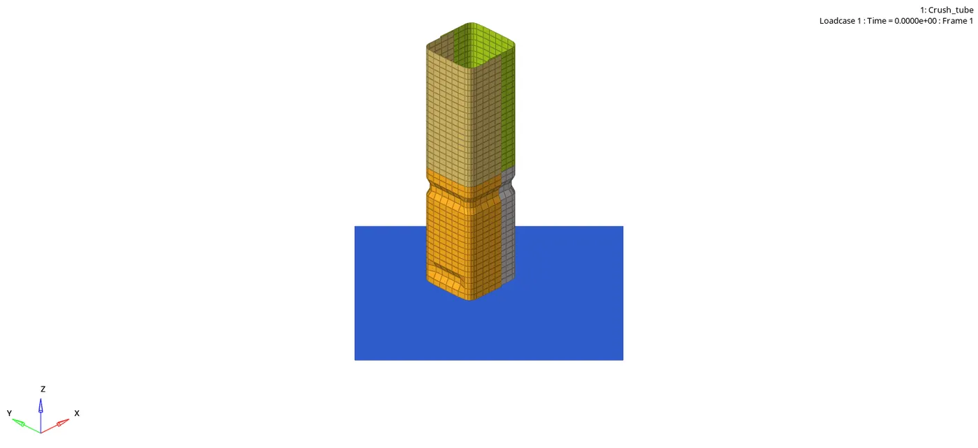
In this case we need to remove the notches of the crash tube.
Goto > Toolbar > Delete or F2.
Select the notch elements and delete.
After Deleting the notches create the plane mesh.
Goto > 2D > Ruled.

Select the node by path option select one end and the other end and middle click.
After the created elements, run the simulation.
Delete the boundary conditions system.
Goto > View > Hypermesh > Solver.
Select the solver tab, delete the BCS file.
Goto > Analysis > RADIOSS
Select the save as folder as case 1, enter the option value as -nt 4 and radioss.
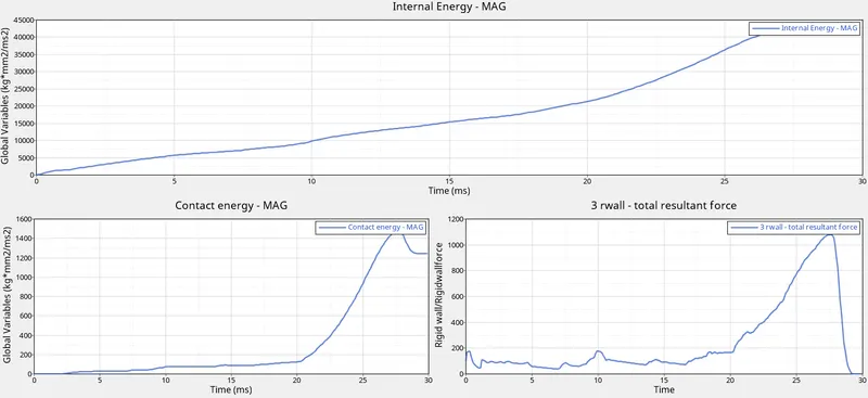
After the case is run, open the hypergraph to plot the graphs.
Open .h3d file in hyperview.
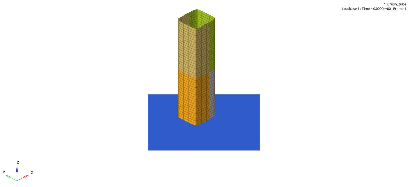
CASE 5
In this case create a notch in the middle of the crash tube.
Goto > Tools > Translate or Shift+F4.
Select the nodes of the elements and keep the vector in the X axis of global variation.
Enter the magnitude value as 4.094 and translate.

Similarly for the edges select the vector N1 one the curve edge and N2 on the opposite edge of the component.
After creating a notch in the middle, run the simulation.
Goto > Analysis > RADIOSS
Select the save as folder as case 1, enter the option value as -nt 4 and radioss.
After the case is run, open the hypergraph to plot the graphs.
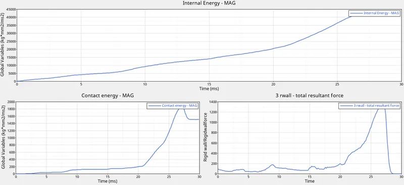
Open .h3d file in hyperview.
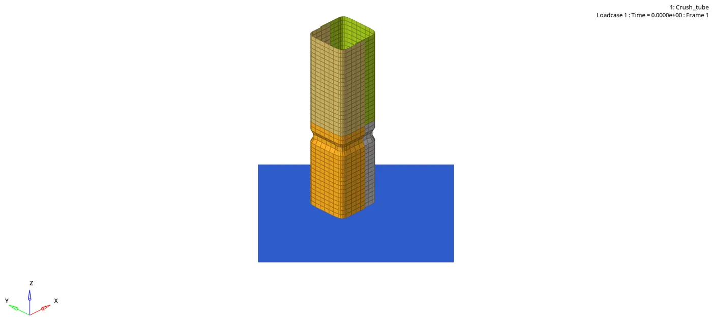
CASE 6
In this case we need to create a notch opposite to each other.
Goto > Tools > Translate or Shift+F4.
Select the nodes of the elements and keep the vector in the X axis of global variation.
Enter the magnitude value as 4.094 and translate.
After creating a notch in the middle, run the simulation.
Goto > Analysis > RADIOSS
Select the save as folder as case 1, enter the option value as -nt 4 and radioss.
After the case is run, open the hypergraph to plot the graphs.
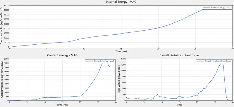
Open .h3d file in hyperview.
Explanation:-
The internal energies are changing.
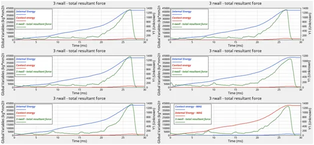
In case 1,2,3 and 6 the internal energy is the same.
As the first two cases are the same just a small change in the Type 7 contact Inacti value.
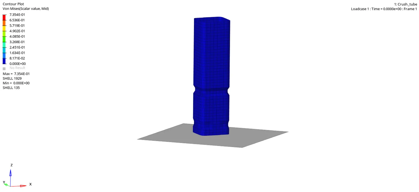
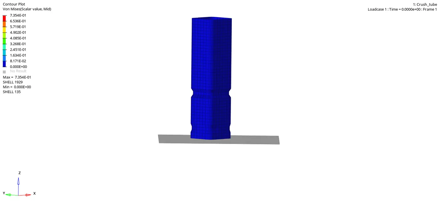
In case 3, we change the interface to type11 contact which increases the rigid wall forces due to less edge to edge contact in the body. We have changed contact type to Type 11 due to the removal of notch the rigid wall force is increased.
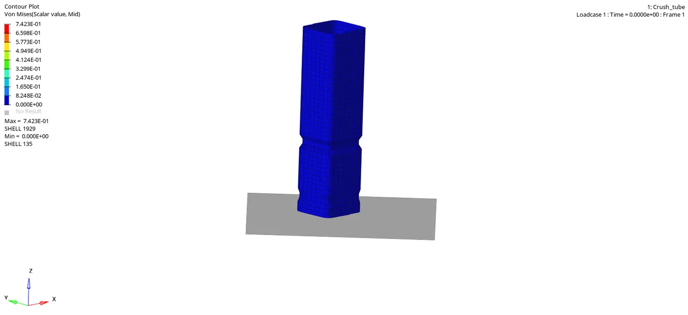
In case 4, after removing the notches and boundary condition of the rigid wall. The rigid forces get decreased as boundary condition is removed from the component.
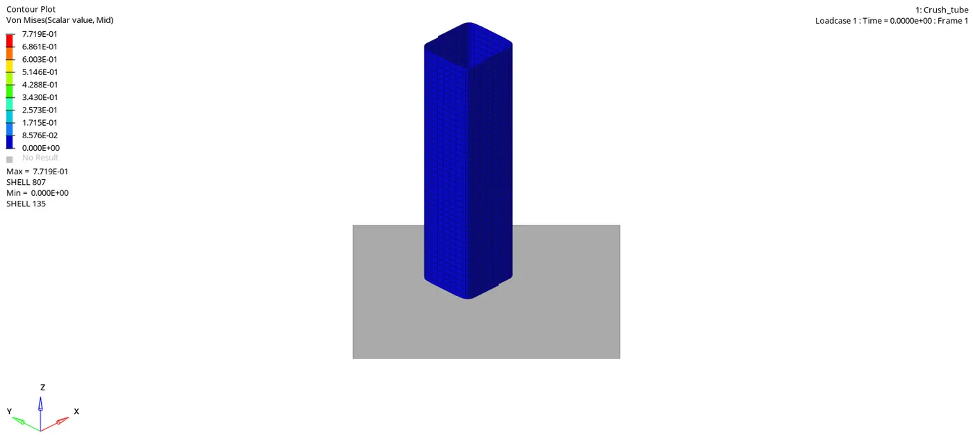
In case 5 & 6, a new notch is created in the middle of the components, as we have deleted the boundary conditions the contact energy and the rigid wall forces increases.
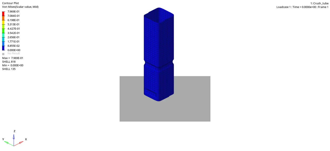
When a notch is present in the body, the notch deforming first then the plane body.
Which results in decrease in contact energy.
When a notch is removed from the body it results in increase in rigid wall force.
We have changed contact type to Type 11 due to the removal of notch the rigid wall force is increased.
Interface Type7: It is a multi-usage impact interface, modeling contact between a master surface and a group of slave nodes. It is also possible to consider heat transfer and heat friction.It does not solve edge to edge contact (to solve this TYPE11 should be used along with TYPE7).
Type 11 interface: This interface simulates impact between edge to Edge or lines. A line can be a beam or truss element or a shell edge or spring elements. This interface can be used in addition to TYPE 7 to solve the edge to edge limitation of interface TYPE7.
RESULT:-
The given model is meshed with an element size of 6mm.
All the crash tube cases have been run the simulation and plotted with the energies graphs.