Assignment 4-RADIOSS Material Laws Challenge
Assignment-4 Case study on different material by using Radioss
Aim :- To simulate the given model with seven different cases in radios as per problem statement and compare it using various plots.
Software used :- Altair hyper-works student version 2020
Problem statement :-
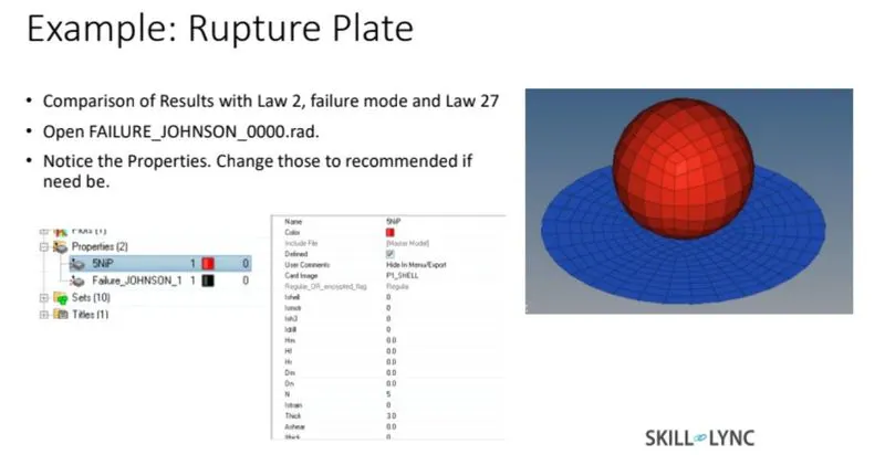
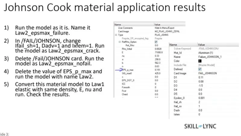
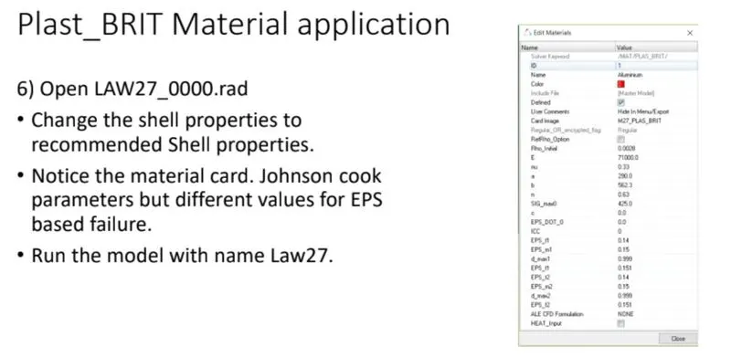
Compare 7 cases as discussed in last 3 slides, in a tabulated format on the basis of:
- Total number of cycles, Energy error, mass error and simulation time.
2. Notice the animation of all 5 and describe the animations in brief on the
basis of whether the elements are being deleted or cracked.
3. Plot energies and notice any difference.
4. Based on all the results, which case would represent the on-field
scenario.
5. Prepare a ppt/docx and list down case-by-case result and your conclusion
as to why the failure happened.
Solution :-
Case 1 :- Law2_epsmax_failure
- Import starter file into radios as shown in image below.
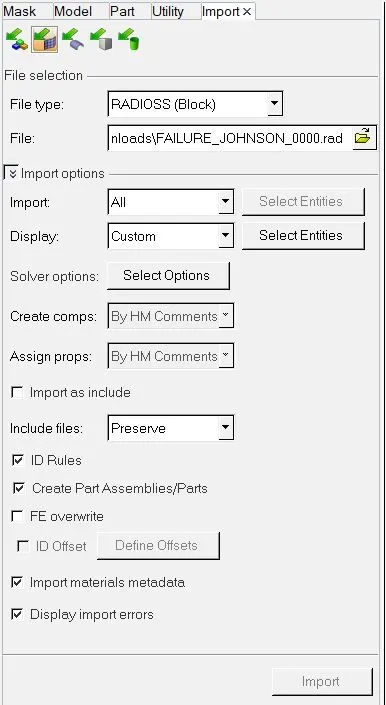
- In this case we have to run the model as it is so select Analysis > Radioss > select path where model need to be saved > select export option as all > run option as an analysis > run number as a1 > type -nt 4 in options for increasing simulation speed > Radioss. It will take few seconds time for calculating simulation.

- Open hyperview to view animation and contour plots from H3d file. The simulation is shown in GIF below.
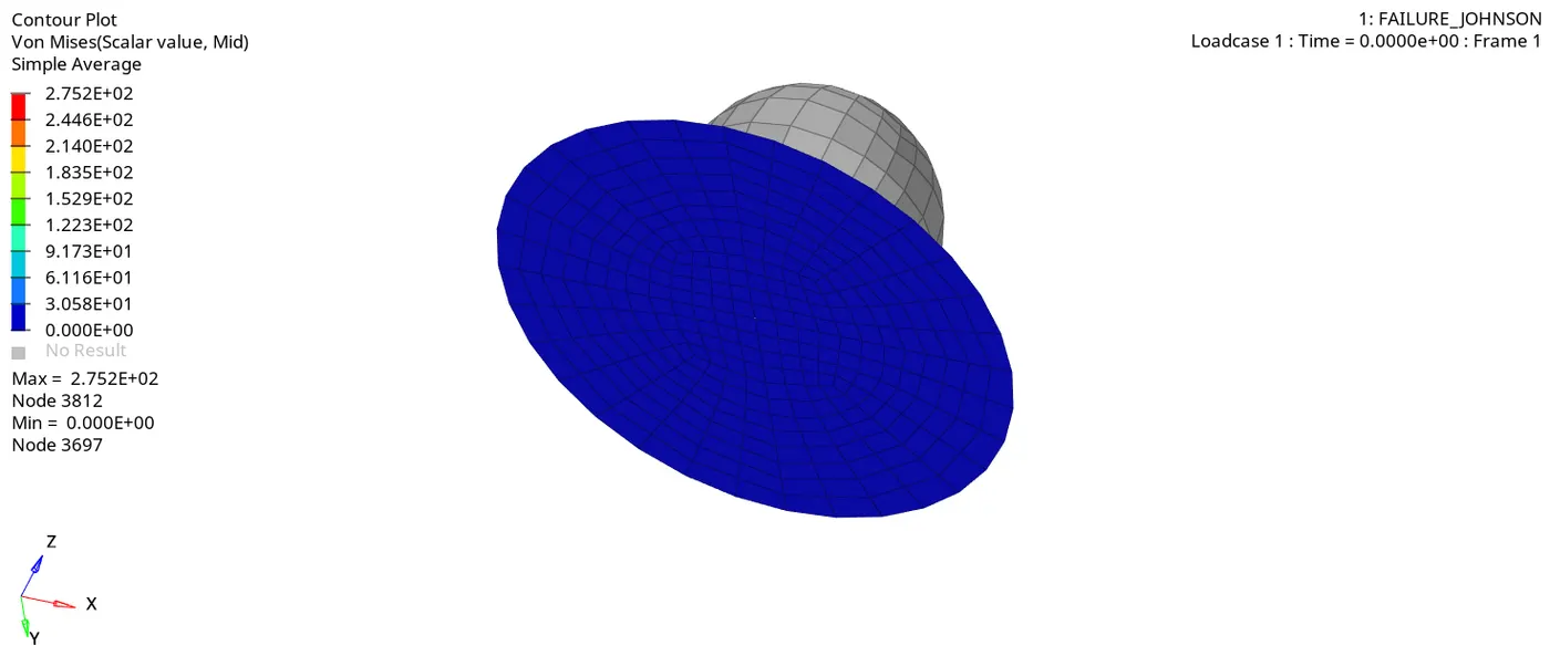
We can observe that elements are getting deleted as the maximum plastic strain values are reached in the elements. But the crack propagation is not generated due to xfem value is not assigned.
- Open output file and check energy error and mass error as shown in image below.
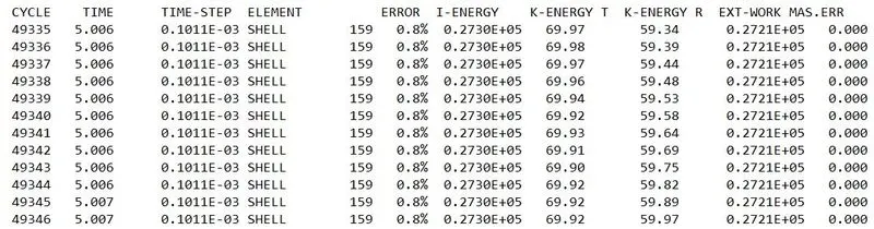
From output file energy error is 0.8% and mass error is 0% which is less than -15% to 2% and 1% respectively, so we can accept the results and plot the graphs by using hypergraphs.
- Open hypergraph 2d for observing the energy plot data from TA01 file.

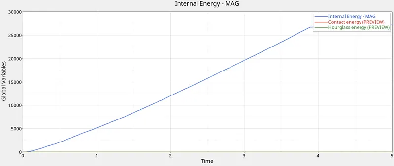
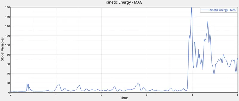
We can observe from the plots that the hourglass energy is zero so recommended properties are correct and Internal energy reaches its peak value just before the elements are getting deleted at 3.9ms.
Case 2 :- Law2_epmax_crack
- Import the law 2 file which will be input file for case 2, and change the failure Johnson parameters as Ifail_sh = 1, dadv = 1, Ixfem = 1
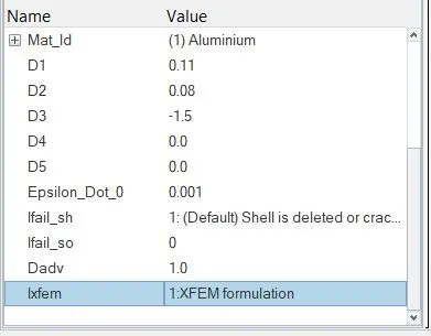
- I fail_sh - Shell failure flag, when the flag is set to 0 the elements get deleted & when the flag is set to 1 the elements get cracked or deleted.
- Dadv - The criteria for crack advancement it is used only with the Ixfem for proper crack capture of the material.
- Ixfem - XFEM is activated (Ixfem=1), the failure criteria will lead to element cracking instead of element or layer deletion.
- The parameter d1, d2 & d3 which provide the data about what mode of strain is required for the element to break.
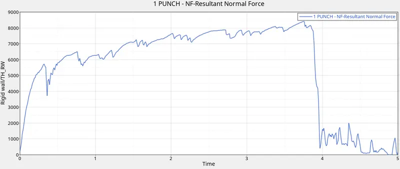
- After changing the parameters run the simulation with same steps to be carried as per previous case. The simulation is shown in GIF below. Plot the graphs of energies and punch resultant normal force.
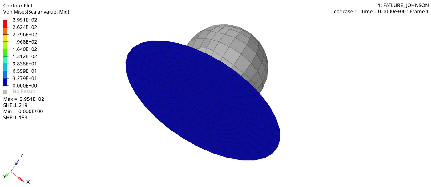
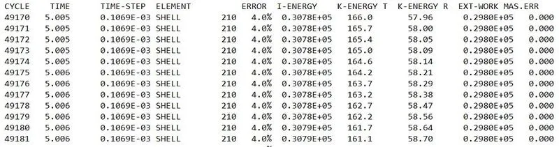
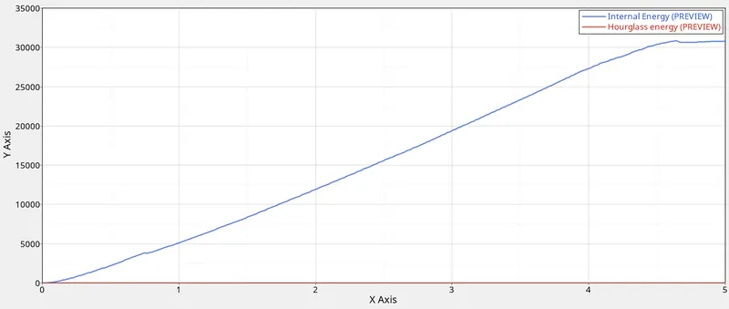
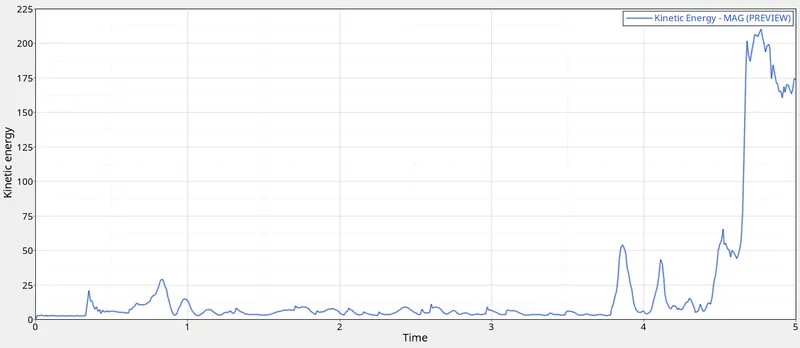
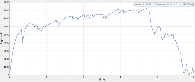
In this case, The simulation shows upto 4.5 ms the deformation of the plate is smooth after that elements are cracked and deleted at the critical point. At that point, the time step as suddenly increases and also the normal force of the punch reaches the max point. The max von moses stress is 295 N/mm2 which exceeds the yield stress and the energy error is 4% means the model is not consistent for this case. The energy dissipation is almost linear upto 4.5ms and remains constant because of the element crack and deletion. The Kinetic energy is varied peak at the time 4.5 ms in which the element deletion is occured, due to element in the edge the energy dissipation is remain constant and some variation in the kinetic energy.
Case 3 :- Law2_epmax_nofail
- For case 3 we have to simulate the model with deleting failure card so delete it by right clicking on failure card and change the name of material card is Law2_epmax_nofail
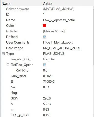
- After changing the parameters run the simulation with same steps to be carried as per previous case. The simulation is shown in GIF below. Plot the graphs of energies and punch resultant normal force.
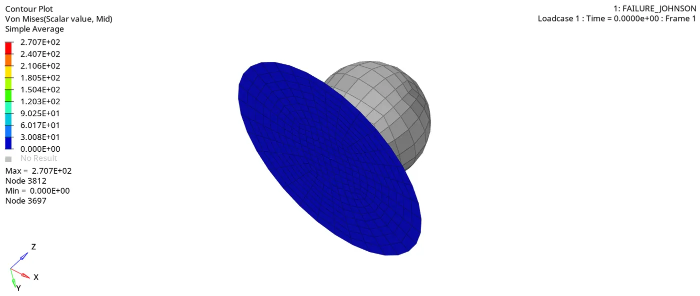
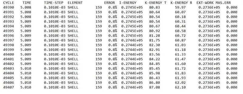
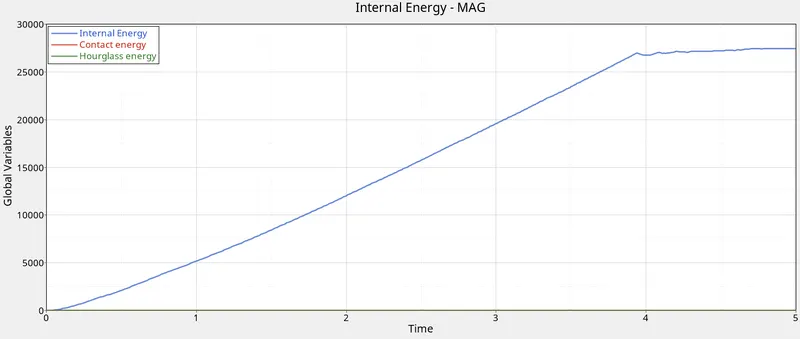
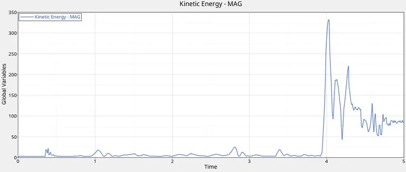
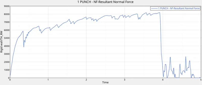
- In this case, the simulation shows up to 4 ms the deformation of the plate is smooth after that elements are cracked and deleted at the critical point. At that point, the time step as suddenly increases and also the normal force of the punch reaches the max point. The max von mises stress is 270 N/mm2 and the energy error is 0.8% means the model is consistent for this case. The energy dissipation is almost linear up to 4ms and remains constant because of the element crack and deletion. The Kinetic energy is varied peak at the time 4 ms in which the element deletion is occurred, due to element in the edge the energy dissipation is remain constant and some variation in the kinetic energy.
Case 4 :- Law2_epmax_nofail
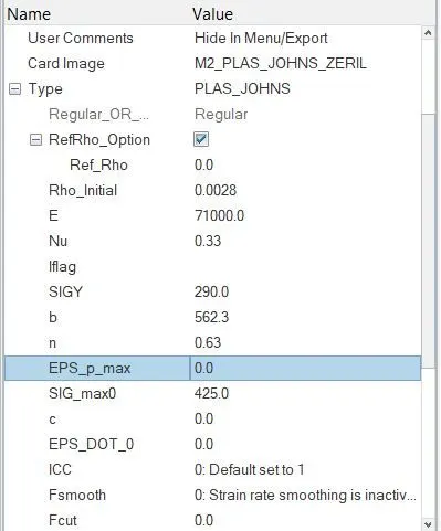
- In this case we have to delete the value of eps_p_max and need to run the simulation with law 2.
- The changes in material card is shown in below image.
3. After changing the parameters run the simulation with same steps to be carried as per previous case. The simulation is shown in GIF below. Plot the graphs of energies and punch resultant normal force.
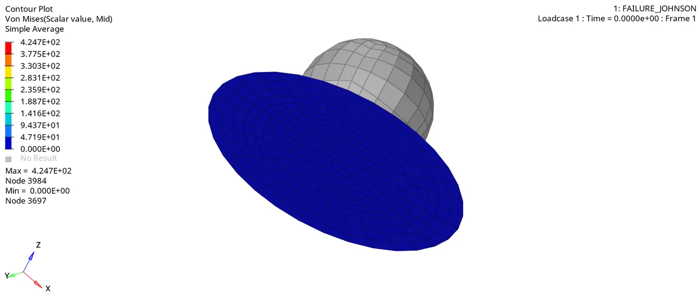

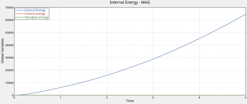
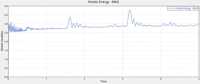
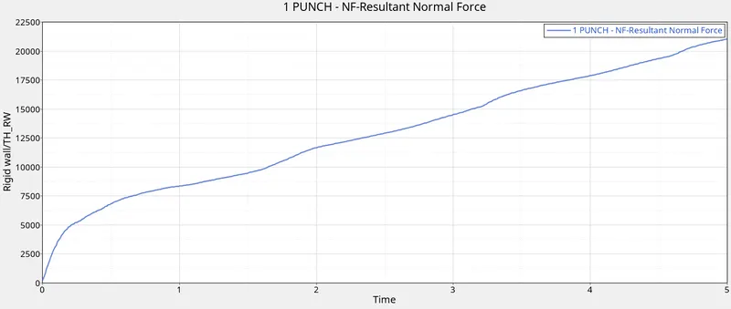
In this case, the Eps_max value was deleted. This implies that failure plastic strain can take infinite value. Hence the stress will keep increasing and no failure will be generated. This value can be changed in the material card. In this case, the simulation shows the deformation of the plate which exceeds the yield stress means the deformation is permanent and form fracture. The time step varies smoothly increases and also the normal force of the punch reaches the max point. The max von mises stress is 424.7 N/mm2 which is near to max stress and the energy error is 0.8% means the model is consistent for this case. The energy dissipation is almost linear overall simulation.
Case 5 :- Law1
- In this case the material card was changed to Law 1, which is the elastic material. It defines an isotropic linear elastic material. This material law is used to model purely elastic materials. The main cons of this law is not used for large deformation because it can regain to its original shape.
- In this case we have to change the material card as M1_ELAST and need to run the simulation with law 1.
- The changes in material card is shown in below image.
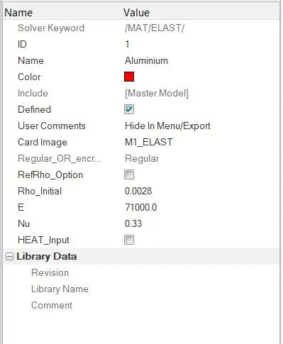
- After changing the parameters run the simulation with same steps to be carried as per previous case. The simulation is shown in GIF below. Plot the graphs of energies and punch resultant normal force.
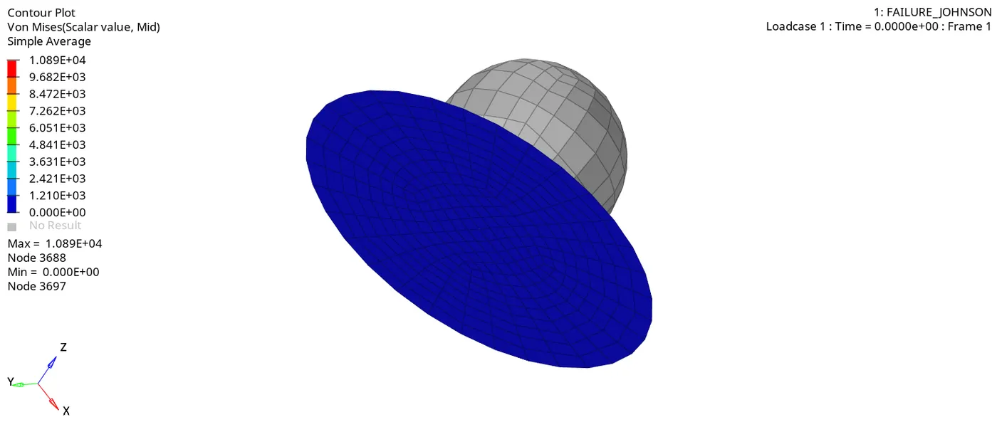
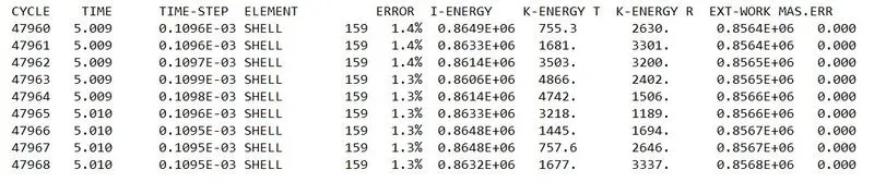
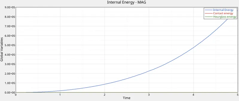
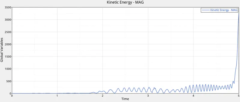
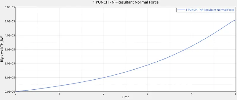
The above figure shows the simulation of Law1_Elastic. Here, the material is used as aluminium and the properties are rho = 0.0028 g/mm3 , E = 71000 N/mm2 , Nu = 0.33. The run time of the simulation is 5.01 ms and the Tfreq = 1. The simulation is based on the impact of Rigid ball on the circular plate, in this case the energy dissipation is 800 KJ and varies smoothly. There is no hourglass energy formed because the number of integrations point as 5 and the energy error is 1.3%. The max von mises stress formed is 10.89 KN/mm2 which is max when compared to all the cases, which defines the yield criteria and fracture point. The Kinetic energy is varying smoothly because of elasticity there is no failure will cause to the model.
Case 6 :- LAW27_Elasto_Plastic_Brittle
- This law combines an isotropic elasto-plastic Johnson-Cook material model with an orthotropic brittle failure model. Material damage is accounted for prior to failure. Failure and damage occur only in tension. This law is applicable only for shells.
In this model, the material behaves as a linear-elastic material when the equivalent stress is lower than the plastic yield stress. For higher stress values, the material behavior is plastic and the stress is calculated as,
σ=(a+bεpn)(1+clnε/ε0)
Where,
εp - Plastic strain
ε_dot - Strain rate
The plasticity hardening exponent, n must be less than 1.
Damage and rupture defined with 4 parameters for each principal direction:
- et = Strain at the beginning of tensile failure
- em = Maximum tensile strain at which the stress in the element is set to a value dependent on dmax1
- dmax = Maximum tensile damage factor
- ef = Maximum tensile strain for element deletion
- In this case, the file named Law27_0000.rad was opened and the shell properties were changed to recommended values. Also, the given file had different values defined for Eps_max. The material model is law27, which is elasto plastic material with brittle failure.
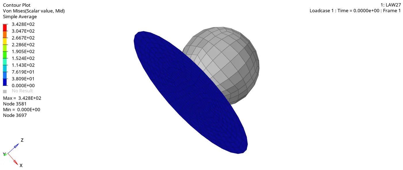
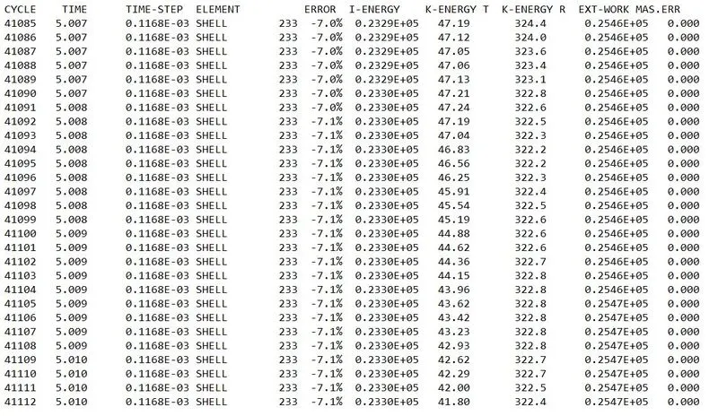
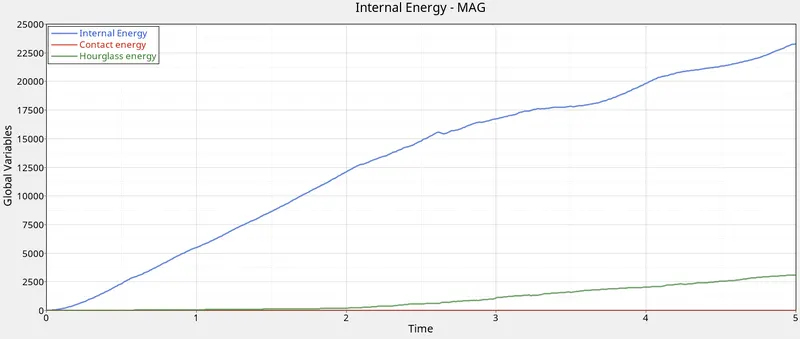
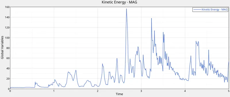
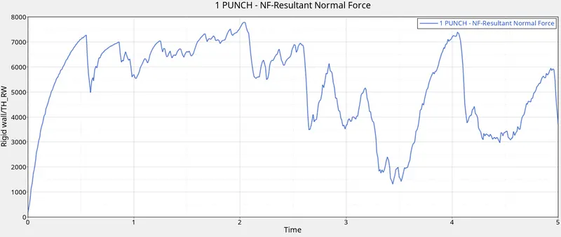
- In this case, the deformation of the plate is smooth after that elements are cracked and deleted at the critical point because of brittle material. At that point, the time step varies rapidly and also the normal force of the punch reaches the max point. The max von mises stress is 342 N/mm2 which exceeds the yield stress and the energy error is -7.1% means the model is not consistent for this case. The energy dissipation is more and varies almost linear overall the simulation. The hourglass is varying after the elements crack therefore the energy error is maximum. The Kinetic energy is varied peak at the time 2.5 ms because the object fails (element deletion) at a short time because of Brittle material when reaches to yield point.
Case 7 :- LAW 36
- This law models an isotropic elasto-plastic material using user-defined functions for the work-hardening portion of the stress-strain curve (for example, stress vs. plastic strain) for different strain rates.
- After changing the parameters run the simulation with same steps to be carried as per previous case. The simulation is shown in GIF below. Plot the graphs of energies and punch resultant normal force.
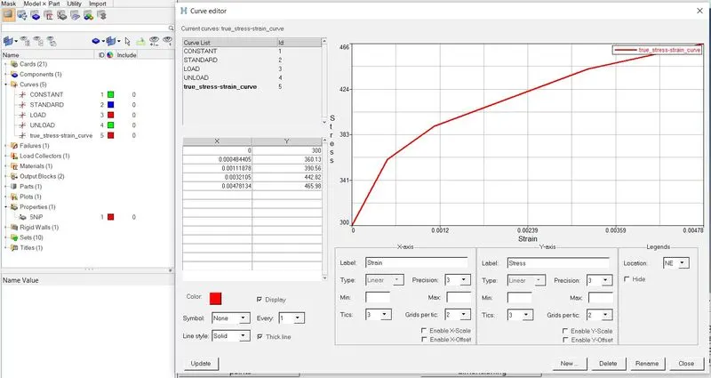
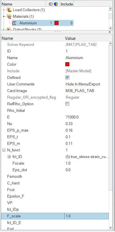
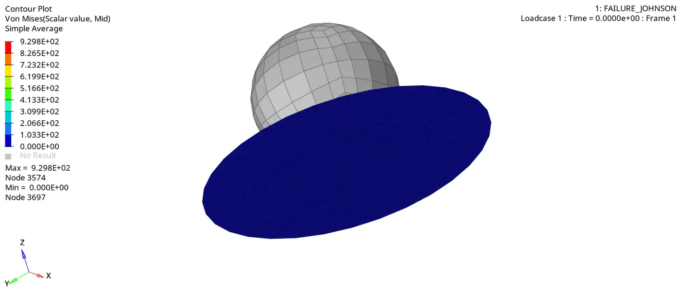
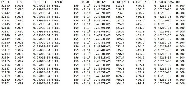
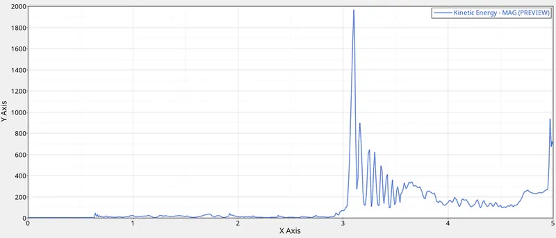
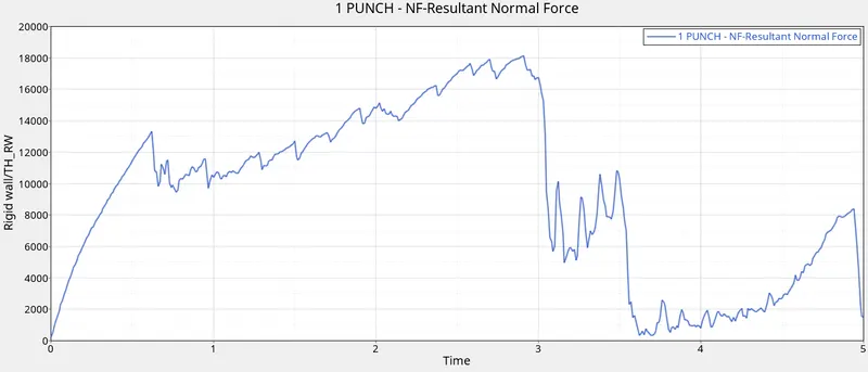
3.In this case, the material properties are shown in above fig which defines the eps_p_max, eps_t, eps_m. The simulation shows upto 3 ms the deformation of the plate is smooth after that elements are cracked and deleted at the critical point. At that point, the time step as suddenly increases and also the normal force of the punch reaches the max point. The max von mises stress is 930 N/mm2 and the energy error is -1.4% . The energy dissipation is almost linear upto 3ms and varies randomly because of the element crack and deletion. The Kinetic energy is varied peak at the time 3 ms in which the element deletion is occurred, due to remaining elements present in the plate the energy dissipation is remain constant and decrease in the kinetic energy
Results :-
Comparison of no. of cycles, energy errors, mass errors and simulation time are given in below table.
|
Case no. |
Particulars |
No. of cycles |
Energy Error (%) |
Mass Error (%) |
Simulation time (S) |
|
Case1 |
Law2_epsmax_failure |
49380 |
0.8 |
0 |
175.49 |
|
Case2 |
Law2_epmax_crack |
49217 |
4.1 |
0 |
169.73 |
|
Case3 |
Law2_epmax_nofail |
49408 |
0.8 |
0 |
157.74 |
|
Case4 |
Law2 |
48767 |
3 |
0 |
150.26 |
|
Case5 |
Law1 |
47969 |
1.3 |
0 |
163.13 |
|
Case6 |
LAW27_Elasto_Plastic_Brittle |
41113 |
-7.1 |
0 |
171.51 |
|
Case7 |
LAW 36 |
52189 |
-1.1 |
0 |
176.34 |
- The number of cycles for the law 2 & 27 is almost equal. Law 1 has the lowest number of cycles since no element is deleted & law 36 has the largest number of cycles.
- Mass error and energy error also were with limits due to the recommended shell formulations.
- The Simulation time for law 36 is the highest & least for case 4.
- Hourglass energy remained almost zero during all the cases.
Conclusion :-
All the cases are simulated and compared with no. of cycles, energy and mass errors and simulation time. Based on all the results, following cases would represent the on-field
scenario.
- Case 1 and 6 are more realistic on field scenarios due to failure card and build in strain failures covering normal stresses and shear stresses. Case 2 with its crack propagation feature would be useful in small crack observations.
- Case 7 would be really useful for simulating, if test data is available for different strain rates would help in crash-based analysis giving more realistic results.