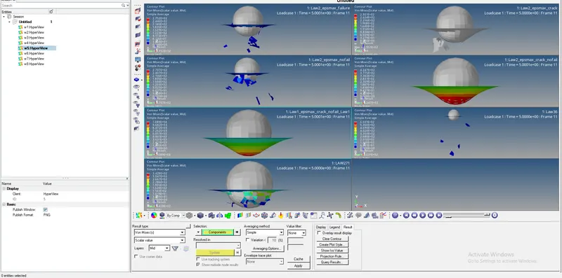
Assignment 4-RADIOSS Material Laws Challenge
Objective:
To perform the simulation as per the cases given below and compare 7 cases in a tabulated format based on:
1. The Total number of cycles, Energy error, mass error, and simulation time.
2. Notice the animation of all 5 and describe the animations in brief based on whether the elements are being deleted or cracked.
3. Plot energies and notice any difference.
4. Based on all the results, which case would represent the on-field scenario.
5. Prepare a ppt/Docx and list down case by case results and your conclusion as to why the failure happened.
Radioss Cards/Material Laws
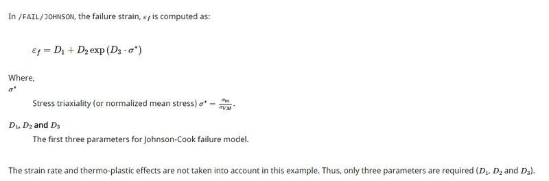
/FAIL/JOHNSON : Describes the failure criteria by Johnson-Cook failure model.
Shell failure flag. Ifail_sh
- = 0 (Default)Shell is not deleted.
- = 1 Shell is deleted or cracked, if there is one layer in the failure zone.
- = 2 The layer stress tensor is set to zero, if this layer is in the failure zone, and the shell is deleted or cracked, only if all layers are in the failure zone.
- = 3 Shell is deleted only when membrane strain reaches criterion.
- = 4 Criterion is calculated but element is not deleted.
If Ixfem =0: failure - element deleted.
If Ixfem =1: failure - element cracked.
- ***XFEM formulation (Ixfem=1) is only compatible with Belytchko (Ishell=1 or 2), Ishell=3 or 4 and QEPH (Ishell=24) shell elements. If XFEM flag is activated (Ixfem=1), the failure criteria will lead to element cracking instead of element or layer deletion.
-
Two XFEM options are available: mono-layer and multi-layer. The XFEM option depends on the property type associated to the failure criterion applied to the material identifier:
- If /PROP/SHELL (TYPE1) is used, then mono-layer XFEM will be applied.
In this case, the whole element thickness is considered as a single layer. The failure criterion is calculated in each integration point, but only one crack can appear in this element. This approach is compatible with all values of the shell flag (Ifail_sh=1 or 2). The crack direction is determined by the principal constraints in the last failed integration point.
- If /PROP/SH_SANDW (TYPE11) is used, then multi-layer XFEM will be applied.
In this case, each integration point over thickness is considered as a distinct layer. The failure criterion is calculated separately and the crack direction may be different in each layer. Crack direction in each layer will independently propagate from one element to another. Multi-layer XFEM is not compatible with Ifail_sh=1. Its value will be automatically set to Ifail_sh=2 in this case.
- If /PROP/TYPE51 is used, then multi-layer XFEM will be applied and the separate cracks may appear in each layer and propagate independently from one element to another. Thus, crack directions and patterns will be different in each layer. The failure criterion is calculated separately in each integration point and crack will propagate when all the integration points fail within a layer. Multi-layer XFEM is not compatible with Ifail_sh=1. Its value will be automatically set to Ifail_sh=2.
Warning: Mono-layer and multi-layer XFEM formulations cannot be mixed in the same model, yet. The choice between them must be made for the whole model.***
- If /PROP/SHELL (TYPE1) is used, then mono-layer XFEM will be applied.
Dadv Criterion for crack advancement.
Only active, if Ixfem=1.(Real, between 0 and 1)
Default = 0.5, if fct_IDadv is not defined (for backward compatibility)
Default = 1.0, if fct_IDadv is defined
***When the Ixfem option is used, a supplementary criterion is available for crack advancement, which may be different from the one used for the failure initialization. It will be used for elements with an existing crack tip at their border. If fct_IDadv is defined, Dadv is used as a scale factor for this function to obtain the advancement failure value. If fct_IDadv is not defined, the original FLD diagram (fct_ID) is used with the Dadv scale factor to obtain this value.***
XFEM flag (for /PROP/SHELL, /PROP/SH_SANDW, and /PROP/TYPE51 properties only).
- = 1 XFEM formulation.
- = 0 (Default)Without XFEM.
- ***XFEM formulation (Ixfem=1) is only compatible with Belytchko (Ishell=1 or 2), Ishell=3 or 4 and QEPH (Ishell=24) shell elements. If XFEM flag is activated (Ixfem=1), the failure criteria will lead to element cracking instead of element or layer deletion.
-
Two XFEM options are available: mono-layer and multi-layer. The XFEM option depends on the property type associated to the failure criterion applied to the material identifier:
- If /PROP/SHELL (TYPE1) is used, then mono-layer XFEM will be applied.
In this case, the whole element thickness is considered as a single layer. The failure criterion is calculated in each integration point, but only one crack can appear in this element. This approach is compatible with all values of the shell flag (Ifail_sh=1 or 2). The crack direction is determined by the principal constraints in the last failed integration point.
- If /PROP/SH_SANDW (TYPE11) is used, then multi-layer XFEM will be applied.
In this case, each integration point over thickness is considered as a distinct layer. The failure criterion is calculated separately and the crack direction may be different in each layer. Crack direction in each layer will independently propagate from one element to another. Multi-layer XFEM is not compatible with Ifail_sh=1. Its value will be automatically set to Ifail_sh=2 in this case.
- If /PROP/TYPE51 is used, then multi-layer XFEM will be applied and the separate cracks may appear in each layer and propagate independently from one element to another. Thus, crack directions and patterns will be different in each layer. The failure criterion is calculated separately in each integration point and crack will propagate when all the integration points fail within a layer. Multi-layer XFEM is not compatible with Ifail_sh=1. Its value will be automatically set to Ifail_sh=2.
Warning: Mono-layer and multi-layer XFEM formulations cannot be mixed in the same model, yet. The choice between them must be made for the whole model.***
- If /PROP/SHELL (TYPE1) is used, then mono-layer XFEM will be applied.
/MAT/LAW1 (ELAST) : Defines an isotropic, linear elastic material using Hooke's law. This law represents a linear relationship between stress and strain. It is available for truss, beam (type 3 only), shell and solid elements.
/MAT/LAW2 (PLAS_JOHNS) : Represents an isotropic elasto-plastic material using the Johnson-Cook material model. This model expresses material stress as a function of strain, strain rate and temperature. A built-in failure criterion based on the maximum plastic strain is available.
/MAT/LAW27 (PLAS_BRIT) : Combines an isotropic elasto-plastic Johnson-Cook material model with an orthotropic brittle failure model. Material damage is accounted for prior to failure. Failure and damage occur only in tension. This law is applicable only for shells.
/MAT/LAW36 (PLAS_TAB) : Models an isotropic elasto-plastic material using user-defined functions for the work-hardening portion of the stress-strain curve (for example, plastic strain vs. stress) for different strain rates.
LAW2 and Johnson-Cook Failure Model :
The elasto-plastic behavior of the material is defined using the Johnson-Cook law (/MAT/LAW2 (PLAS_JOHNS)), with damage (maximum plastic strain, ε maxp). The failure model /FAIL/JOHNSON is independent from the material law and the hardening model.
The Johnson-Cook failure model is defined using /FAIL/JOHNSON in the input deck. The model uses accumulative damage to compute failure.
COMPARISON:
1. The Total number of cycles, Energy error, mass error, and simulation time.
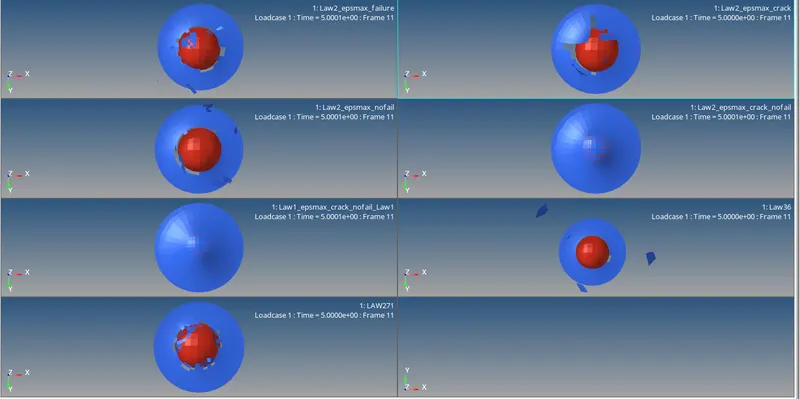
2. Notice the animation of all 5 and describe the animations in brief based on whether the elements are being deleted or cracked.
| Cases |
Jhonson failure card. Ifail_sh= Dadv= Ixfem= |
failure plastic strain (EPS_p_max) |
Material Law number |
Total Number of Cycles |
Energy Error |
Simulation Time/Elapsed time. |
Condition of Elements |
Comments for Q1-5 |
|
1 |
2 0 0 |
0.151 |
LAW2 (PLAS_JOHNS) |
49380 |
-0.6% to 1.3% |
0:03:44 |
The shell is deleted for failure in all integration points or layers. | Failure is seen earlier as compared to Case 2.This is reflected in superimposed graph of resultant forces and total energy. Fig 4 |
|
2 |
1 1 1 |
0.151 |
LAW2 (PLAS_JOHNS) |
49217 |
-1.1% to 4.5% |
0:01:49 |
First the failure criteria leads to element cracking instead of element/ layer deletion. Then solid element is deleted, for failure in one integration point. |
XFEM flag is activated (Ixfem=1), the failure criteria will lead to element cracking instead of element or layer deletion. |
|
3 |
0 0 0 |
0.151 |
LAW2 (PLAS_JOHNS) |
49408 |
-0.6% to 1.2% |
0:01:45 |
Deleted and shattered | The only difference that lies in this and 1st case is the failure criteria. Here as soon as EPS_p_max value is reached the failure occurs. Fig 5 |
|
4 |
0 0 0 |
0 |
LAW2 (PLAS_JOHNS) |
48737 |
-0.6% to 3.0% |
0:01:40 |
Deformed due to high Default elastic Strain value=10^30 |
Notice material is undergoing plastic deformation. There is plastic strain induced. Fig 6 |
|
5 |
0 0 0 |
0 |
LAW1 (ELAST) |
47969 |
-0.6% to 4.0% |
0:01:37 |
Deformed due to Elastic material law |
This law represents a linear relationship between stress and strain. So plastic strain is absent. Fig 6 |
|
6 |
0 0 0 |
0.16 |
LAW36 (PLAS_TAB) |
53144 |
-1.8% to 0.5% |
0:01:43 |
Deleted Suddenly |
Once εp (plastic strain) reaches ε max, in one integration point, the element is deleted. Elements are deleted suddenly and you see a single sudden spike in kinetic energy. Fig1 and 7. |
|
7 |
0 0 0 |
Absent for brittle behaviour |
LAW27 (PLAS_BRIT) |
41113 |
-7.1% to 0.5% |
0:01:18 |
Deleted abruptly | Brittle behaviour of elements is displayed in kinetic energy graph where multiple spikes are seen resulting from brittle elements. Fig 8 and fig 9. |
Fig 1
3. Plot energies and notice any difference.
Fig 2
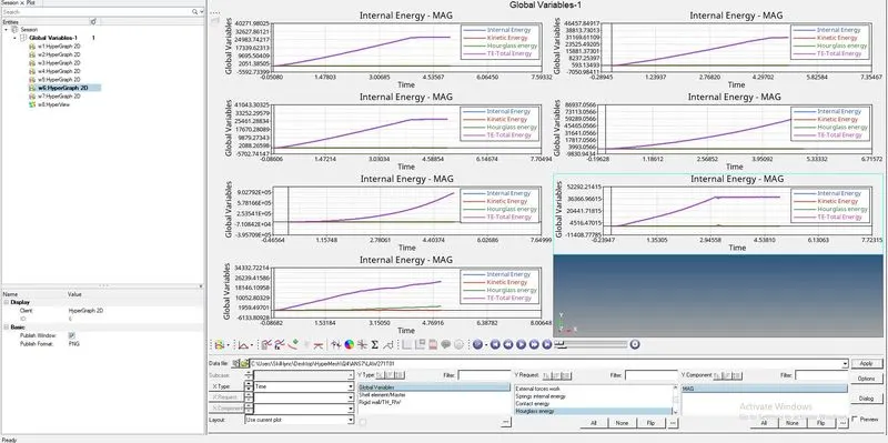
Fig 3
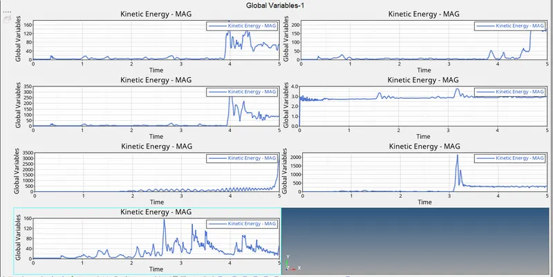
Fig 4
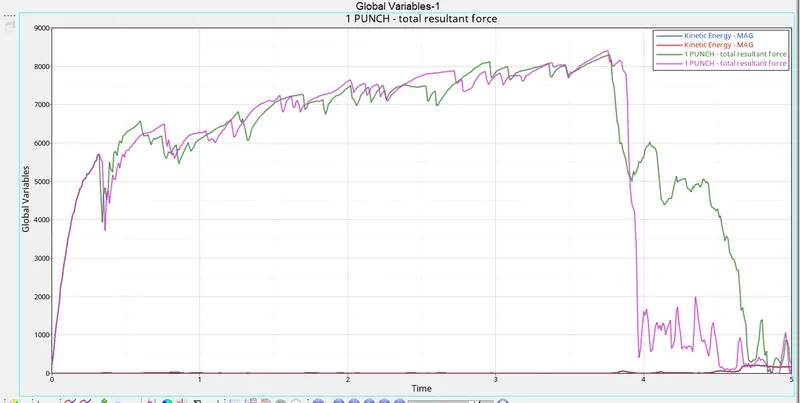
Fig 5
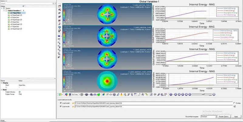
Fig 6
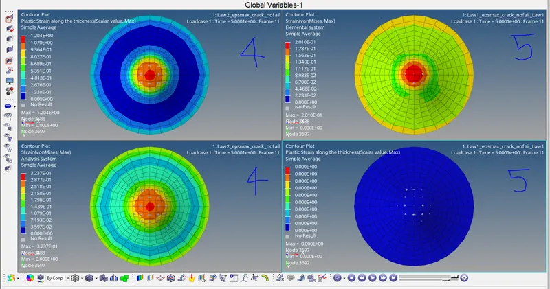
Fig 7
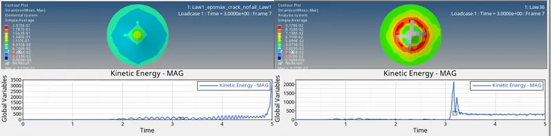
Fig 8

Fig 9
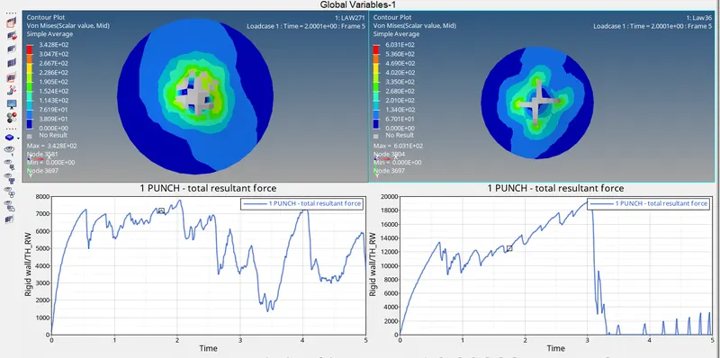
4. Based on all the results, which case would represent the on-field scenario.