COMPARISON OF MATERIAL LAW WITH DIFFERENT PARAMETERS DURING EXPLICIT ANALYSIS
AIM:-To understand the material laws in hypermesh and its behavior when undergoes analysis
PROCEDURE:-
- Importing the 000.rad file to hypermesh
- Changing the material laws
- Observing the changes in the models and graphs while doing analysis
- And then we need to conclude the results
IMPORTING FILE:-
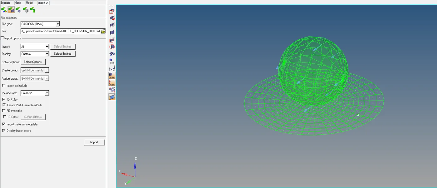
- Open HyperWorks and import solver deck and select 000.rad and select open
THEORY:-
There are different types of laws concerning the material
Law 1 – Elastic
Law 2 – Johnson-Cook
Law 25 – Composite
Law 27 – Elastic-Plastic Brittle
Law 28 – Honeycomb
Law 36 – Elastic-Plastic Tabulated
Law 42 – Ogden (Hyperelastic)
Law 69 – Ogden & Mooney-Rivlin (Hyperelastic)
Law 70 – Foam
LAW 1:-
- Which is used majorly for elastic materials it is worth up to the material doesn't cross the yield point we get the accurate result
- If it crosses the yield point then the value that we get is the garbage value
- It is used only for an elastic material, we give three parameters to find material stiffness like density, young's modulus, Poisson's ratio
Note:- except law1 all are used for iso plastic materials
LAW 2:-
- This model expresses material stress as a function of strain, strain rate, and temperature.
- It has built-in failure criteria based on the maximum plastic strain is available
- If the material is not temperature or strain rate sensitive, then: Calculate true stress and strain from engineering values from the tensile test
σy ≅ Sy σu = Su(1+ EU) εu = ln(1+ EU)
- To calculate true strain we need to consider the rule that engineering stress is equal to true stress up to yield point
- By using engineering stress we will calculate the value of true stress and true strain
- The values of a are to plot the graph of the stress-strain curve up to yield point and b and n are need to take up the job to plot the graph up to necking
- Sig max is nothing but the ultimate strength value the graph between yield and ultimate strength is taken care of by hardening modulus and hardening component
- Tangent modulus will be straight for the john's cook law
- As to calculate the tangent modulus after crossing the yield point the next point is drawn to tangent b/w two-point and the slope is found and then the slope is interpolated it will continue up to the last point
- While doing the analysis the heat generated will be minimum so that we need to take temperature as constantly we get the formula as

- We need a specific strain rate to control the failure of analysis
- It is basically for non-linear materials
- As you see the graph is not started from zero and the graph started from the yield point to calculate plastic strain by strain rate
- As for some material we unable to calculate the yield point so we need to take the strain rate as 0.2-0.3
- As we changing then N we get different graph majorly n=0 for brittle and n=1 for plastics we will get the stress value
- In software Iflag=1 automatically determines Johnson-Cook parameters based on:
• Yield stress (SIG_y)
• Ultimate tensile engineering stress (UTS)
• Engineering strain ( EPS_UTS ) at necking point - we can control the failure rate we need to specify the values of D1, D2, D3 are stress value at three directions linear, lateral, normal to the object
LAW 36
- This law is majorly used in the industries
- Because john's cook law has a lot of approximations so majorly law36 is preferred.
- Here we need to stress-strain curve to the material with respective the tabulated graph the software interpolate with values and get the result
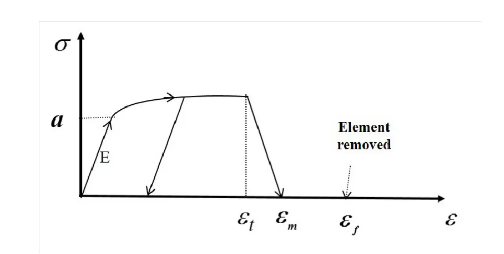
εf is the tensile failure strain value for element deletion
εm is the end of the tensile damage. The stress value is null but the element is
not deleted
εp max is the maximum plastic strain for element deletion for any loading
εt Tensile failure strain at which stress starts to reduce.
| Fsmooth | Smooth strain rate option flag. |
CASE 1:-
- Run the model as it was given
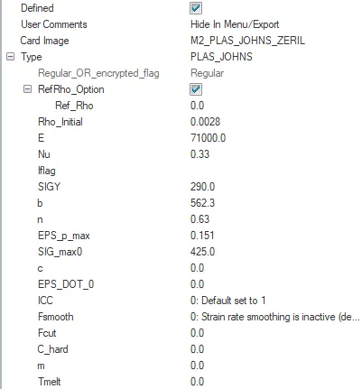
Properties of the given file
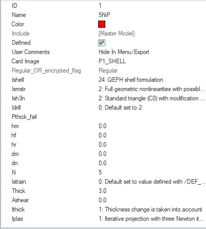
Material properties of the given file
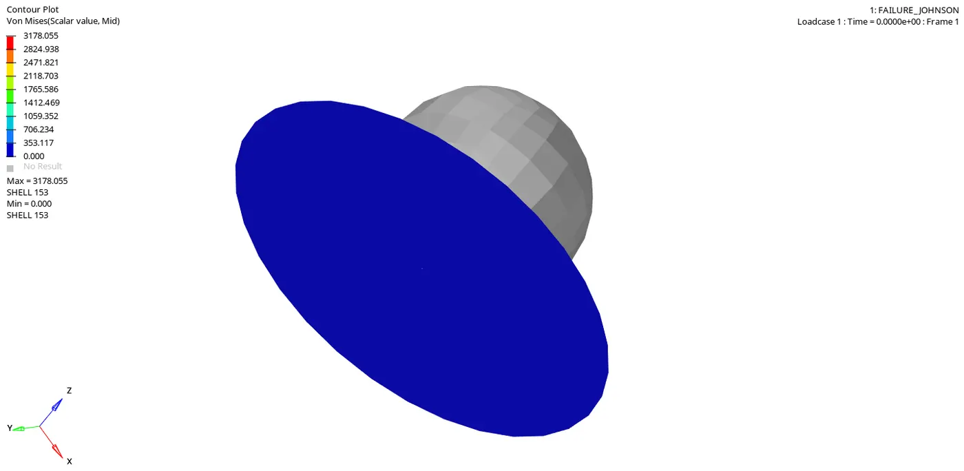
Failure of the given file

Engine runtime = 5..01ms
Animation frequency = 0.5
RESULT OF ANALYSIS
- ENERGY ERROR AND MASS ERROR
CYCLE TIME TIME-STEP ELEMENT ERROR I-ENERGY K-ENERGY T K-ENERGY R EXT-WORK MAS.ERR
49369 5.009 0.1011E-03 SHELL 159 0.8% 0.2730E+05 68.37 61.53 0.2721E+05 0.000
49370 5.009 0.1011E-03 SHELL 159 0.8% 0.2730E+05 68.28 61.62 0.2721E+05 0.000
49371 5.009 0.1011E-03 SHELL 159 0.8% 0.2730E+05 68.21 61.71 0.2721E+05 0.000
49372 5.009 0.1011E-03 SHELL 159 0.8% 0.2730E+05 68.14 61.81 0.2721E+05 0.000
49373 5.009 0.1011E-03 SHELL 159 0.8% 0.2730E+05 68.07 61.90 0.2721E+05 0.000
49374 5.009 0.1011E-03 SHELL 159 0.8% 0.2730E+05 68.02 62.00 0.2721E+05 0.000
49375 5.010 0.1011E-03 SHELL 159 0.8% 0.2730E+05 67.97 62.09 0.2721E+05 0.000
49376 5.010 0.1011E-03 SHELL 159 0.8% 0.2730E+05 67.92 62.17 0.2721E+05 0.000
49377 5.010 0.1011E-03 SHELL 159 0.8% 0.2730E+05 67.88 62.25 0.2721E+05 0.000
49378 5.010 0.1011E-03 SHELL 159 0.8% 0.2730E+05 67.85 62.32 0.2721E+05 0.000
49379 5.010 0.1011E-03 SHELL 159 0.8% 0.2730E+05 67.81 62.38 0.2721E+05 0.000
MAXIMUM TIME STEP. . . . . . . . . . . . . . . . 0.1000000E+31
TOTAL NUMBER OF CYCLES : 49380
STARTER+ENGINE RUNTIME = 55.57s (00:00:55)
- As we can see that energy error is less than 5% and mass error is zero that mean no mass is added to reduce the time step
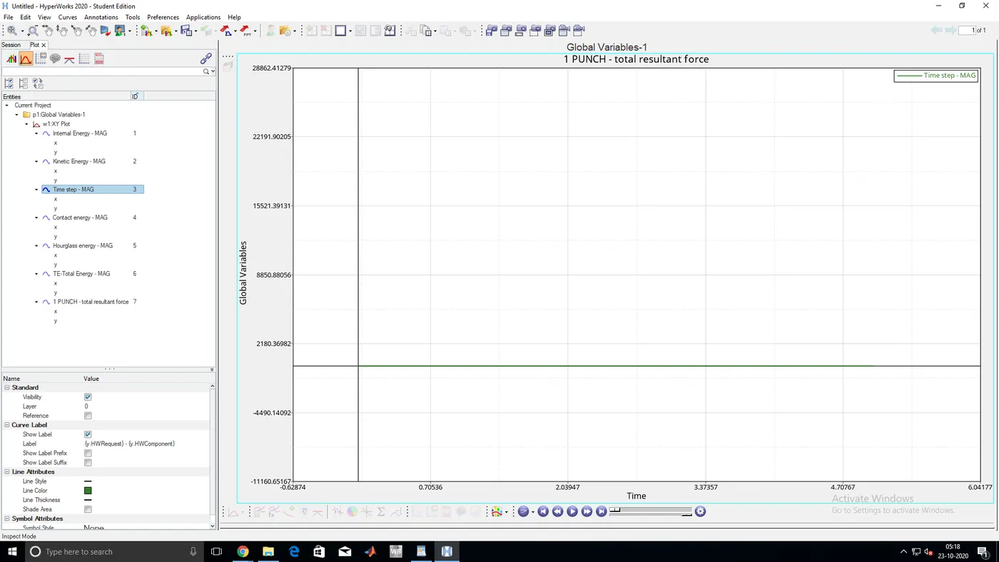
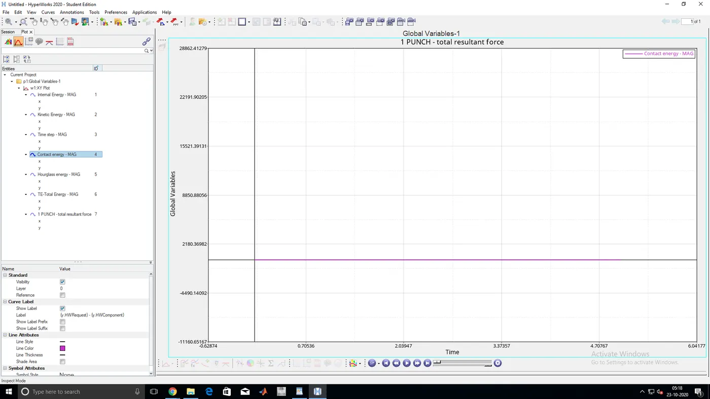
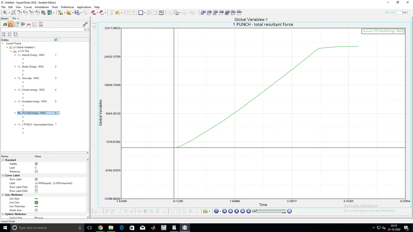
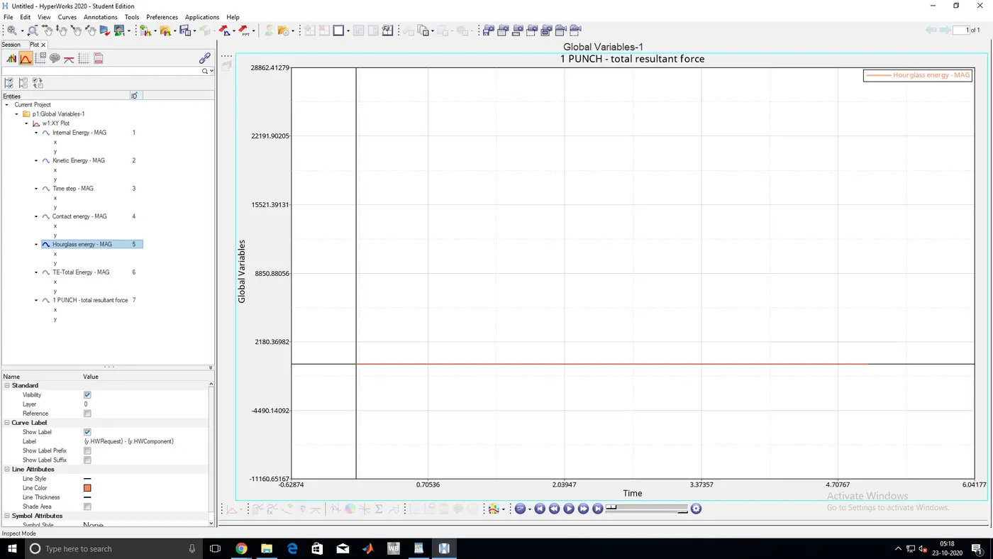
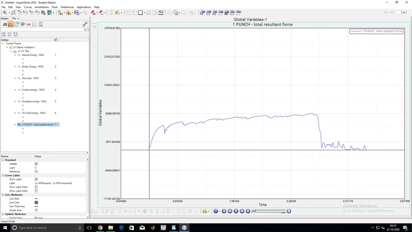
- TOTAL ENERGY,INTERNAL ENERGY,KINETIC ENERGY,TIME STEP,CONTACT ENERGY,HOURGLASS ENERGY GRAPHS
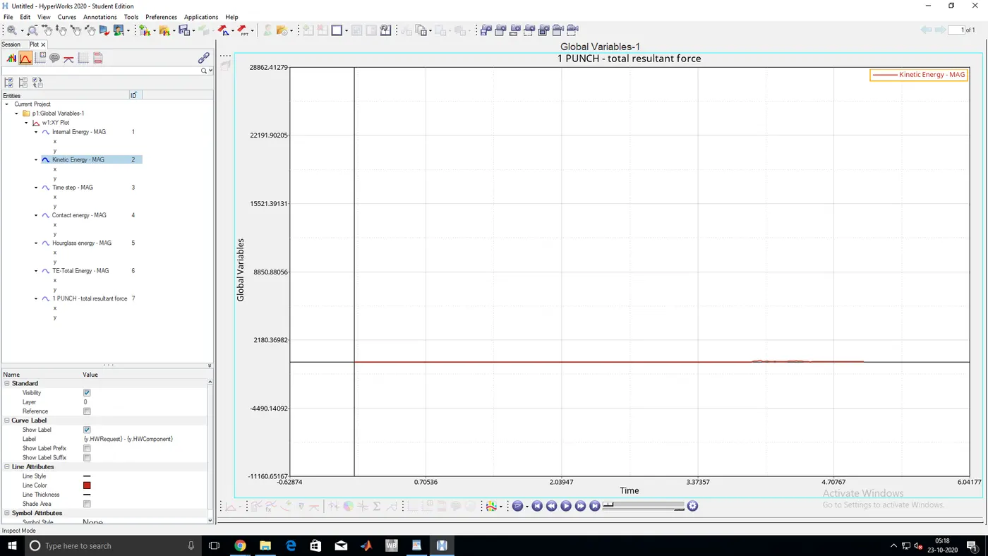
- As we see the kinetic energy is constant but at the end the deviation is occurred due to rupture of material
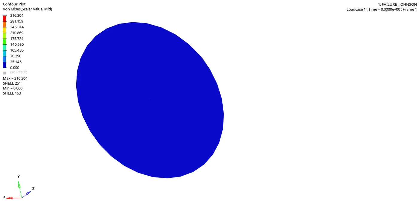
ANIMATION FILE
CASE 2:-
- Take above file with same properties and change values of failure card
ifail_sh =1,Dadv =1,Ixfem =1
- Run the model
Engine runtime = 5.01ms
Animation frequency = 0.5
RESULT:
- ENERGY ERROR AND MASS ERROR
CYCLE TIME TIME-STEP ELEMENT ERROR I-ENERGY K-ENERGY T K-ENERGY R EXT-WORK MAS.ERR
49207 5.009 0.1069E-03 SHELL 210 4.1% 0.3080E+05 147.4 60.72 0.2980E+05 0.000
49208 5.009 0.1069E-03 SHELL 210 4.1% 0.3080E+05 146.9 60.78 0.2980E+05 0.000
49209 5.009 0.1069E-03 SHELL 210 4.1% 0.3081E+05 146.4 60.84 0.2980E+05 0.000
49210 5.009 0.1069E-03 SHELL 210 4.1% 0.3081E+05 145.9 60.90 0.2980E+05 0.000
49211 5.009 0.1069E-03 SHELL 210 4.1% 0.3081E+05 145.3 60.96 0.2980E+05 0.000
49212 5.010 0.1069E-03 SHELL 210 4.1% 0.3081E+05 144.7 61.03 0.2980E+05 0.000
49213 5.010 0.1069E-03 SHELL 210 4.1% 0.3081E+05 144.1 61.10 0.2980E+05 0.000
49214 5.010 0.1069E-03 SHELL 210 4.1% 0.3081E+05 143.4 61.19 0.2980E+05 0.000
49215 5.010 0.1069E-03 SHELL 210 4.1% 0.3082E+05 142.6 61.29 0.2980E+05 0.000
49216 5.010 0.1069E-03 SHELL 210 4.1% 0.3082E+05 141.9 61.40 0.2980E+05 0.000
MAXIMUM TIME STEP. . . . . . . . . . . . . . . . 0.1000000E+31
TOTAL NUMBER OF CYCLES: 49217
STARTER+ENGINE RUNTIME = 92.88s (00:01:32)
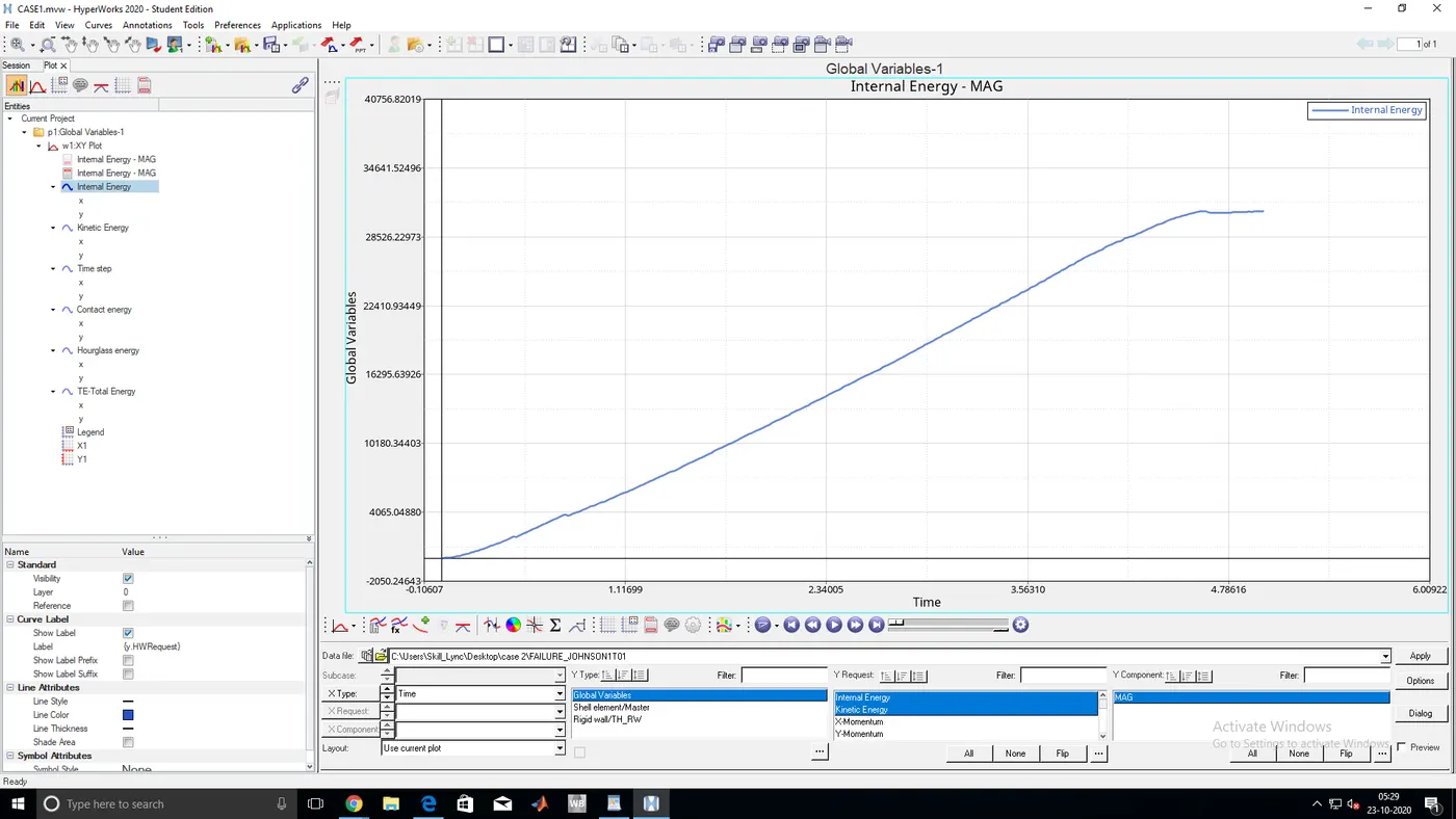
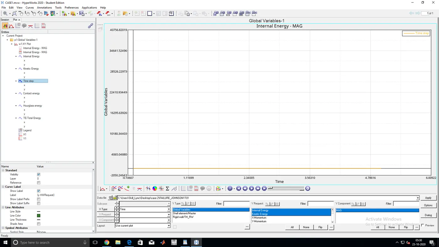
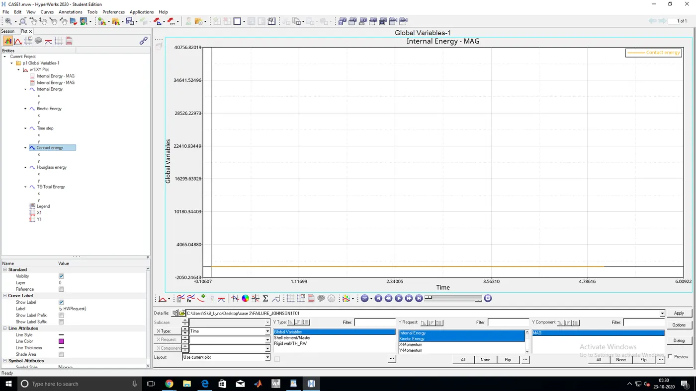
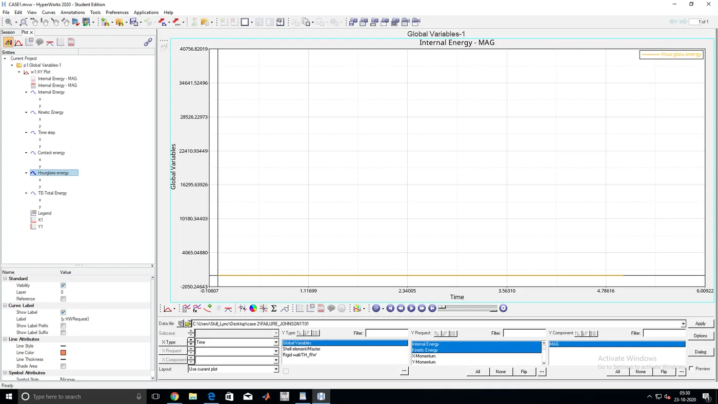
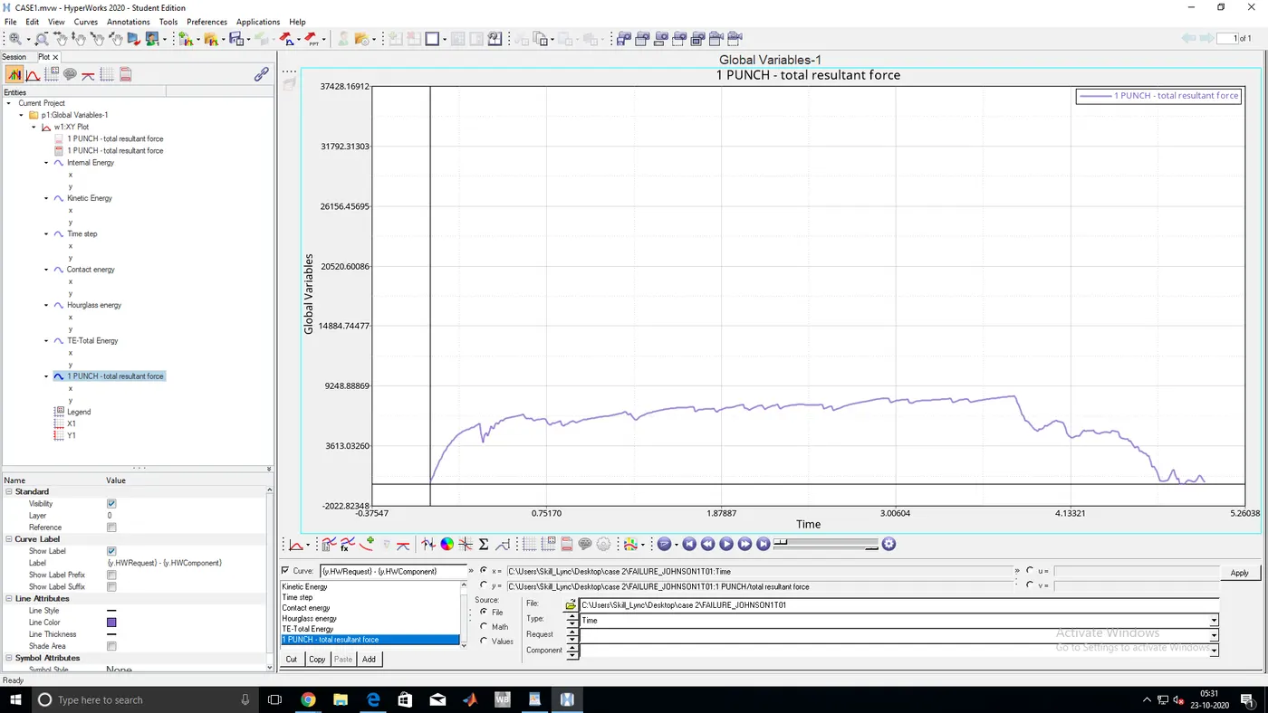
- TOTAL ENERGY,INTERNAL ENERGY,KINETIC ENERGY,TIME STEP,CONTACT ENERGY,HOURGLASS ENERGY GRAPHS
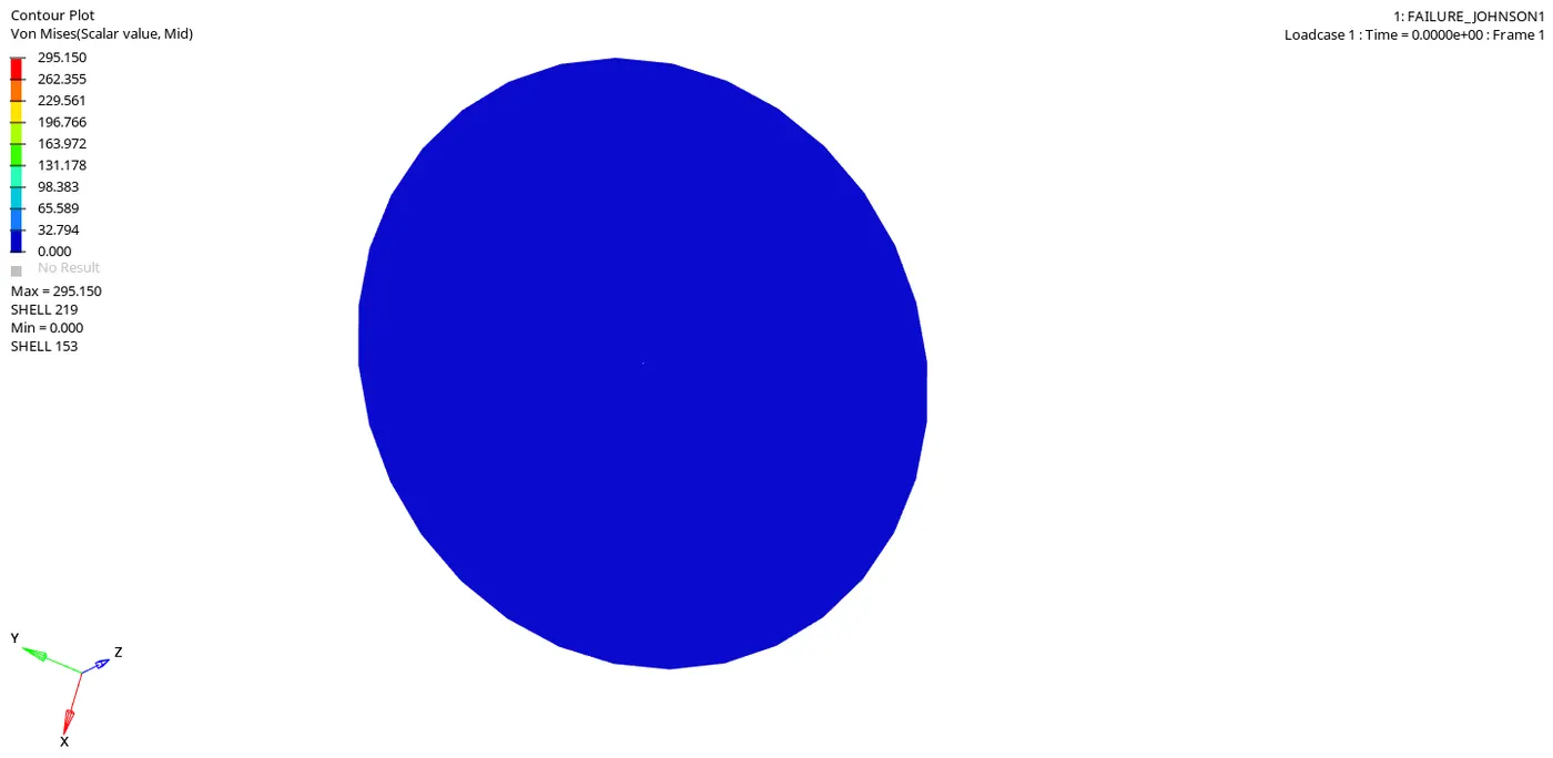
CASE 3:
- Delete the failure card of the above-given file and run the stimulation
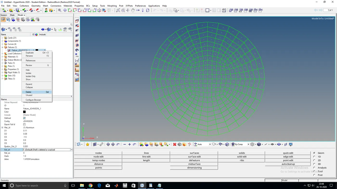
- ENERGY ERROR AND MASS ERROR
CYCLE TIME TIME-STEP ELEMENT ERROR I-ENERGY K-ENERGY T K-ENERGY R EXT-WORK MAS.ERR
49400 5.009 0.1010E-03 SHELL 159 0.8% 0.2744E+05 83.56 61.33 0.2736E+05 0.000
49401 5.009 0.1010E-03 SHELL 159 0.8% 0.2744E+05 84.22 61.47 0.2736E+05 0.000
49402 5.009 0.1010E-03 SHELL 159 0.8% 0.2744E+05 84.85 61.60 0.2736E+05 0.000
49403 5.010 0.1010E-03 SHELL 159 0.8% 0.2744E+05 85.45 61.72 0.2736E+05 0.000
49404 5.010 0.1010E-03 SHELL 159 0.8% 0.2744E+05 85.98 61.83 0.2736E+05 0.000
49405 5.010 0.1010E-03 SHELL 159 0.8% 0.2744E+05 86.43 61.93 0.2736E+05 0.000
49406 5.010 0.1010E-03 SHELL 159 0.8% 0.2744E+05 86.80 62.02 0.2736E+05 0.000
49407 5.010 0.1010E-03 SHELL 159 0.8% 0.2744E+05 87.08 62.10 0.2736E+05 0.000
TOTAL NUMBER OF CYCLES: 49408
STARTER+ENGINE RUNTIME = 52.42s (00:00:52)
MAXIMUM TIME STEP. . . . . . . . . . . . . . . . 0.1000000E+31
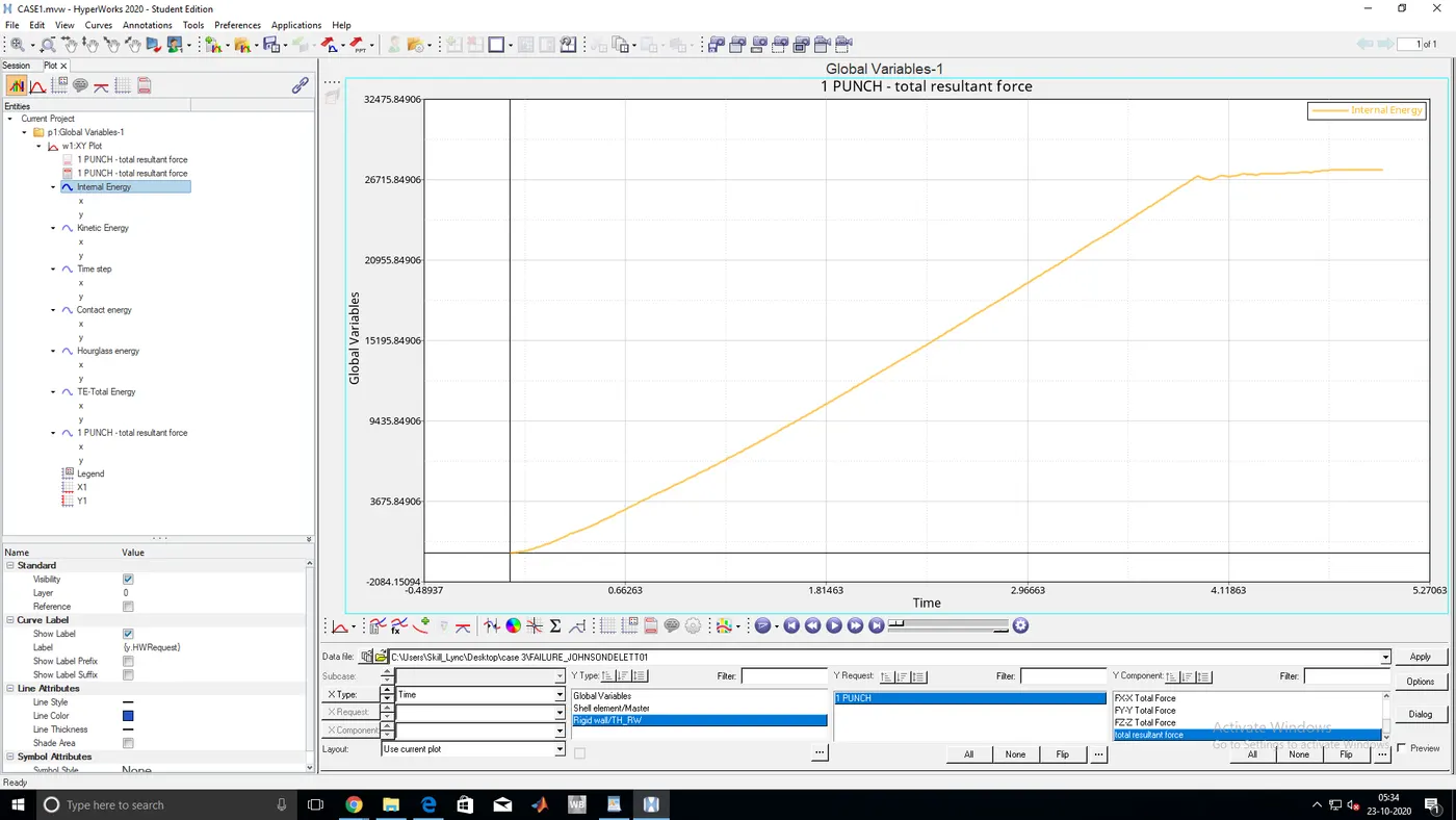
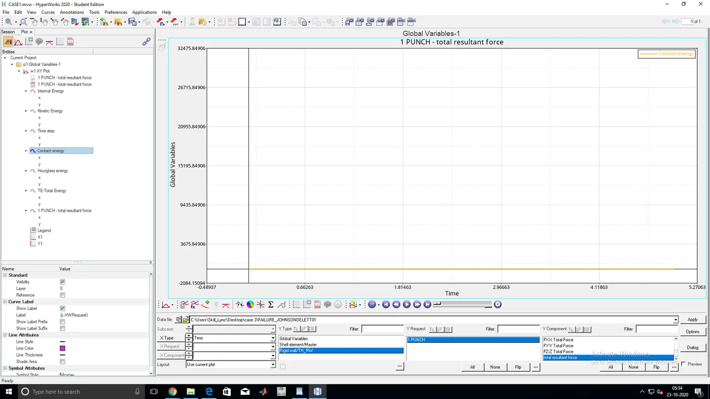
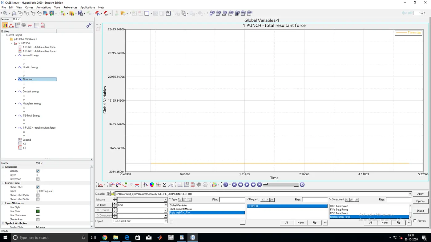
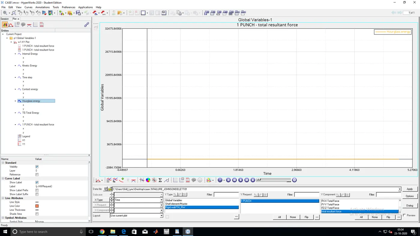
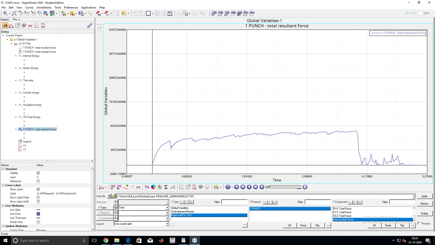
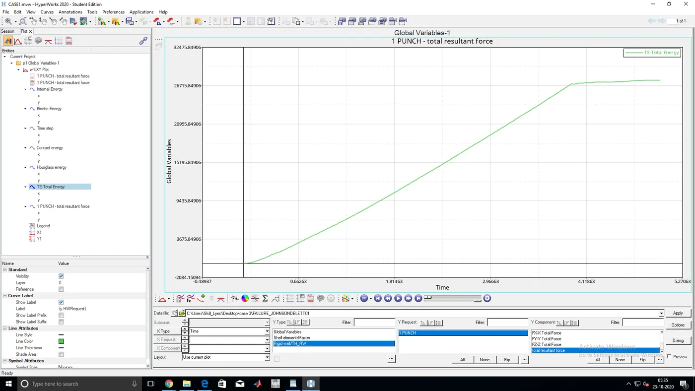
- TOTAL ENERGY,INTERNAL ENERGY,KINETIC ENERGY,TIME STEP,CONTACT ENERGY,HOURGLASS ENERGY GRAPHS
CASE 4:
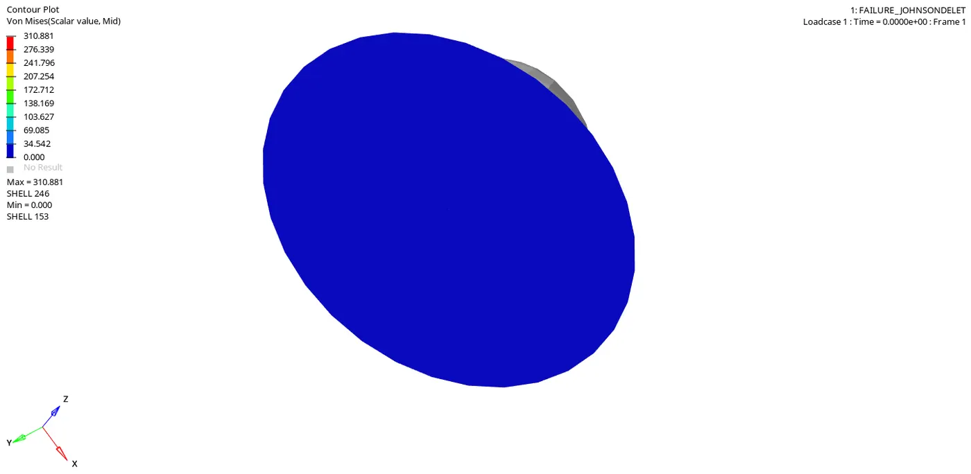
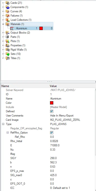
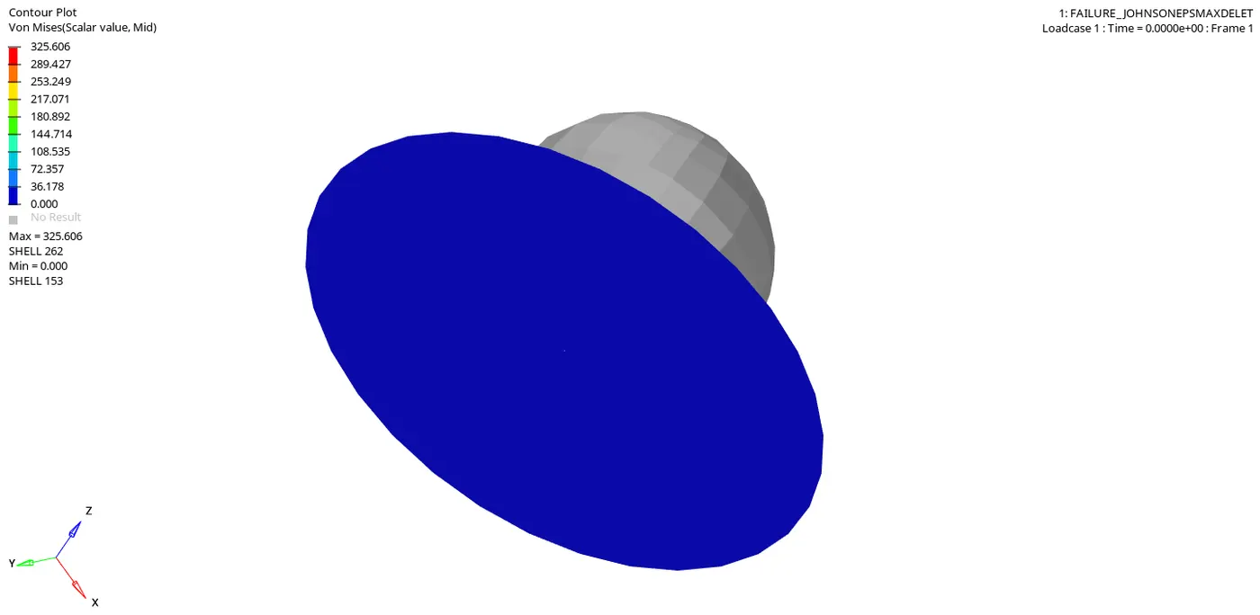
- From the above file just eps max value as zero in material card
- ENERGY ERROR AND MASS ERROR
CYCLE TIME TIME-STEP ELEMENT ERROR I-ENERGY K-ENERGY T K-ENERGY R EXT-WORK MAS.ERR
49296 5.009 0.1010E-03 SHELL 159 1.1% 0.3878E+05 3.947 3.030 0.3837E+05 0.000
49297 5.009 0.1010E-03 SHELL 159 1.1% 0.3878E+05 3.931 3.026 0.3837E+05 0.000
49298 5.009 0.1010E-03 SHELL 159 1.1% 0.3879E+05 3.928 3.022 0.3838E+05 0.000
49299 5.010 0.1010E-03 SHELL 159 1.1% 0.3879E+05 3.935 3.019 0.3838E+05 0.000
49300 5.010 0.1010E-03 SHELL 159 1.1% 0.3879E+05 3.942 3.017 0.3838E+05 0.000
49301 5.010 0.1010E-03 SHELL 159 1.1% 0.3879E+05 3.941 3.017 0.3838E+05 0.000
49302 5.010 0.1010E-03 SHELL 159 1.1% 0.3879E+05 3.936 3.018 0.3838E+05 0.000
49303 5.010 0.1010E-03 SHELL 159 1.1% 0.3879E+05 3.931 3.018 0.3838E+05 0.000
TOTAL NUMBER OF CYCLES : 49304
STARTER+ENGINE RUNTIME = 55.63s (00:00:55)
MAXIMUM TIME STEP. . . . . . . . . . . . . . . . 0.1000000E+31
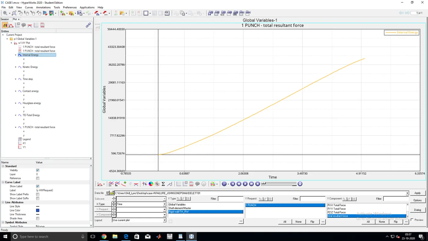
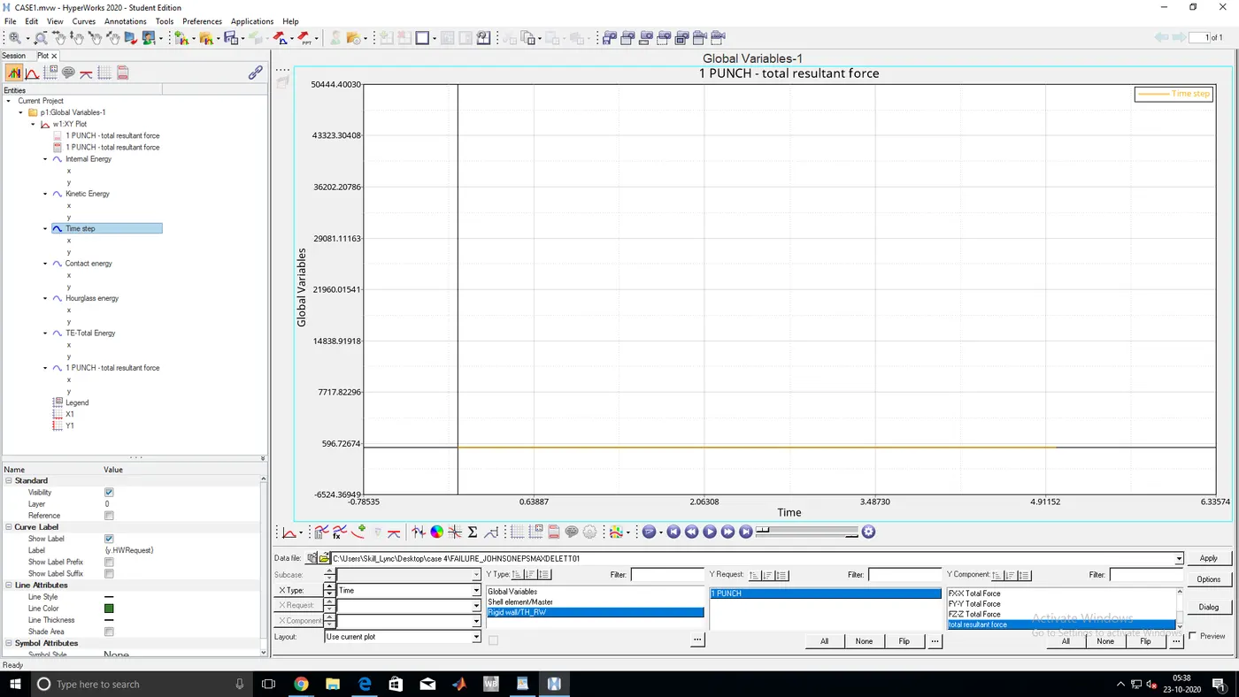
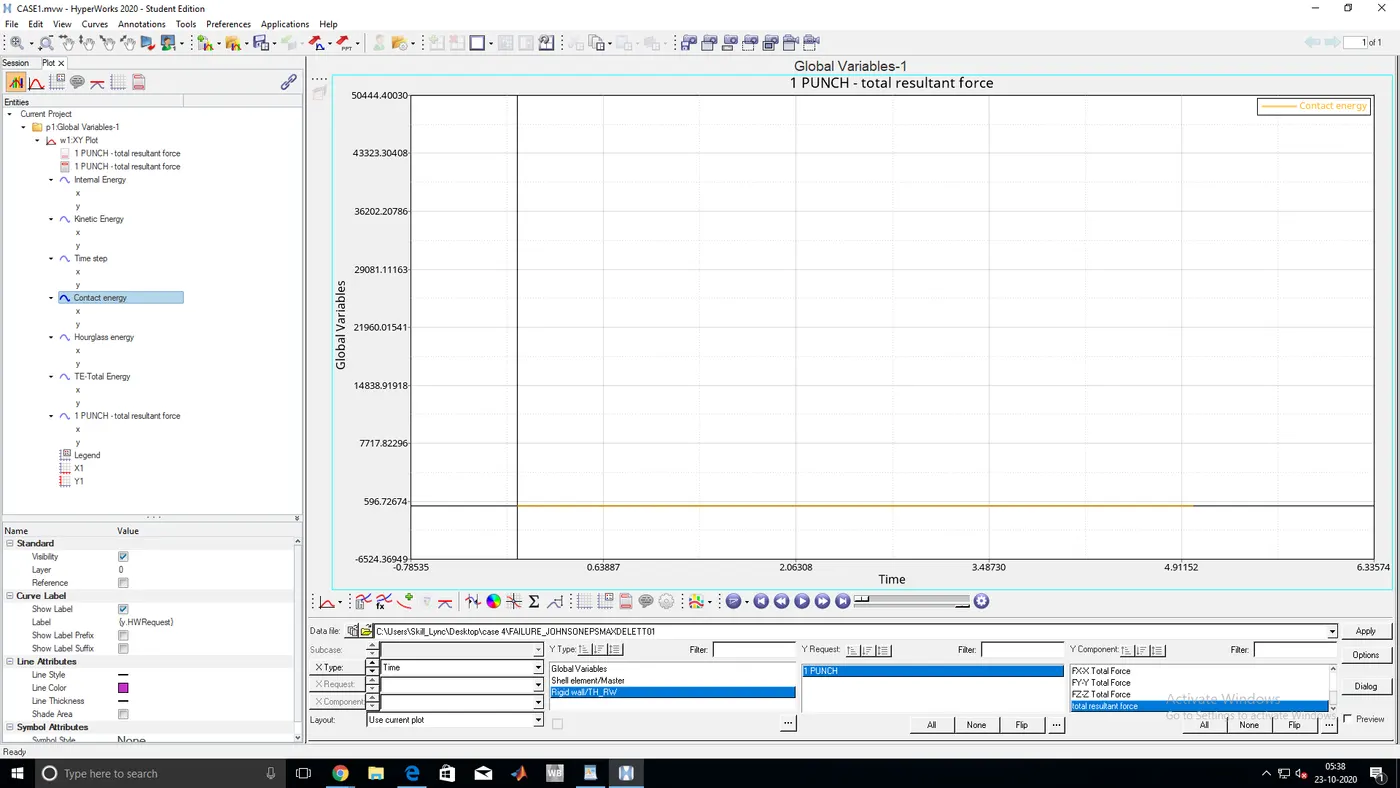
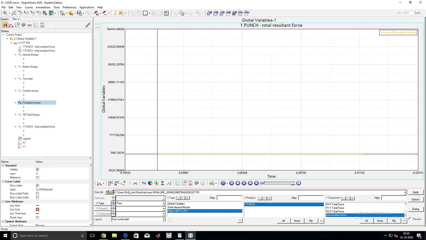
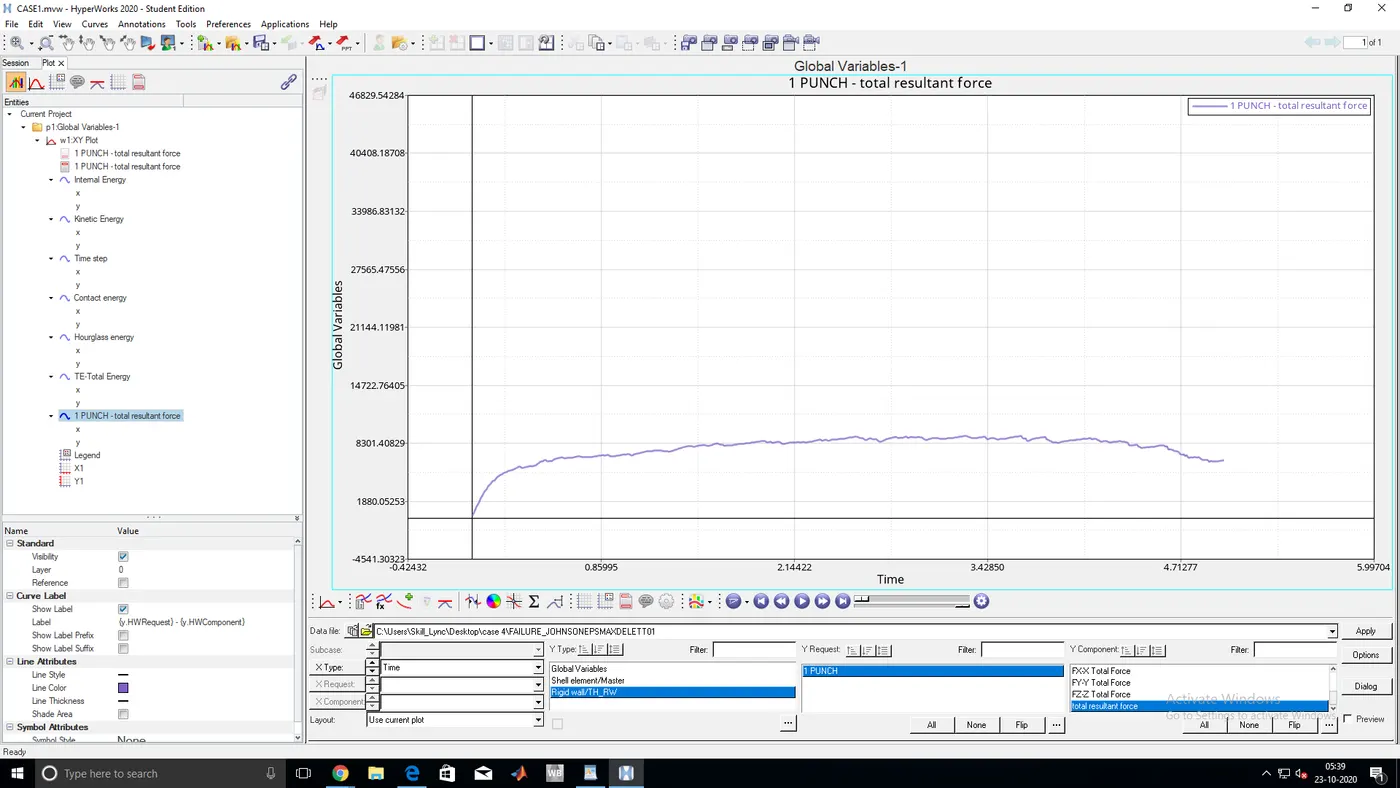
- TOTAL ENERGY,INTERNAL ENERGY,KINETIC ENERGY,TIME STEP,CONTACT ENERGY,HOURGLASS ENERGY GRAPHS
CASE 5:
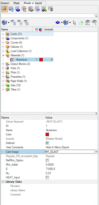
- Convert above model material law as law 1(elastic)
- Give the value of young's modulus, density, and Poisson's ratio.
- And run the analysis
- Run the analysis
- ENERGY ERROR AND MASS ERROR
CYCLE TIME TIME-STEP ELEMENT ERROR I-ENERGY K-ENERGY T K-ENERGY R EXT-WORK MAS.ERR
47960 5.009 0.1096E-03 SHELL 159 1.4% 0.8649E+06 755.3 2630. 0.8564E+06 0.000
47961 5.009 0.1096E-03 SHELL 159 1.4% 0.8633E+06 1681. 3301. 0.8564E+06 0.000
47962 5.009 0.1097E-03 SHELL 159 1.4% 0.8614E+06 3503. 3200. 0.8565E+06 0.000
47963 5.009 0.1099E-03 SHELL 159 1.3% 0.8606E+06 4866. 2402. 0.8565E+06 0.000
47964 5.009 0.1098E-03 SHELL 159 1.3% 0.8614E+06 4742. 1506. 0.8566E+06 0.000
47965 5.010 0.1096E-03 SHELL 159 1.3% 0.8633E+06 3218. 1189. 0.8566E+06 0.000
47966 5.010 0.1095E-03 SHELL 159 1.3% 0.8648E+06 1445. 1694. 0.8567E+06 0.000
47967 5.010 0.1095E-03 SHELL 159 1.3% 0.8648E+06 757.6 2646. 0.8567E+06 0.000
47968 5.010 0.1095E-03 SHELL 159 1.3% 0.8632E+06 1677. 3337. 0.8568E+06 0.000
STARTER+ENGINE RUNTIME = 54.73s (00:00:54)
TOTAL NUMBER OF CYCLES : 47969
MAXIMUM TIME STEP. . . . . . . . . . . . . . . . 0.1000000E+31
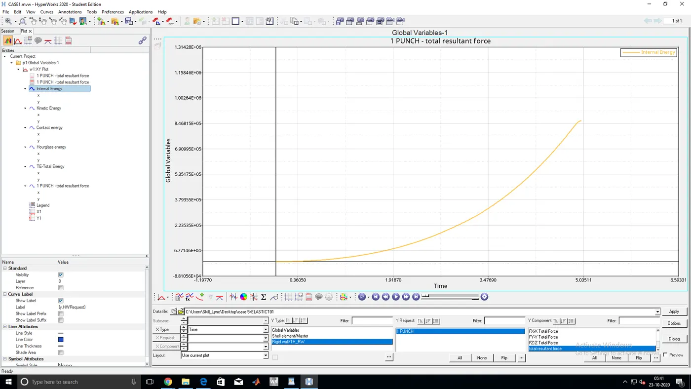
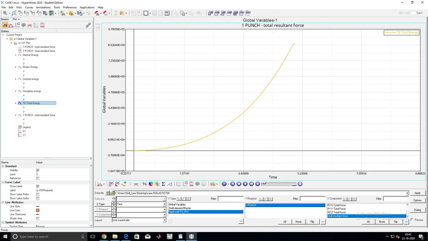
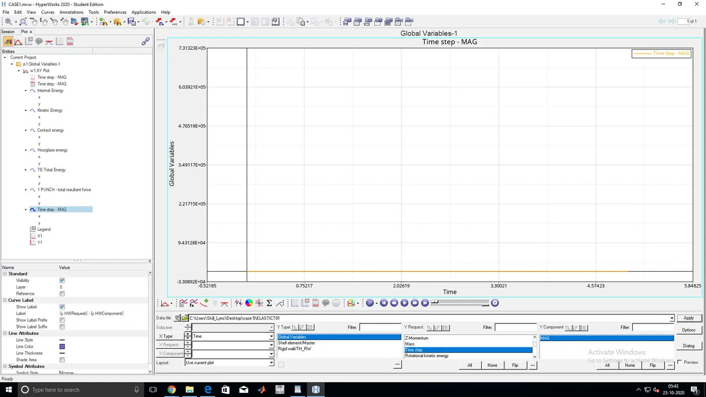
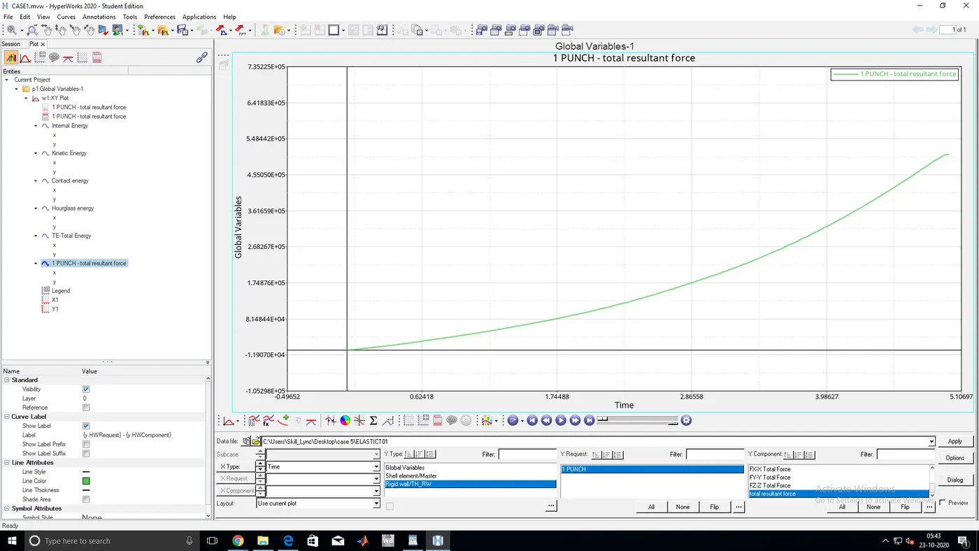
- TOTAL ENERGY,INTERNAL ENERGY,KINETIC ENERGY,TIME STEP,CONTACT ENERGY,HOURGLASS ENERGY GRAPHS
CASE 6:-
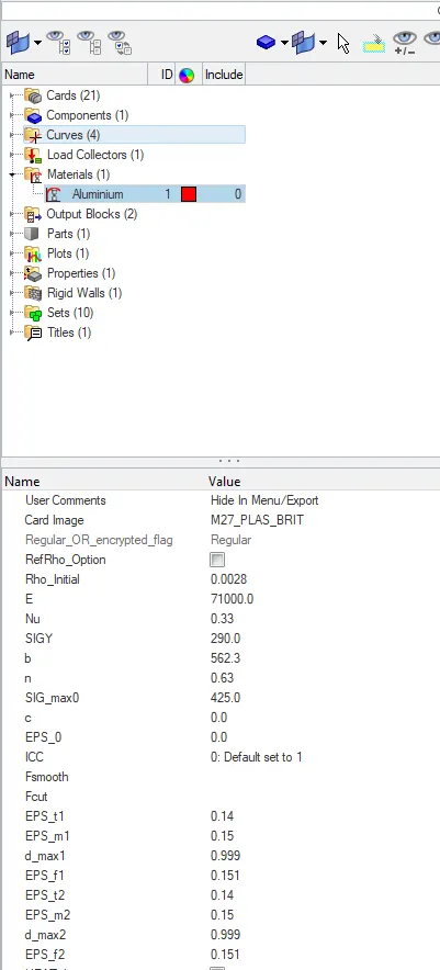
- For this case we need to change the material law as 27 make it as brittle plastic
- Change the properties with respective to the material law
- Run the analysis
- ENERGY ERROR AND MASS ERROR
CYCLE TIME TIME-STEP ELEMENT ERROR I-ENERGY K-ENERGY T K-ENERGY R EXT-WORK MAS.ERR
49500 5.009 0.1004E-03 SHELL 159 0.8% 0.2954E+05 63.90 34.99 0.2940E+05 0.000
49501 5.009 0.1004E-03 SHELL 159 0.8% 0.2954E+05 63.95 35.01 0.2940E+05 0.000
49502 5.010 0.1004E-03 SHELL 159 0.8% 0.2954E+05 64.06 35.04 0.2940E+05 0.000
49503 5.010 0.1004E-03 SHELL 159 0.8% 0.2954E+05 64.21 35.08 0.2940E+05 0.000
49504 5.010 0.1004E-03 SHELL 159 0.8% 0.2954E+05 64.42 35.13 0.2940E+05 0.000
49505 5.010 0.1004E-03 SHELL 159 0.8% 0.2954E+05 64.68 35.19 0.2940E+05 0.000
49506 5.010 0.1004E-03 SHELL 159 0.8% 0.2954E+05 65.00 35.26 0.2940E+05 0.000
TOTAL NUMBER OF CYCLES : 49508
STARTER+ENGINE RUNTIME = 51.39s (00:00:51)
MAXIMUM TIME STEP. . . . . . . . . . . . . . . . 0.1000000E+31
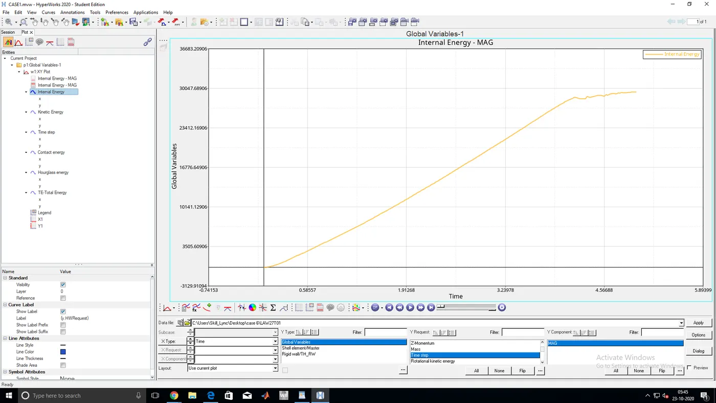
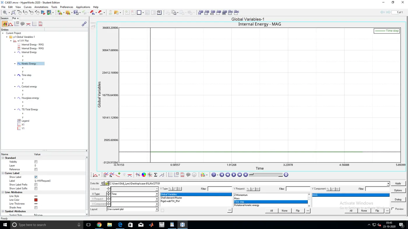
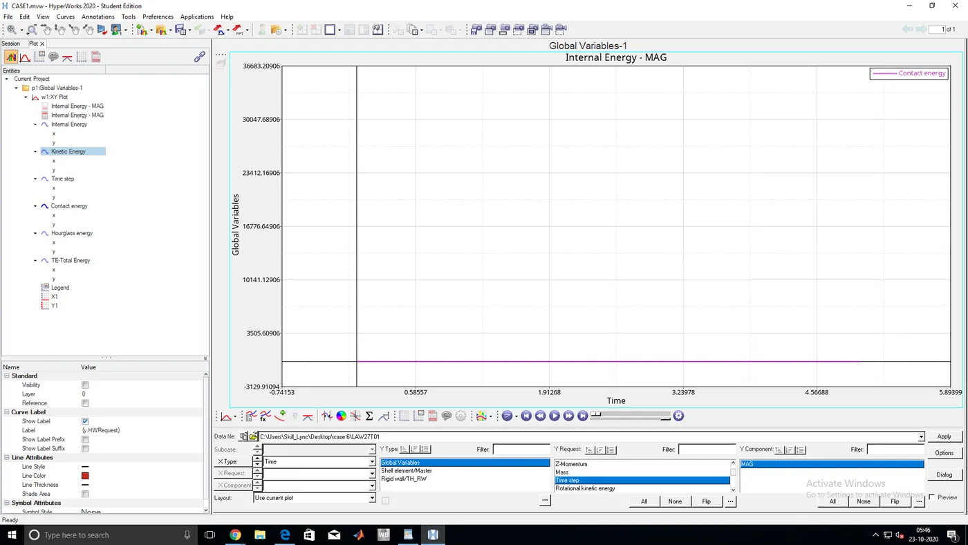
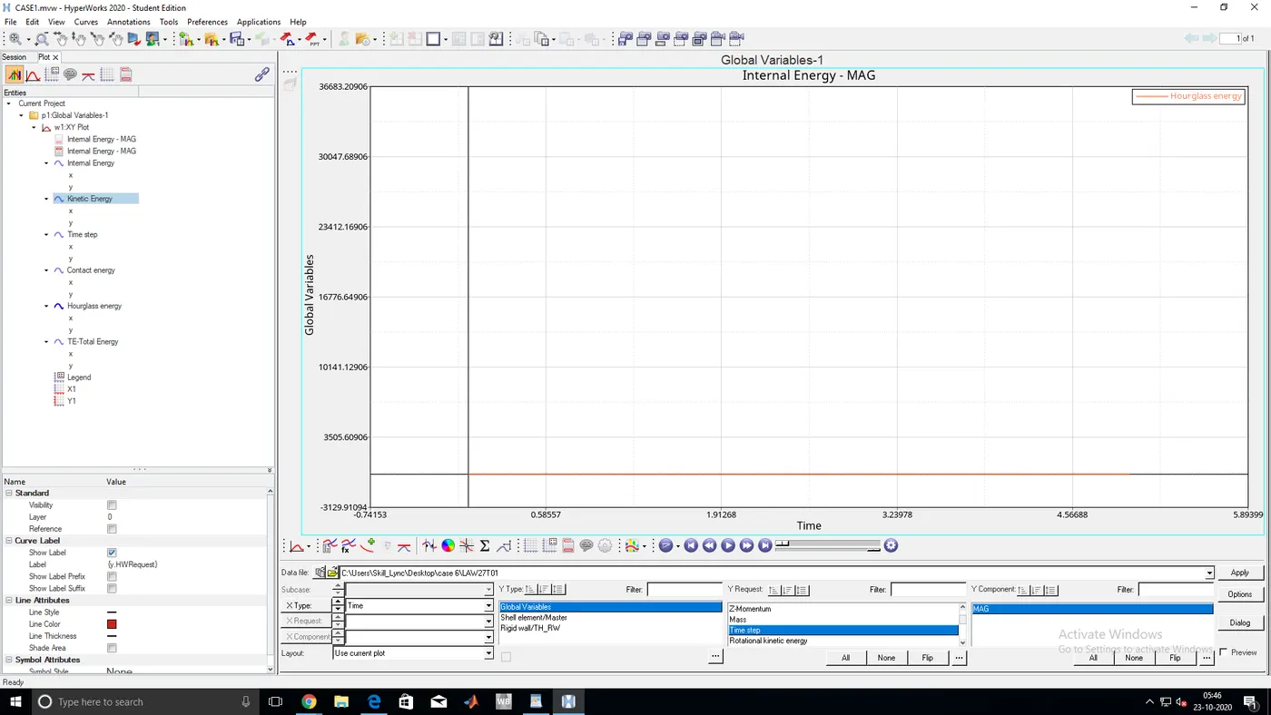
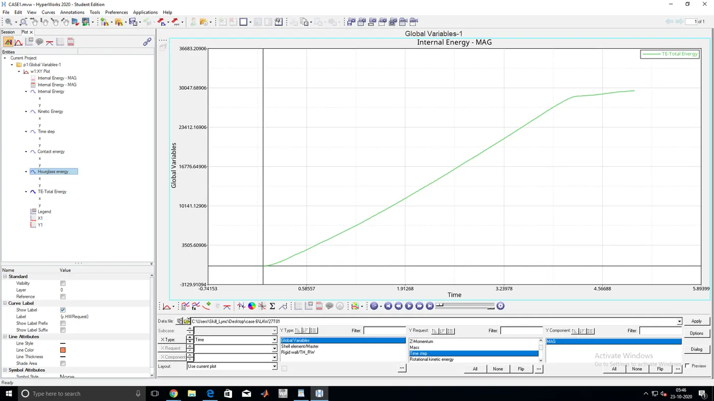
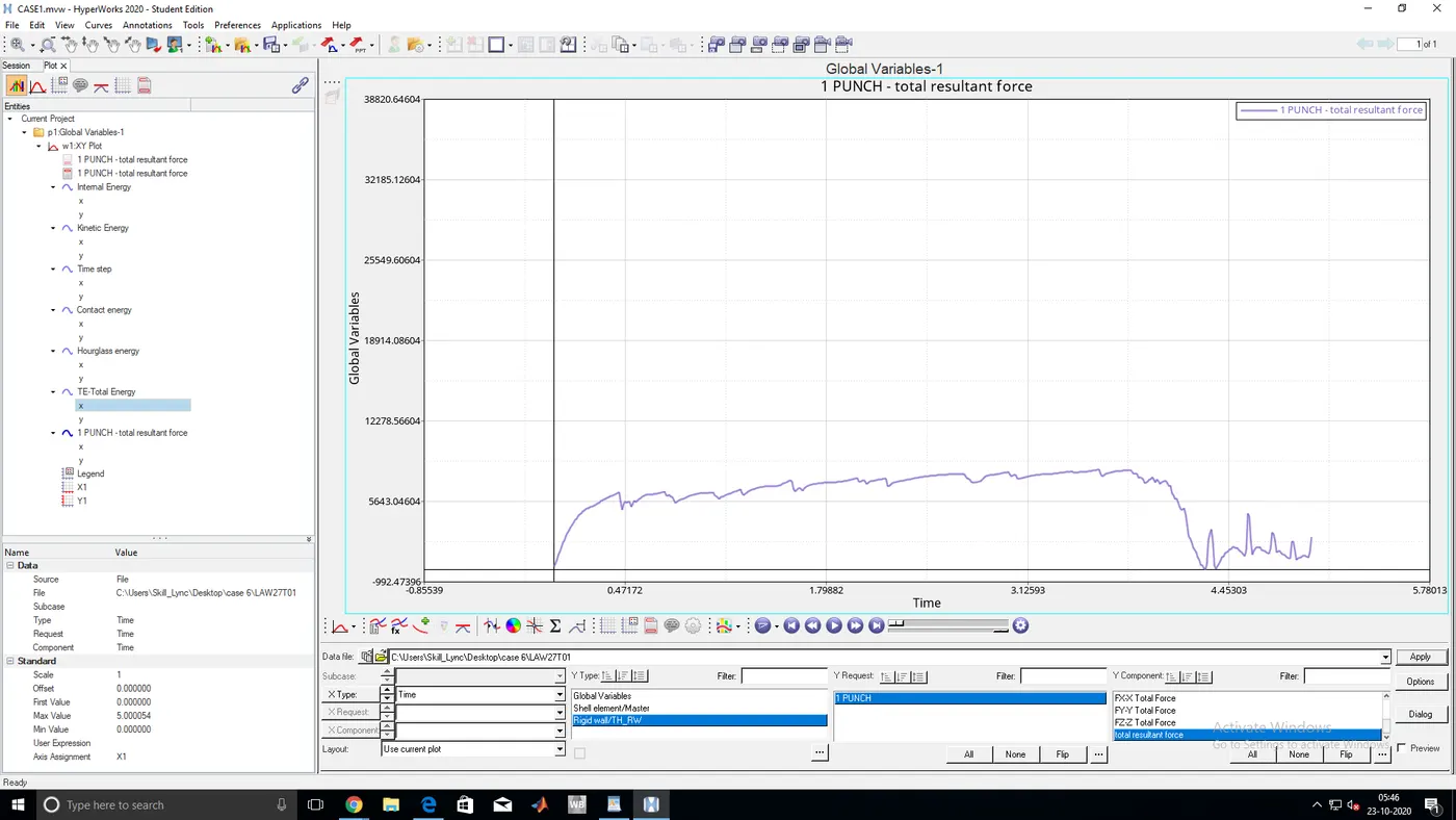
- TOTAL ENERGY,INTERNAL ENERGY,KINETIC ENERGY,TIME STEP,CONTACT ENERGY,HOURGLASS ENERGY GRAPHS
case 7:
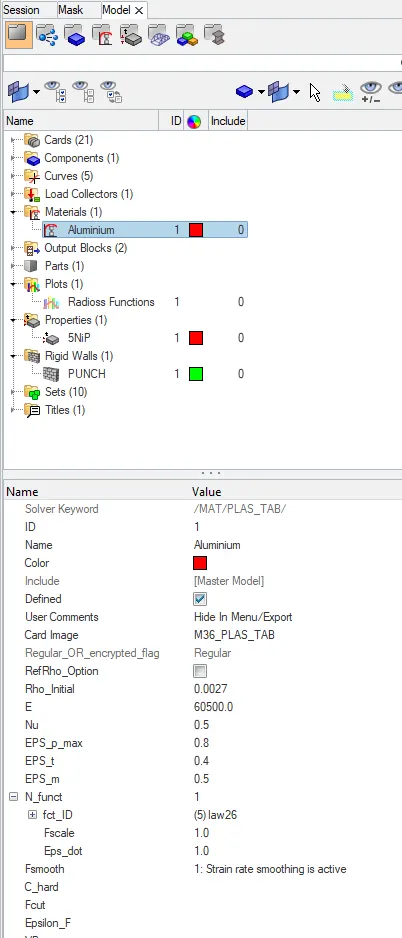
- As we need to change the material to plastic we choose law 36
- Change the values concerning the given data
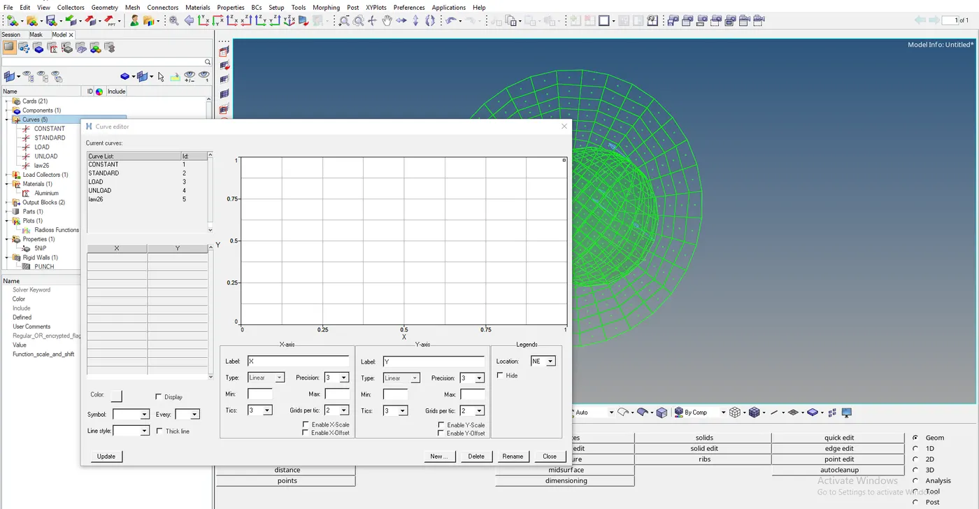
- we need to change the N-function to 1 and need to plot the graph
- so, we need to go to curve select create new and then enter the graph values and create a graph
- Then we need to allocate the material to the curve and run the stimulation

- Run the analysis
- ENERGY ERROR AND MASS ERROR
CYCLE TIME TIME-STEP ELEMENT ERROR I-ENERGY K-ENERGY T K-ENERGY R EXT-WORK MAS.ERR
52074 5.009 0.1017E-03 SHELL 159 4.2% 0.2517E+06 3.500 0.6529E-01 0.2416E+06 0.000
52075 5.009 0.1017E-03 SHELL 159 4.2% 0.2517E+06 3.503 0.6548E-01 0.2416E+06 0.000
52076 5.009 0.1017E-03 SHELL 159 4.2% 0.2517E+06 3.506 0.6567E-01 0.2416E+06 0.000
52077 5.009 0.1017E-03 SHELL 159 4.2% 0.2517E+06 3.509 0.6586E-01 0.2416E+06 0.000
52078 5.009 0.1017E-03 SHELL 159 4.2% 0.2517E+06 3.512 0.6604E-01 0.2416E+06 0.000
52079 5.010 0.1017E-03 SHELL 159 4.2% 0.2517E+06 3.514 0.6622E-01 0.2416E+06 0.000
52080 5.010 0.1017E-03 SHELL 159 4.2% 0.2517E+06 3.517 0.6639E-01 0.2417E+06 0.000
52081 5.010 0.1017E-03 SHELL 159 4.2% 0.2518E+06 3.520 0.6656E-01 0.2417E+06 0.000
52082 5.010 0.1017E-03 SHELL 159 4.2% 0.2518E+06 3.522 0.6672E-01 0.2417E+06 0.000
52083 5.010 0.1017E-03 SHELL 159 4.2% 0.2518E+06 3.525 0.6688E-01 0.2417E+06 0.000
TOTAL NUMBER OF CYCLES: 52084
STARTER+ENGINE RUNTIME = 53.74s (00:00:53)
MAXIMUM TIME STEP. . . . . . . . . . . . . . . . 0.1000000E+31
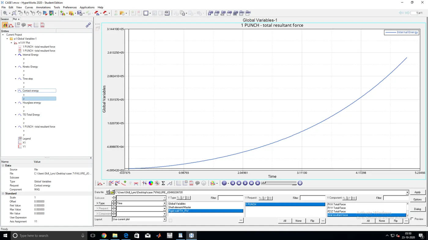
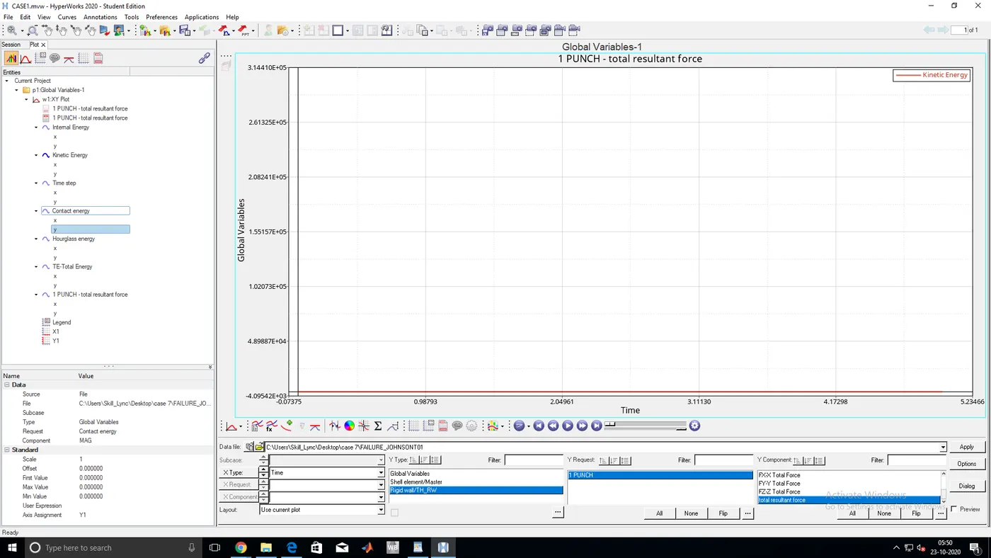
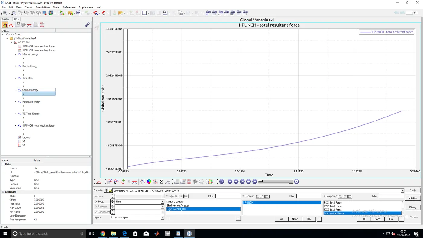
- TOTAL ENERGY,INTERNAL ENERGY,KINETIC ENERGY,TIME STEP,CONTACT ENERGY,HOURGLASS ENERGY GRAPHS
FINAL ANALYSIS OF ALL CASES
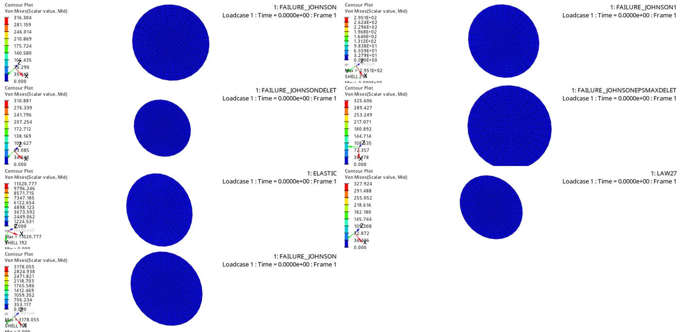
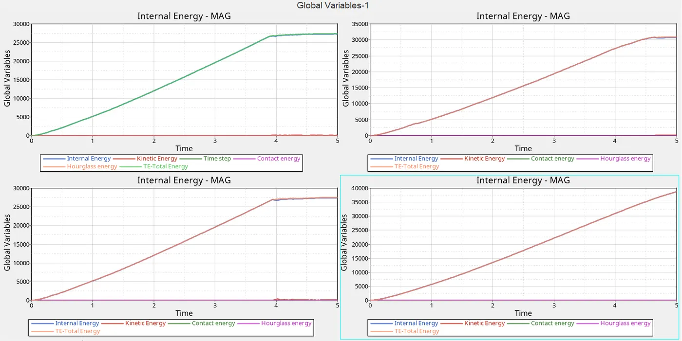
JUSTIFICATION:
- As we can see that the case 1 to case 4 are regarding changing the properties and other cases are change in material law
Case 1:-
- As we run int normally as it has been given, the parameter of the material youngs modulus is given as 710 and given sigma max as 425
- As of now, no element need be failed by the ball is rupturing, because we can see that strain failure rate as set as 15% so that elements that are failing the strain rate the elements are been deleting
- from the graph, we can understand that there is no hourglass so, that hourglass energy is constant and also the contact energy and time step that means the energy is distributed normally
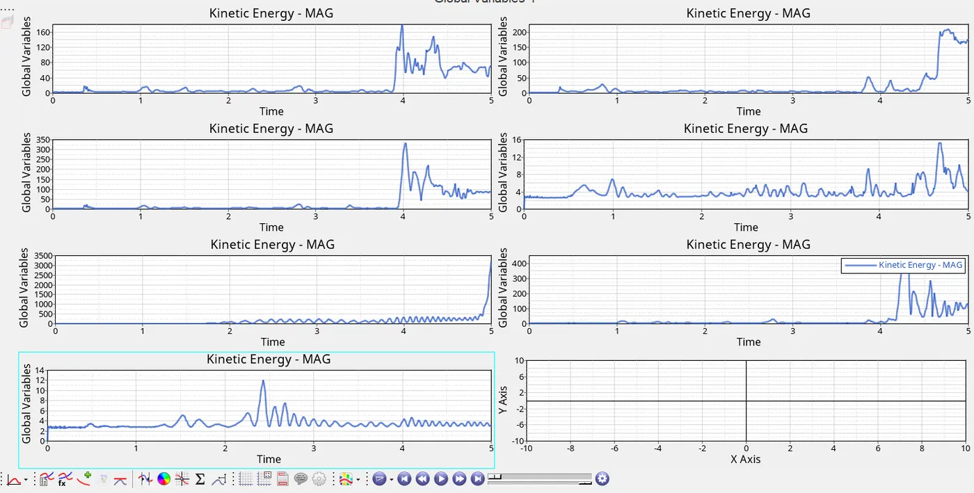
- As we can see that below the kinetic graph after 3.8ms the kinetic energy has been increased due to element failure occurred at that point.
- As we didn't use the Ixfem so that element formulation of the failure element is rupture and the failed element will be deleted
Case 2:-
- It was the same process but we had changed the failure card ifail_sh =1, Davdv =1, Ixfem =1
- I fail _sh is the shear failure flag the major change in this is Ixfem =1
- Ixfem=1 is related to ifail_sh,Dadv=1
- Ixfem =0 the element when it is failed it will be deleted
- If Ixfem =1 the failure element get cracked
- As we the stimulation we can see that crack is been formed that means that the element going to fail we be cracked and then after element will be deleted
- As there we can see that the kinetic energy is being reduced due to ixfem after getting element failure the graph became constant
- But it takes more energy required to reduce the time step and also we can see the constant flow of energy balance
- but the computational time of the solver is high
Case 3:-
- In case 3 we delete the failure card
- so that we cannot control the rate failure of the elements in this if the element crosses the yield point the material will be deleted
- This will cause uneven rupture of the component while undergoing analysis as we that amount all four cases the kinetic energy is high due to uneven rupture
- The computational cycle is 49408 it has taken more cycles to compute
- As the energy error is the same as case 1 but the difference in this is we can not control element failure formulation
Case 4:-
- In this, we kept eps max as 0 so that strain failure rate of elements is kept zero
- So that the element will not fail until or unless it crosses the 10^3 value
- so that we see that the total energy of the graph is increasing
- Until or unless if we didn't specify the value of eps max the element does not undergo element failure
- As in the K.E graph, we can see that the graph is not in a linear manner the energy is been disparate unevenly
Case 5:-
- As in this case, we had to change the law as elastic so that the element doesn't go any rupture or a crack
- In this, the force applied until or unless the analysis cross the young's modulus of the material
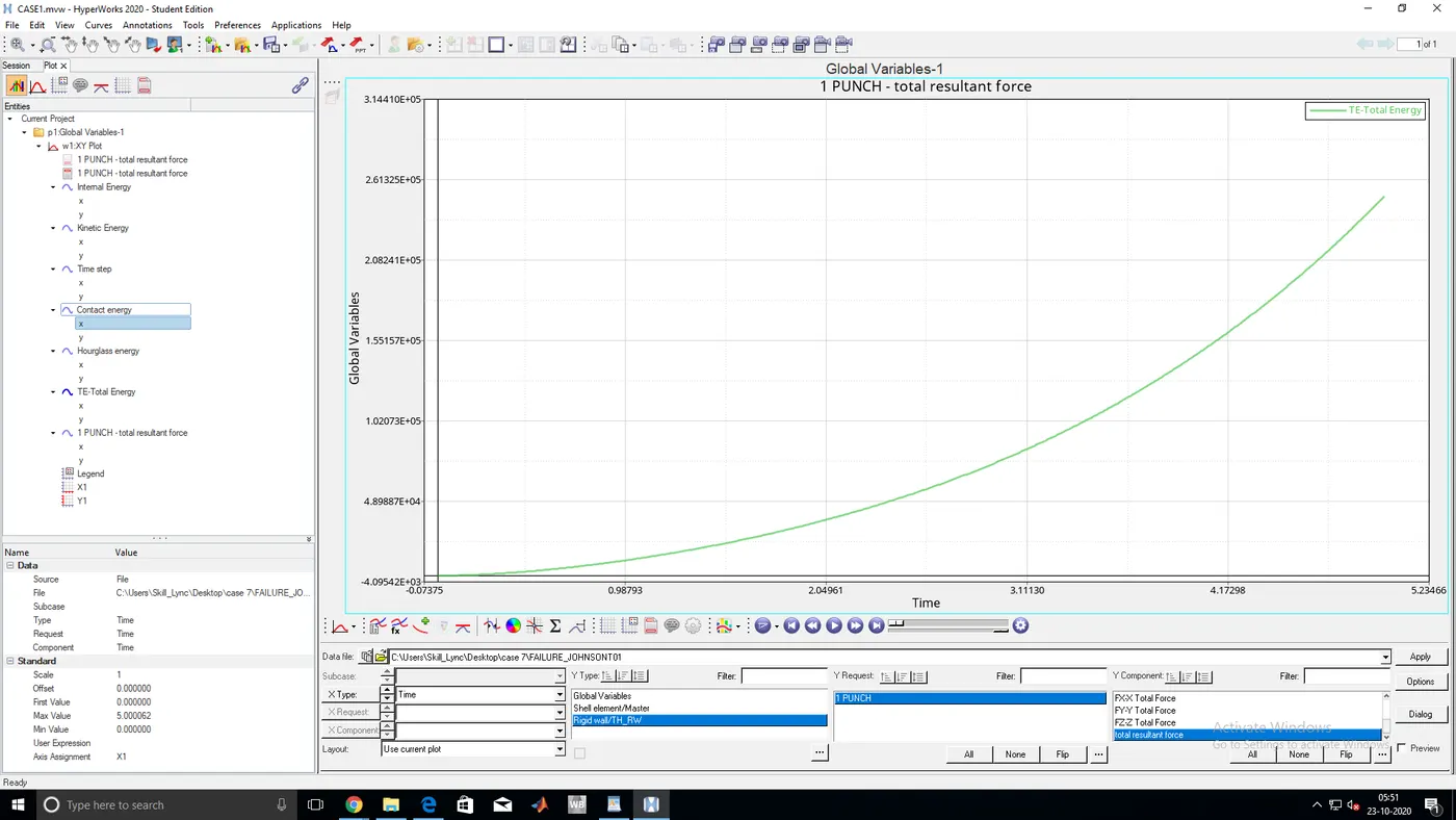
- As we can see that the energy is been increasing with the time
- In the K.E graph, we can see that the energy value cross 3500
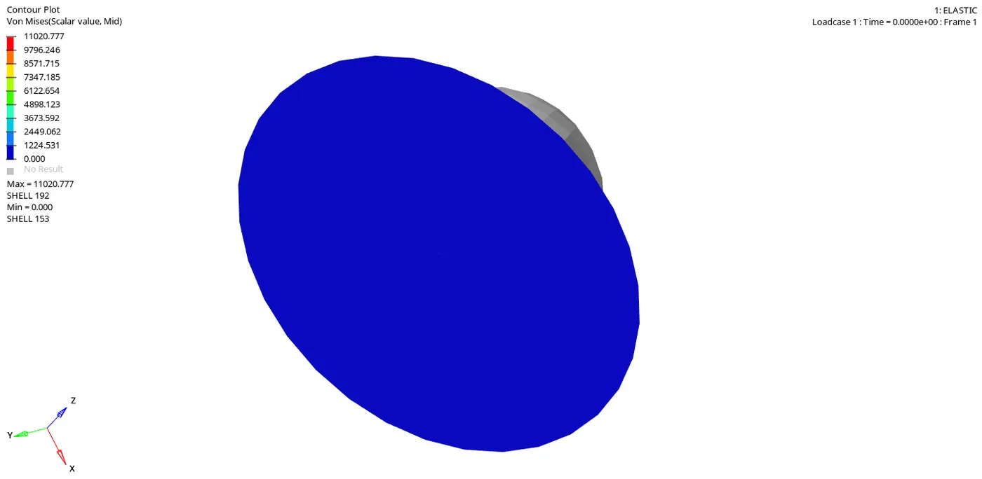
- When the component crosses the yields point after that we get value is garbage
- Here the computational value of von misses stress is been raised to 11200
Case 6:-
- In this case, we had changed the material law of the component as plastic brittle as law 27
- As plastic material can undergo large strain and brittle material will, undergoes large stress
- This is a combination of elastoplastic material
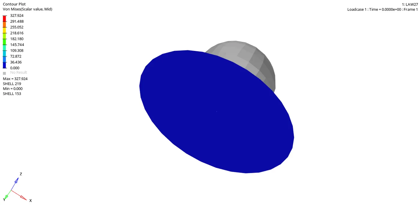
- As we can see that element will collapse at a time at it will be deleted
- In the K.E graph, the K.e constant up to 4.3 after that sudden increase of the energy is been occurred due to failure
- And we can see the desperation of energy is too fast of the crack
Case 7;-
- In the case where we are going to give law as 36, it is a plastic tab
- Here the element undergoes a lot of strain and keeps remains constant
- As we can see that the energy keep on fluctuating
- Because of the plastic behavior, the K.E is been keep on fluctuating due to plastic behavior
CONCLUSION:-
- As we got the idea of the parameters to be considered while doing analysis regarding the material laws
- As of now, law is used for elastic materials
- Law 2 and law 36 is majorly used laws for elastic and plastic materials
- For brittle we going to law 27
- It depends upon the parameter what we have that will help you to choose the law