COMPARISON OF RESULT BY CHANGE IN PROPERTIES OF SHELL
AIM:-Comparison of results with base simulation and improved shell element properties
PROCEDURE:-
- We need to import the model
- And assign different values like frequency and properties to the component before undergoing analysis.
- Then we need to perform the analysis and we need to compare the results.
- Then we need to plot the graph.
- And we need to compare the result.
IMPORTING GEOMETRY
- To upload we need to import the model into hypermesh with respective to the solver
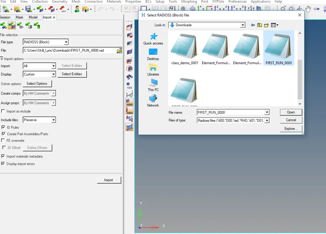
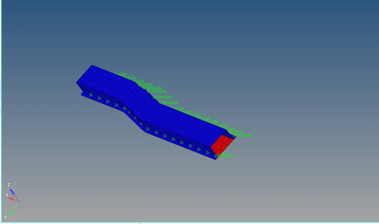
- Importing a file is completed
1.Using the crash beam file from the previous assignment, change the run time to 55 ms.
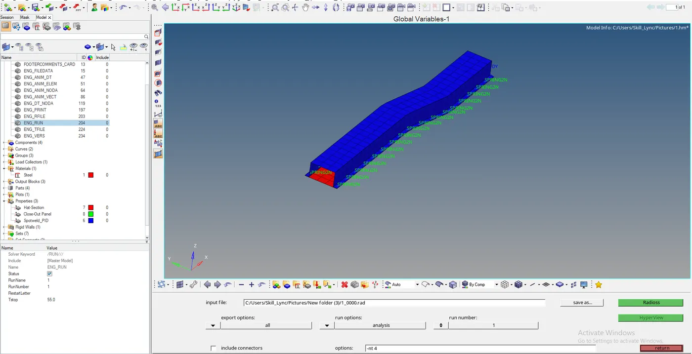
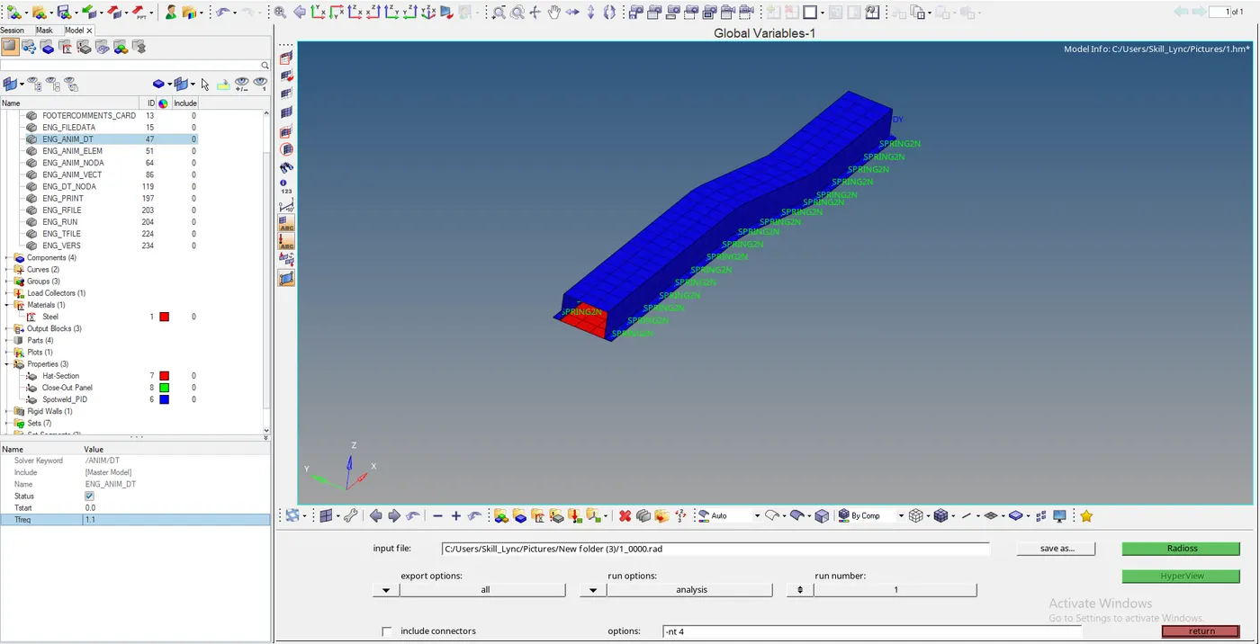
2. Change the number of animation steps during simulation to a minimum of 25 and a maximum of 60.
- As of now, we can take the average number of animation steps and we need to find the frequency and we need to enter it.
Frequency of animation = f = 55/50=1.1
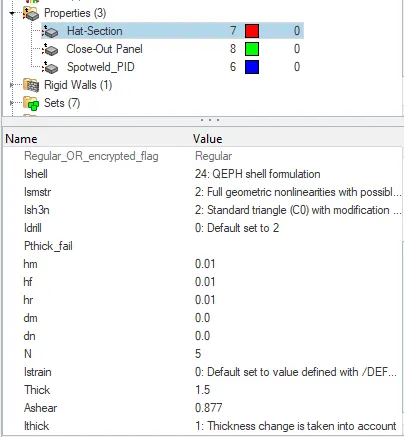
Recommended properties:
| Parameters | Comment | |
|
I shell =24 |
QEPH 4 nodes shells are the best combination of cost and accuracy. | |
|
Ismstr=2 |
Full geometric nonlinearities (default)with possible small strain formulation activation in RADIOSS Engine. | |
|
Ish3n=2 |
Standard 3 noded shell (C0)with modification for large rotation(default) |
|
| N=5 | The number of integration points set to 5 for accuracy bending. | |
|
Ithick=1 |
Thickness change is taken into account for accuracy. |
|
|
Iplas=1 |
Iterative plasticity for good accuracy. |
Ismstr:- To consider the relative shape function of the element and perform calculations
Ithick:- Consider the thickness of the into account while stimulation
- We need to give the properties to the model for 2d elements in this case hat section and the closeout panel must be changed for one of the models.
3. Run the base simulation without any modification to element properties.
- The analysis was done with modification properties for further comparison
- The analysis must be done for the ideal model
model without modification of properties
- we need to go to analysis select RADIOSS and give file location and run it
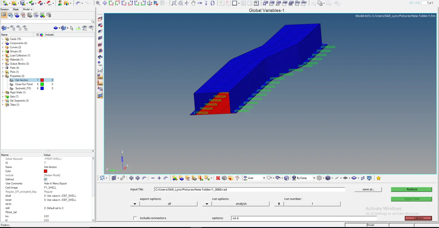
- After selecting the Radioss the get started and the result window will be popped up
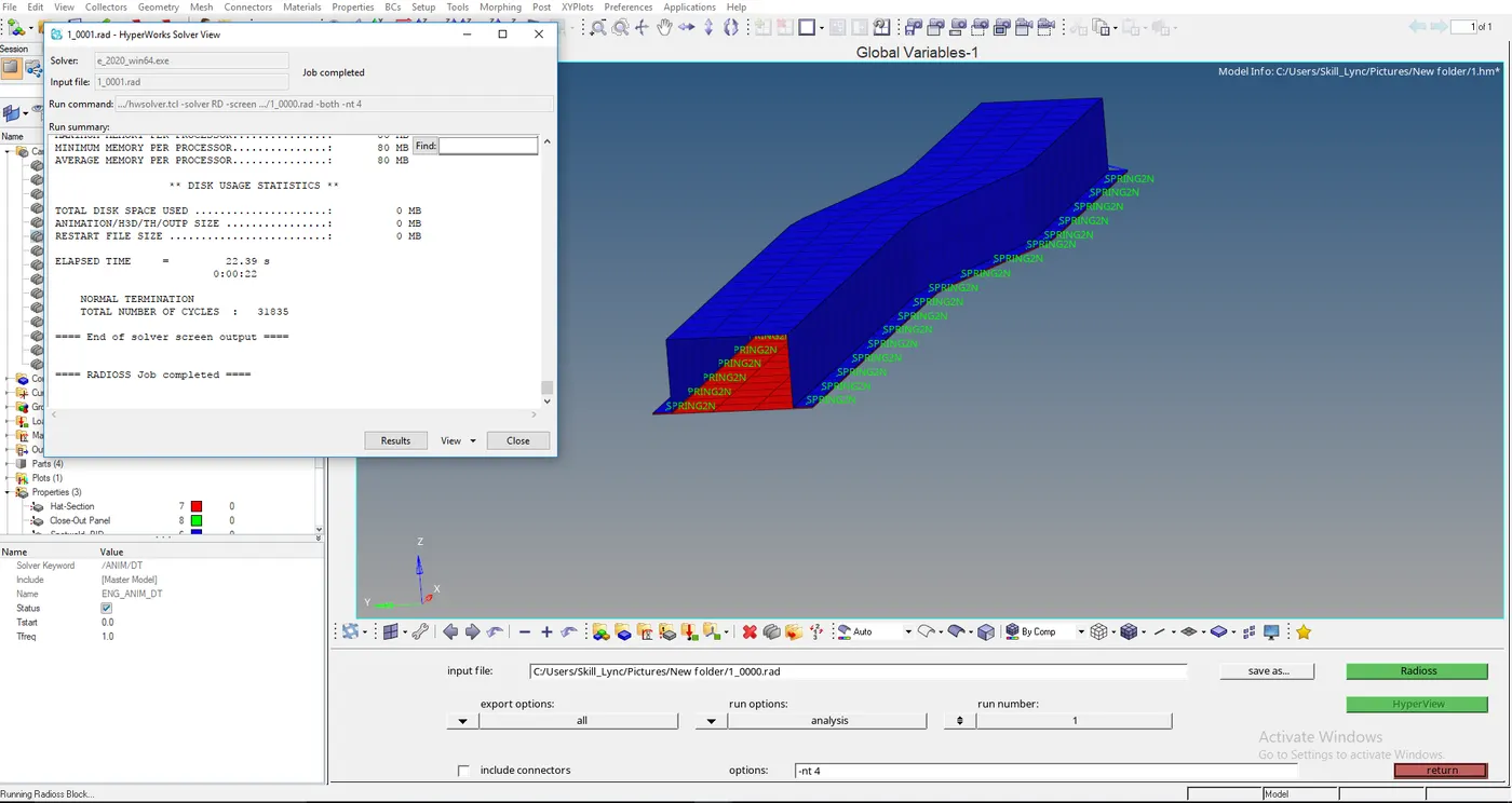
- As same as above after completing a change in properties, the same process must be followed
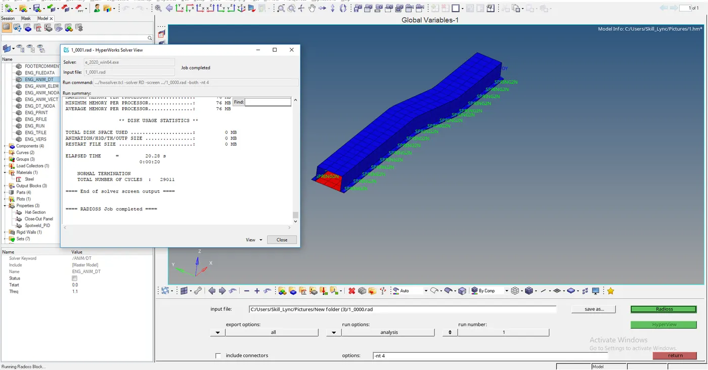
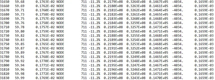
4. At the end of the simulation, do the energy error and mass error checks and determine whether results would be acceptable.
- As to get a good result the error must be negative and decreasing
- As the error must be less than 15%
- If the error started increasing a bit and started decreasing we need to make changes in the model because the problem has occurred in the model
- For the Qeph element, the error percentage accepted as 1-2 %
- Ideally, the error must not exceed -15%
WITHOUT ASSIGNING PROPERTY VALUES

WITH ASSIGNING PROPERTIES TO THE COMPONENT
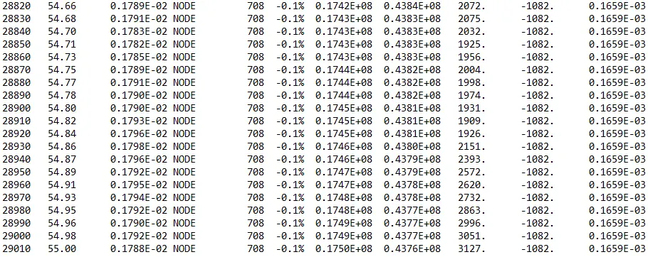
- As both are satisfying the above condition but it is requested to consider zero error the error of the component after changing into QEph is satisfying better.
5. If acceptable, Plot rigid wall forces, internal energy, hourglass energy, contact energy, the total energy of the simulations.
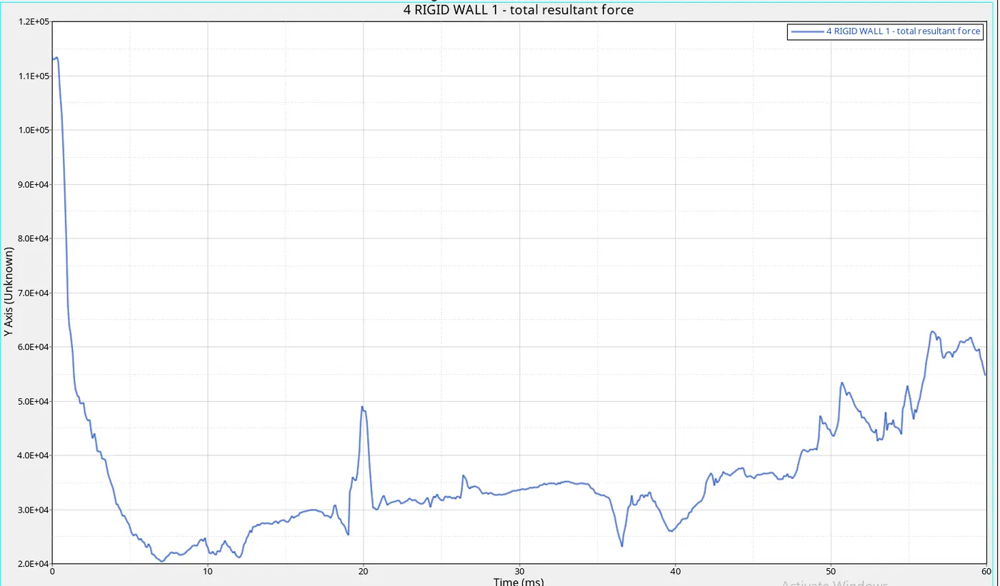
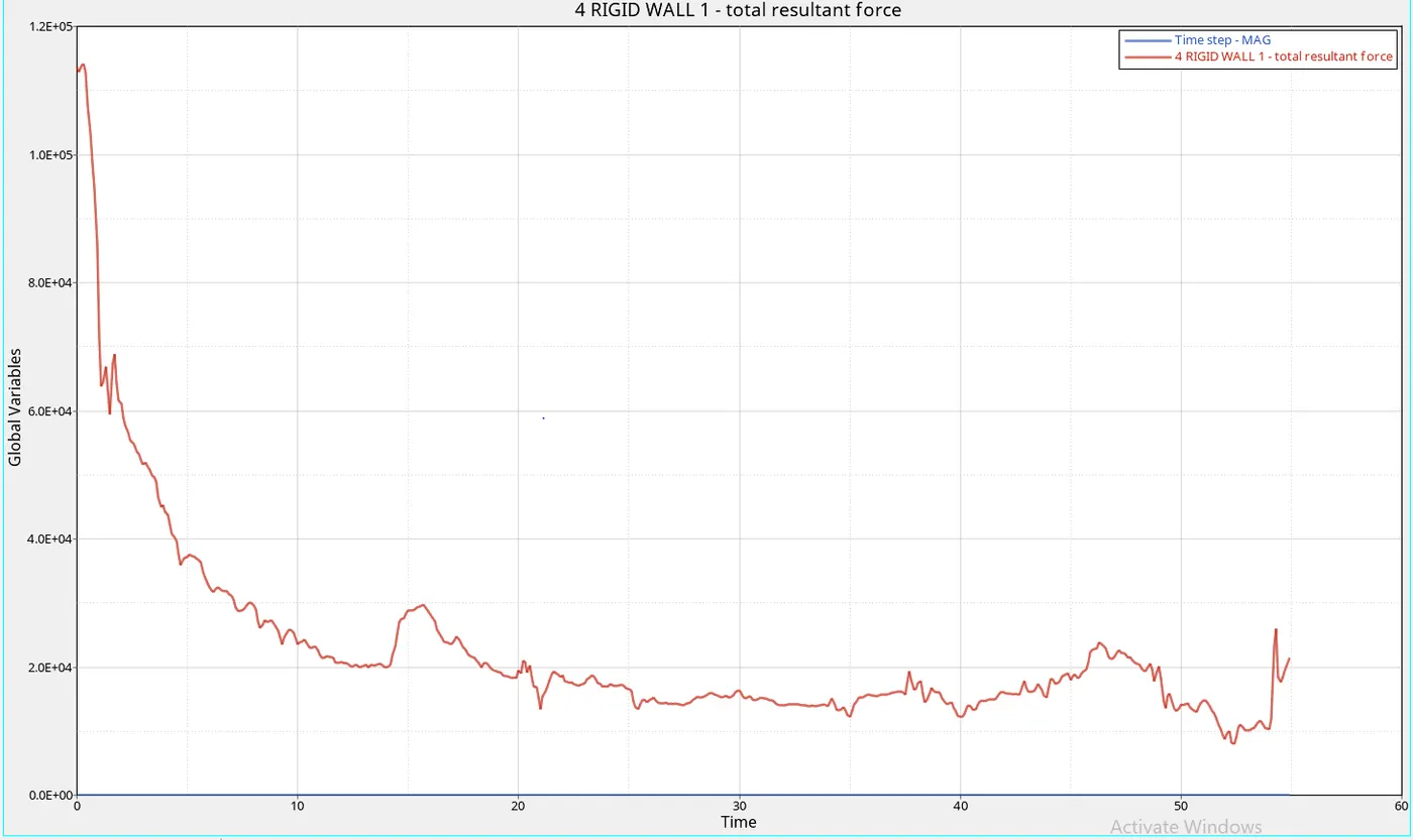
RIGID WALL FORCES
COMPONENT WITHOUT UNCHANGED PROPERTIES
COMPONENT WITH CONSIDERING CHANGE IN PROPERTIES
INTERNAL ENERGY, KINETIC ENERGY, CONTACT ENERGY HOURGLASS ENERGY TOTAL ENERGY
COMPONENT WITH CONSIDERING CHANGE IN PROPERTIES
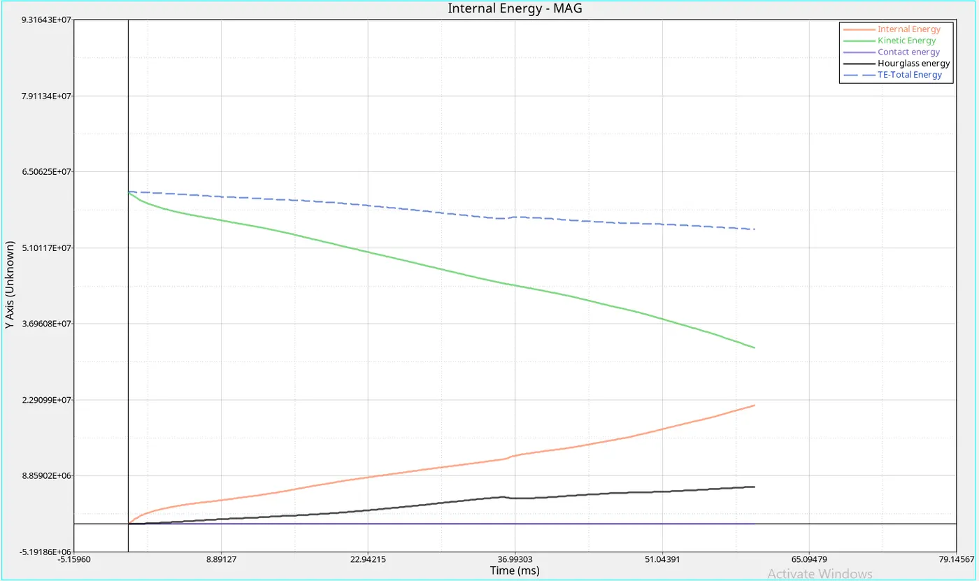
COMPONENT WITHOUT UNCHANGED PROPERTIES
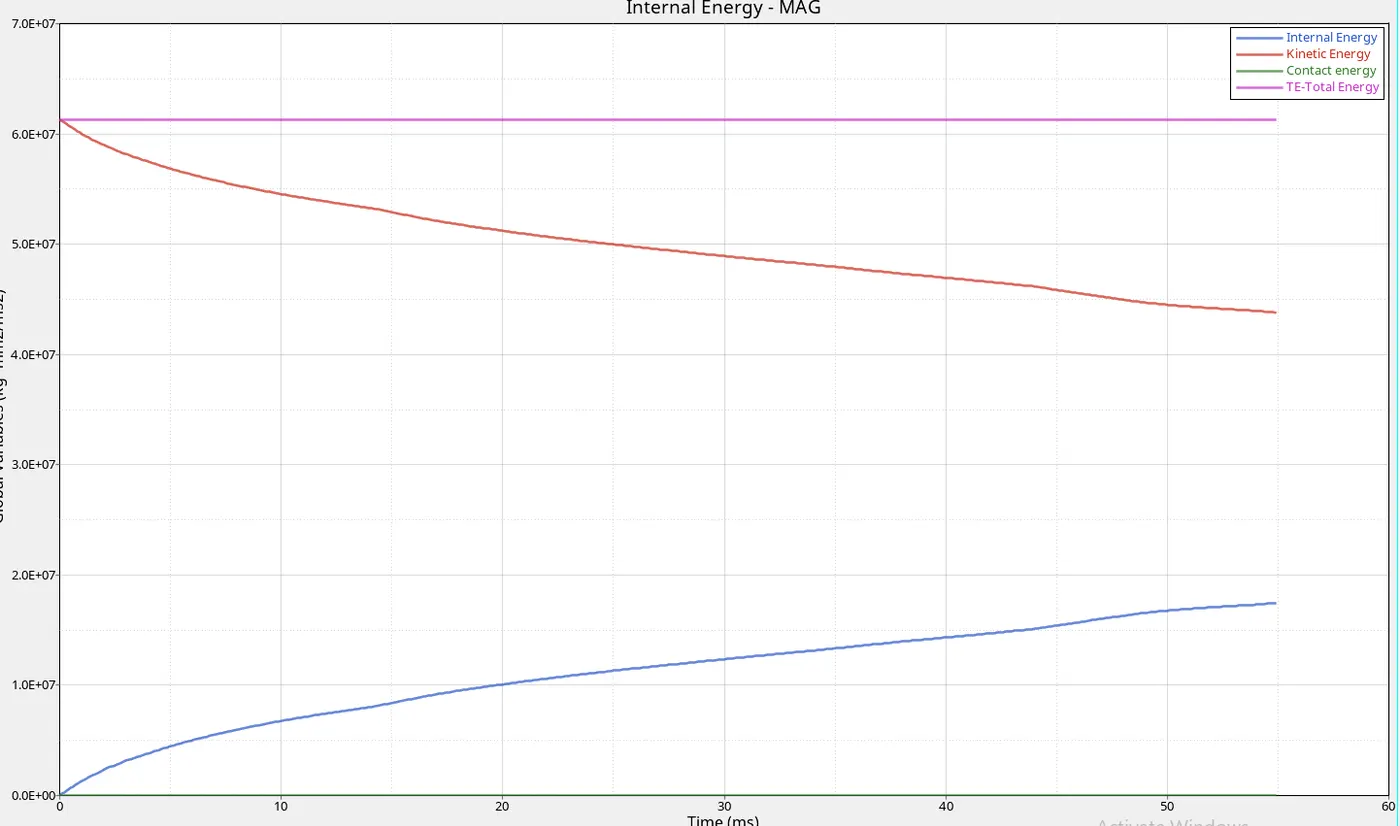
- Due to uneven transition of the element the energy is constant
TIME-STEP
COMPONENT WITHOUT UNCHANGED PROPERTIES
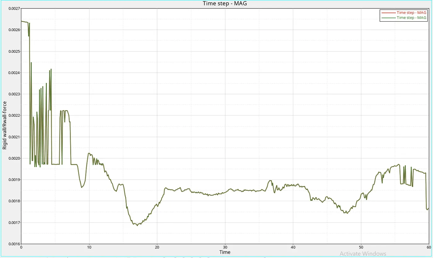
- As we can see the line is going flat it not do because the major concentration is at the center
COMPONENT WITH CONSIDERING CHANGE IN PROPERTIES
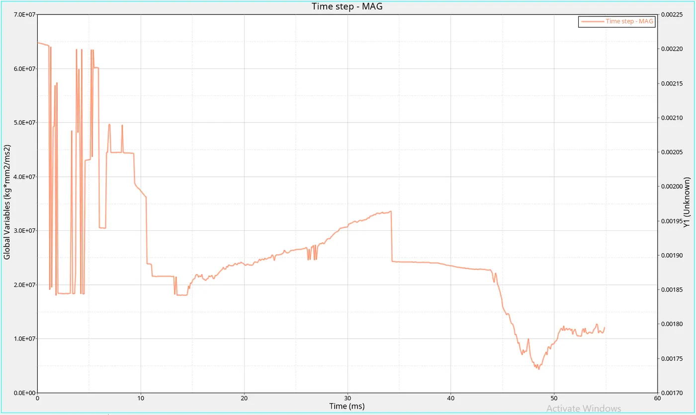
- As the element is kept in Qeph the center portion of the object is captured accurately
VON MISES STRESS
COMPONENT WITHOUT UNCHANGED PROPERTIES
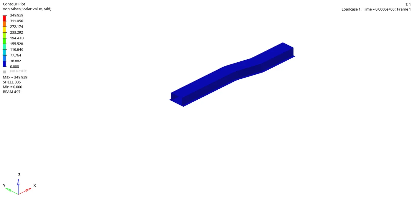
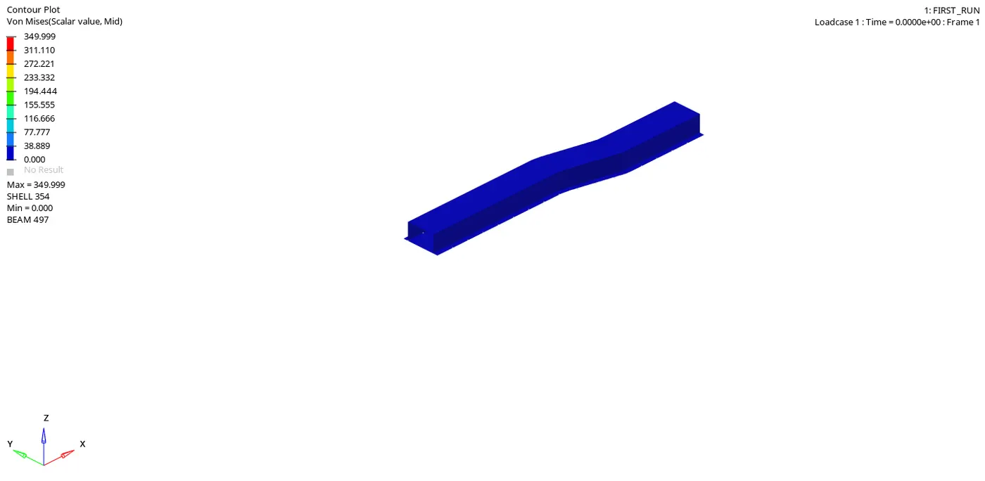
- As we using Qeph the hourglass issues will be reduced and the result will be accurate
- As if we use Q4 the hourglass will be presenting and displacement in it will be zero
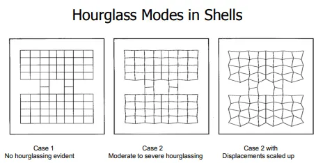
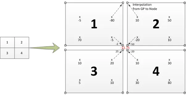
- As for element having one integration point the chances of the hourglass is high
- If there are more no of integrating points are present hourglass will be reduced
- we must keep timestep below critical time if we keep them less than it then element after that time result will not capturing
- There are two types of method to reduce the hourglass one is the vicious method and the integration method
- As from the velocity of sound from another element find that there is hourglass energy from that compiler will know the hourglass area
- To reduce hourglass one method is to increase the stiffness of that other is to apply a resistive force to the elements which reduce hourglass
- N is the integration point that will along with the thickness of every individual element to reduce hourglass,the below fig is about under an integrated and fully integrated placement of integration points
CONCLUSION
- Understood how to perform explicit analysis
- understood how to reduce frames
- Understood what if time reduces in stimulation
- understood how to reduce the error