Assignment 3-2D Element Formulation Challenge
OBJECTIVE:
- Run the crash test of the given beam with a wall, with existing properties.
- At the end of the simulation, check for the energy error and mass error.
- Plot the rigid wall forces, internal energy, hourglass energy, contact energy and total energy of the simulations.
- Also do the crash test with recommended properties.
- After assigning the properties, check for enrgy error and mass error and plot the energy graphs once again.
- Compare between both the cases.
PROCEDURE:
- Import the rad file using import solver deck.
- From file type, choose RADIOSS (BLOCK).
- From file, choose the file to be opened, click on import.
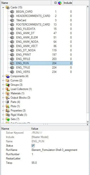
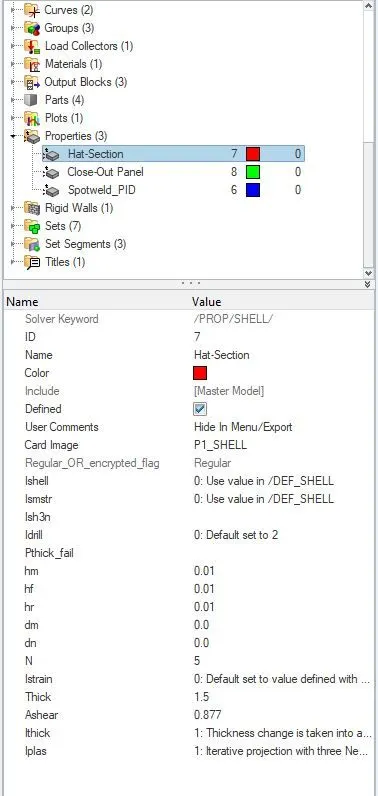
- From model browser, click on card.
- From that, choose ENG_RUN.
- In the entity editor for Tstop, give the final time of run as 55ms.
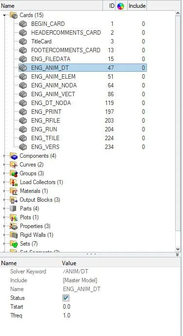
- Now from card, choose ENG_ANIM_DT.
- In the entity editor for Tfreq, give value as 1 for getting 55 animations.
- To run it, go to ANALYSIS>RADIOSS.
- Save the input file.

- Click on RADIOSS.
- Now the solver will do the analysis and show it in hyperworks solid view.
PLOTING GLOBAL VARIABLES AND RIGID BODY FORCES:
- Open Hypergraph 2D.

- In the data file, browse the file which ends with T01, which is a time step file,
- From the box below, select the global variables.
- From the next box, select the variables to plot like internal energy, hourglass energy, contact energy and total energy.
- From the box next to it, click on MAG and then on APPLY.
- Follow the same steps to plot another hypergraph 2D window for Resultant normal force, Resultant tangent force and Total resultant force as shown below.
TO RUN THE SIMULATION:
- To see the results in animation, click on results in solver view.
- Click on apply on the above opened window.
- Click on countour and then on apply.
- Choose the resultant type.
- Click on apply.
- Then click on the play button to see the animation based on the countour.
CHECK FOR ENERGY ERROR AND MASS ERROR:
1. ENERGY ERROR:
- It is a percentage value in Radioss. If the error is negative, it means that some energy has been dissipated. If the error is positive, there is an energy creation. The error must be less than 15% at the end of computaion. If the error increases that means problem has occured and it may grow to 99.9% with computaion faliure.
- Its ok to have less than 15% and better to have less than 5%, the closer to 0% error the better the computation.
- For QEPH shell Formulation the energy error can be slightly positive since there is no hourglass energy, the computaion is much more accurate. An error of 1% or 2% will be acceptable.
CASE 1: WITH ALREADY EXISTING PROPERTY:
- Open the .OUT file using notepad, to check for energy error and mass error.
- If the energy error value is negative and decreasing, also is less than 15%, then it is acceptable.
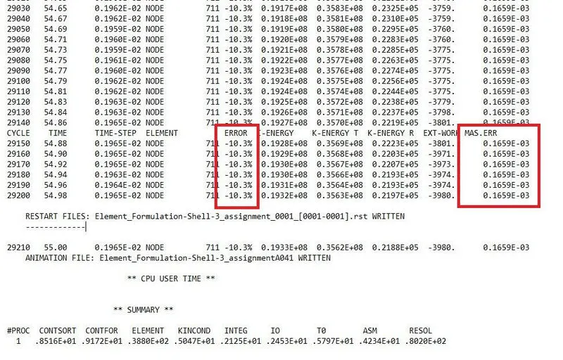
- Here i got -10.3%, so it is acceptable.
- For mass error, it should be less than 5% of the total model mass.
- Our mass error is 0.1659E-03 which is less than 5% of the total mass so its acceptable.
CASE 2:WITH RECOMMENDED POPERTY:
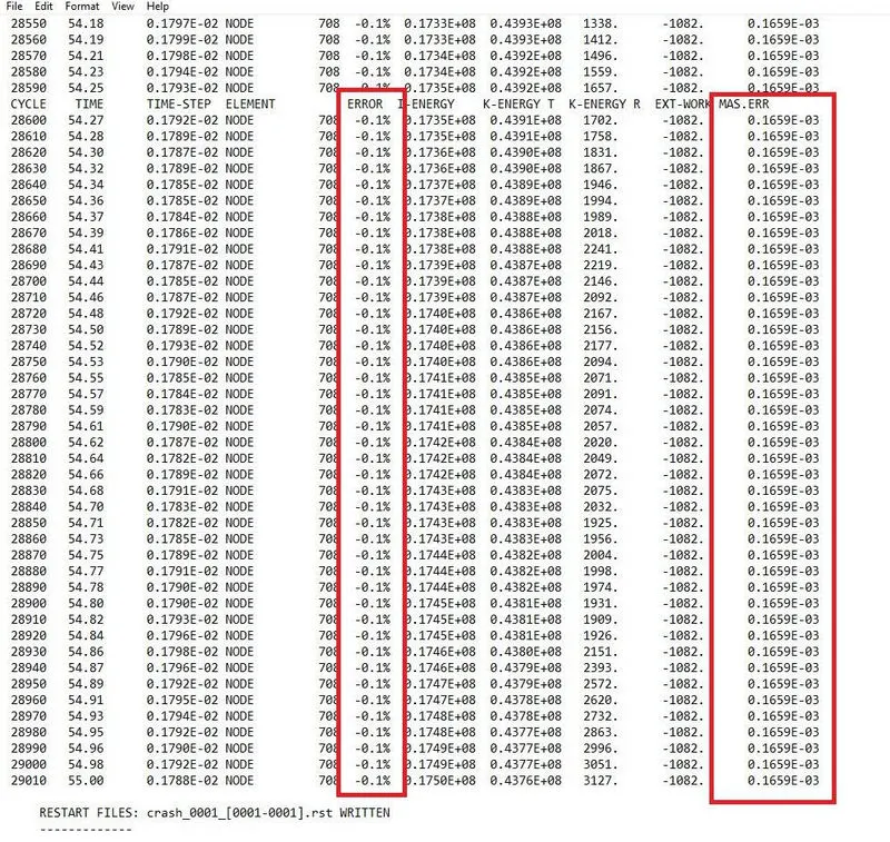
- Here i got -0.1% as my energy error, so its acceptable in case of QEPH
- For Mass error, it should be less than 5% of the total model mass.
- Our mass error is 0.1659E-03 which is less than 5% of the total mass so its acceptable.
ANALYSING THE SIMULATION:
CASE 1: WITH ALREADY EXISTING PROPERTIES:
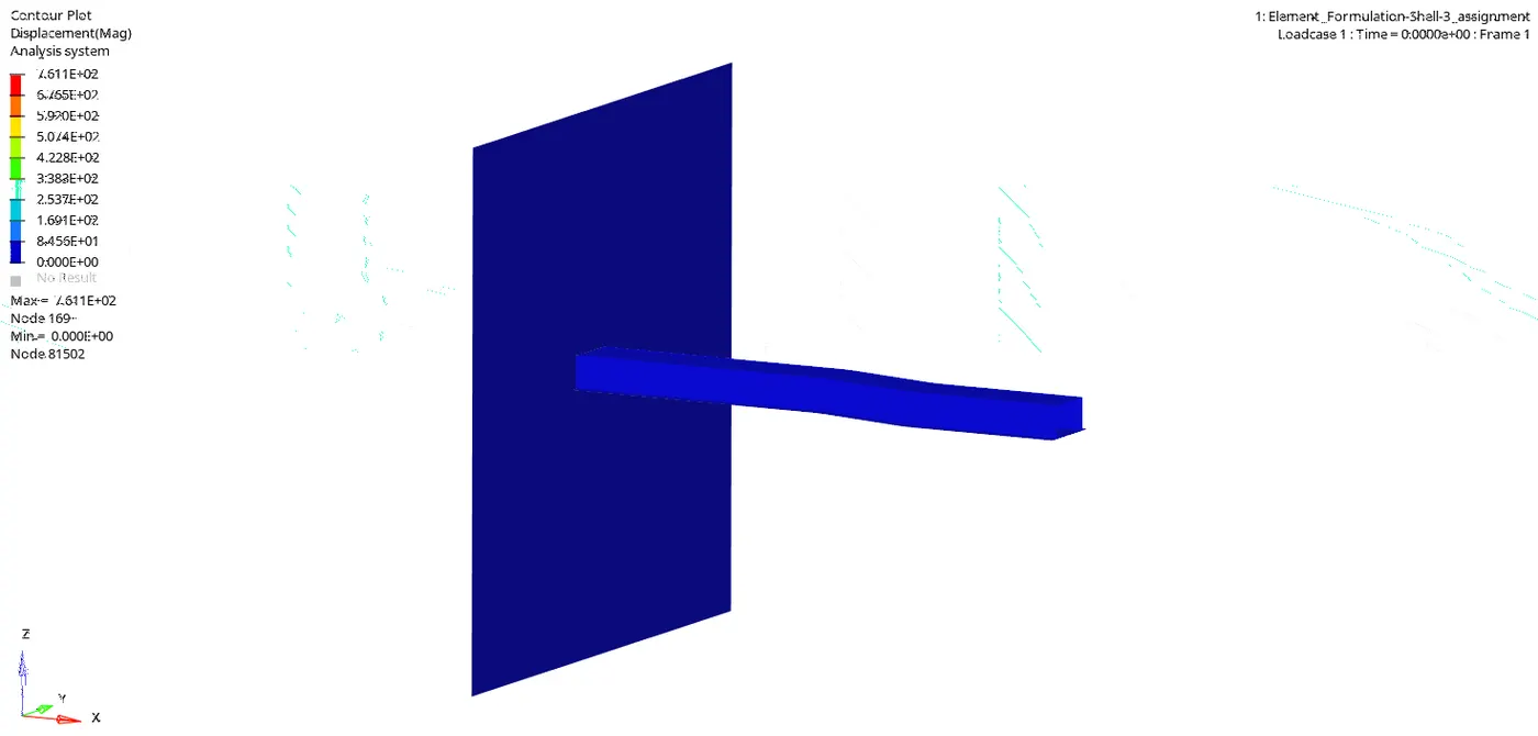
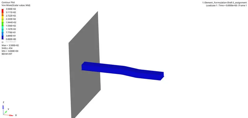
- This is the animation of the simulation without the recommended properties. We can see that the beam is hitting against the wall.
- The animation is based on the displacement. We can find that the nodes on the beam near the wall is not displaced much, and the nodes on the other end of the beam is displaced the maximum.
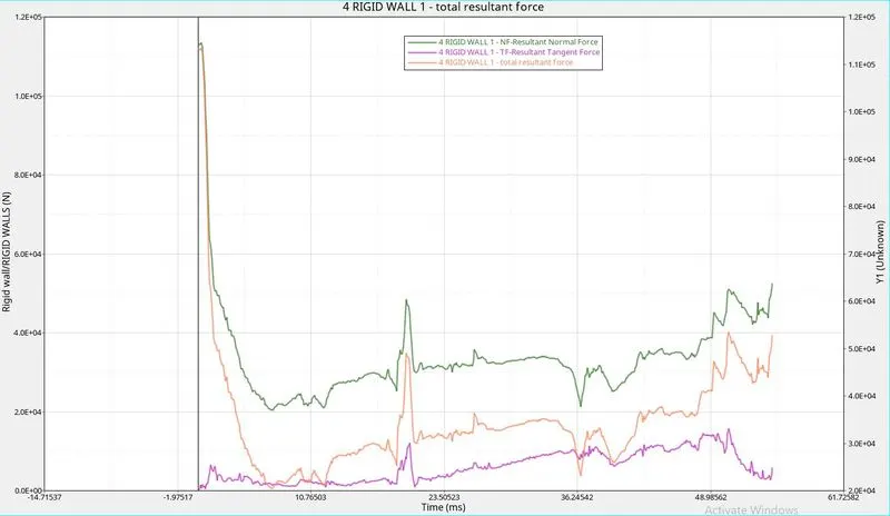
1. RESULTANT NORMAL FORCE: This is the force applied normal to the body. In the initial stage we can see that when the impact happens there is a huge force. After that we can see that the normal force is reducing due to the convertion of the force to frictional force. Also we can see that the force creates deformations on the beam which also reduces the normal force. At a point during the simulation we can see that the beam is tangled too much and more force is applied to bend the beam. That is why we again see a hike in the resultant normal force.After that it again reduces due to the convertion of force to friction and the deformation on beam.
2. RESULTANT TANGENTIAL FORCE: This is the force applied tangential to the body, Which is frictional force. At the beginning there was no tangential force, but as the normal force is applied, there arose a frictional force between the wall and beam. Some normal force is converted to frictional force. At some instance we can see that the normal force is increased and at the same time the frictional force is also increased with it.
3. TOTAL RESULTANT FORCE: This is the sum of resultant normal force and resultant tangential force. That is why the total force is having a pattern which is almost the same as the other.
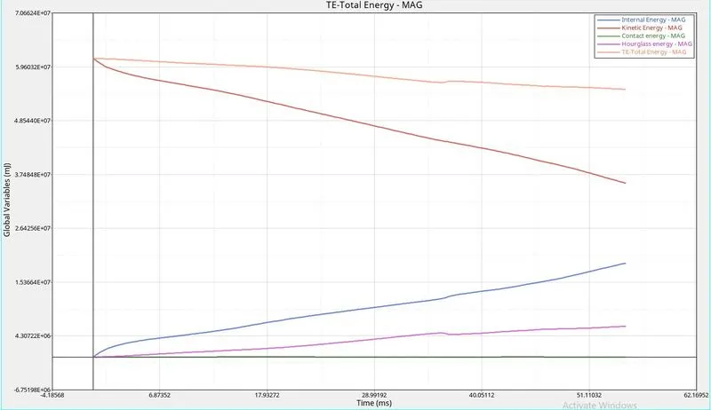
1. INTERNAL ENERGY: Internal energy is the sum of kinetic energy and potential energy. We can see that due to the movement of the body there is frictional force and heat is dissipated.This is the kinetic energy in the body. so it increases by time so the graph is going up.
2. CONTACT ENERGY: It is formed by the contact of the two bodies . Here we can see that there is no formation of energy on the rigid wall while colliding of 2 bodies that is why the contact energy is zero
3. HOURGLASS ENERGY: The force and displacement provides zero stress and strain on the integration points of the elements, Then the stiffness calculation is not done and the body enters hourglass deformation. Thus, over here the body is deformed a bit without any stress and by time this deformation goes on increasing so the graph of hourglass is increasing.
4. TOTAL ENERGY: This is the total sum of all the energies in a body. But due to the presence of the Hourglass which is making the calculation complicated , the total energy is been reduced. As hourglass increaces the total energy is been reduced. The hourglass is inversily propotional to the total energy.
CASE 2: WITH NEWLY RECOMMENDED PROPERTIES:
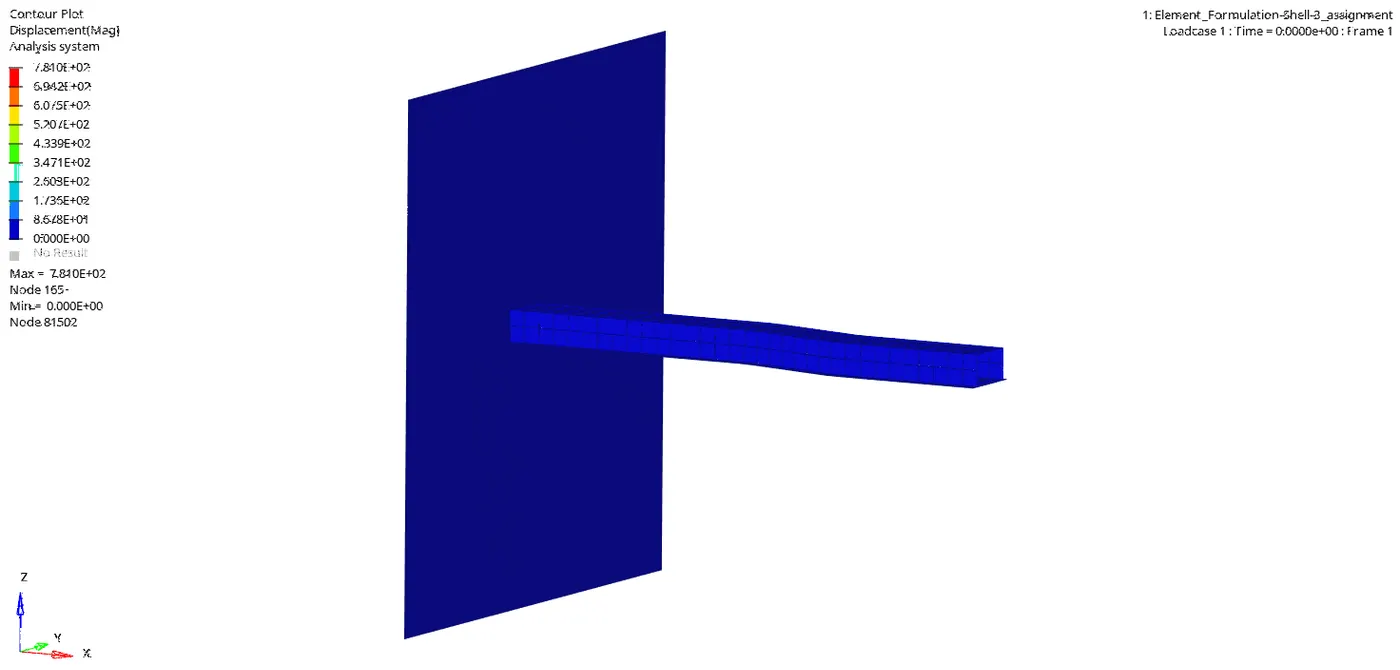
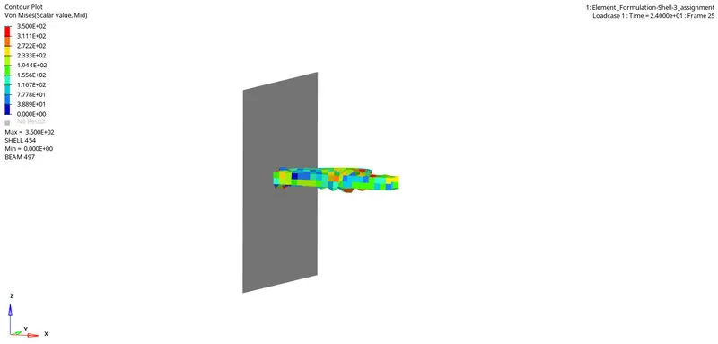
- This is the animation of the simulation after applying the recommended properties. Here we can see that the beam is hitting against the wall.
- We can find that the beam has not only shrinked, but at the same time it is also twisted.
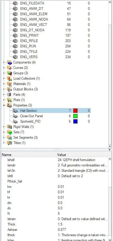
Here we can notice that for the same model, they have got different simulations and different graphs. This is because of the change in property of Ishell to 24, which is QEPH. This is having an improved integration and so the result will be more accurate.
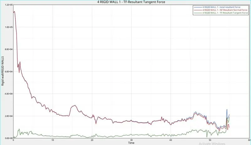
1. Resultant Normal Force :- This is the force applied normal to the body, In the initial stage we can see that when the impact happens there is a huge force. After that we can see that the normal force is reducing due to the convertion of the force to frictional force. Also we can see that the force creates deformations on the beam which also reduces the normal force. Here not as the first condition the beam is not touching each other much while the tangleing of the beam. So no much friction is happening so no extra normal force is needed. The normal force reduces as the process goes on.
2. Resultant Tangential Force:- This is the force applied tangential to the body, Which is frictional force. At the beginning there was no tangential force, but as the normal force is applied, there arose a frictional force between the wall and beam. Here due to the twisting and bending of the beam no much surface is coming in contact with each other of the beam. so only less frictinal force is shown in graph. But at the end frictional force increases as the whole beam is crushed to come closer.
3.Total resultant Force:- This is the sum of resultant normal force and resultant tangential force. That is why the total force is having a pattern which is almost the same as the other.
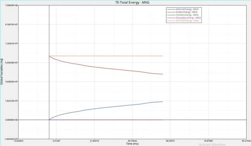
1. Internal energy:- Internal energy is the sum of kinetic energy and potential energy. We can see that as the crashing is going on due to the movement of the body there is frictional force and heat is dissipated.This the kinetic energy in the body. so it increases by time so the graph is going up.
2. Contact energy:- It is formed by the contact of the two bodies . Here we can see that there is no formation of energy on the rigid wall while colliding of 2 bodies that is why the contact energy is zero
3. HourGlass Energy:- In Ishell 24 , perturbation method is used and stiffness is add in the property level. which will reduce the total accumulated hourglass deformation. So here the hourglass energy is reduced due to the use of Ishell 24, Here the stiffness is added in a way that no hourglass energy is produced.
4. Total Energy:- This is the total sum of all the energies in a body. The hourglass is inversily propotional to the total energy .But here the Hourglass is zero because we used QEPH(Ishell24). This shell element formulation is also having hourglass but it is reduced due to the use of improved under integration.