Week 8-Challenge
AIM:
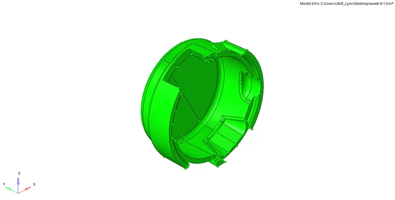
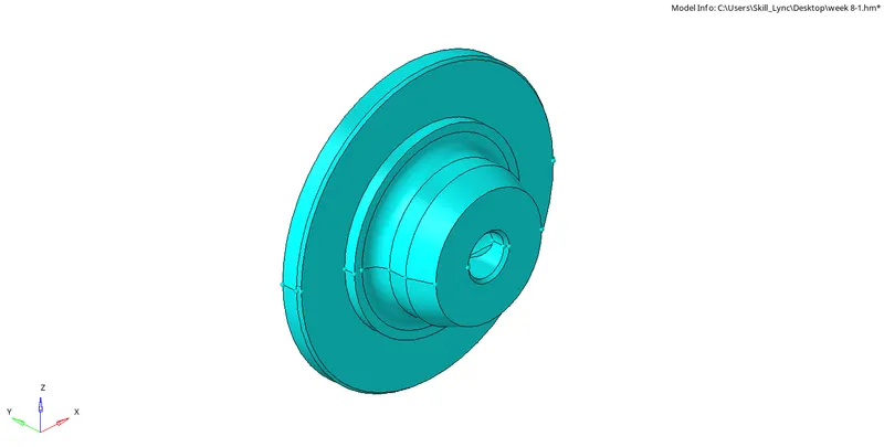
To do 3D meshing of the given components,
with element sizes: Minimum length:2mm, maximum length: 5mm
Target element size: 5mm
Tet collapse: 0.15
CAD MODEL:
PROCEDURE:
step 1: Geometry cleanup
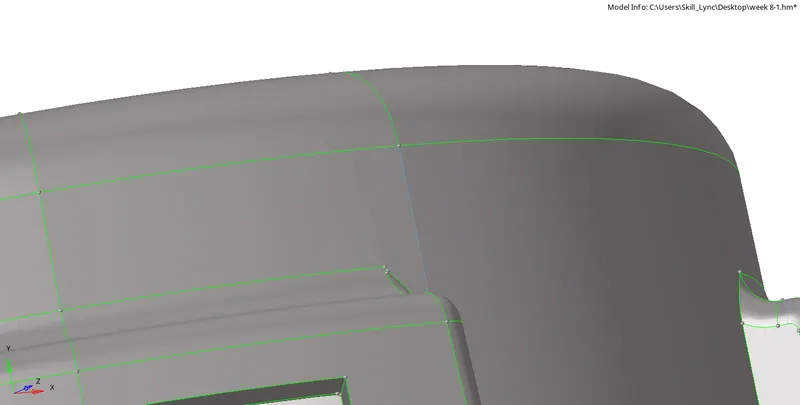
The geometry cleanup is done using quick edit tool from geometry.
The unwanted lines can be toggled using toggle edges option from quick edit tool.
New lines are plotted according to the mesh convenience using split surface node or split surface lines option from quick edit tool in geometry.
step 2: Creating 2D shell elements
- In order to create 2D shell elements, select the surface that needs to be meshed from automesh option in 2D tool.
- Make sure that criteria file has been set.
- Make sure that only tria elements are used for meshing.
- this can be set from preference option on top centre menu of the screen.
- Since only max and min length is given, untick all other options other than max and min length.
- Going surface by surface create the shell elements for the entire surface.
- Some elements may fail for minimum and maximum length. This can be cleared by undergoing remesh and splitting the elements.
- Some quad elements may form due to the splitting of tria elements. These quad eolements can be cleared by remeshing again.
- Thus all the errors can be cleared.
Step 3: converting to 3D tetra mesh
- for converting to 3D elements, make sure that the criteria and parameter files are set according to the provided values.
- For this, go to 3d bar and select tetra mesh parameter.
- given min and max size, (tick for fill void,fill mid nodes,smoothing) and also provide the value for tetcollapse.
- Go to tetra mesh and select the elements and click on mesh.
- Mask the elements and check to make sure that tetra mesh has been conducted succesfully.
- Click on F10 to check for tetcollapse error.
- failed elements for tetcollapse can be cleared by doing remesh and also using translate option by reverse masking the only failed elements with adjacent elements.
- Thus a zero error 3D mesh can be obtained.
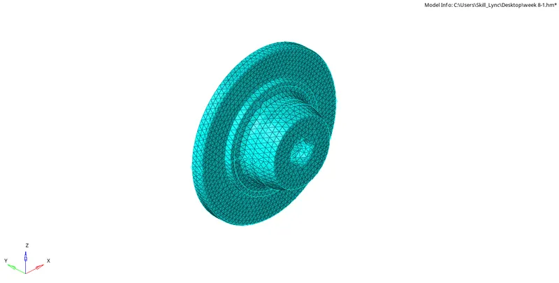
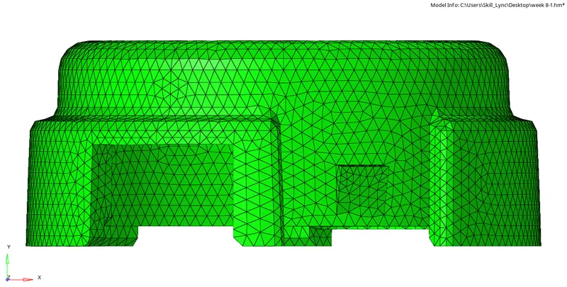
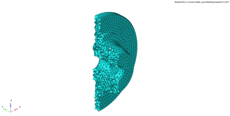
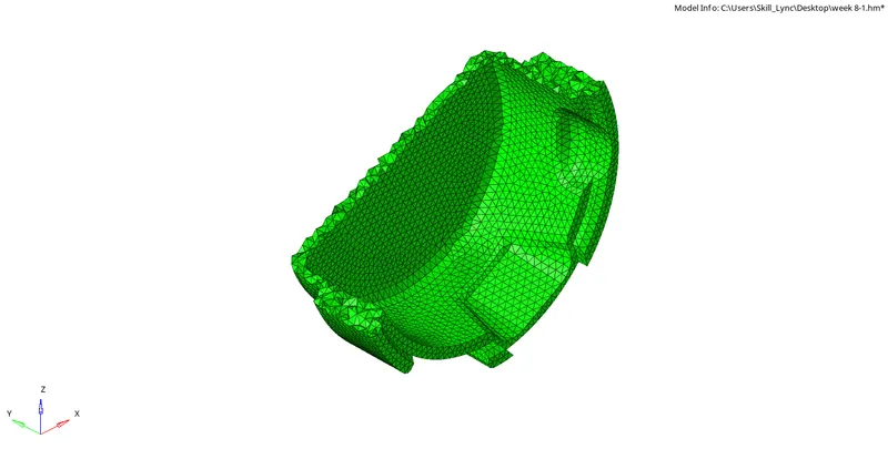
FINAL MODEL:
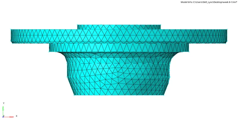
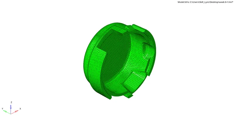
RESULT:
3d meshing done for the given components with,
Element size: min length: 2mm, max length: 7mm, target element: 5mm
Tet collapse: 0.15
MODEL 2:
AIM:
To do 3D meshing of the given components,
with target element size: 6mm
Tet collapse: 0.15
CAD MODEL:
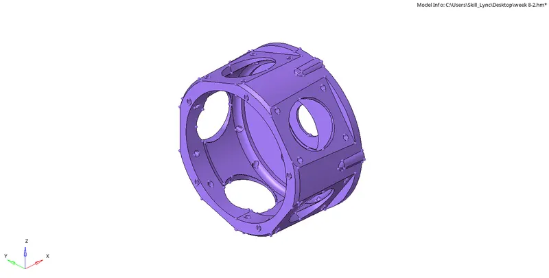
PROCEDURE:
step 1: Geometry cleanup
The geometry cleanup is done using quick edit tool from geometry.
The unwanted lines can be toggled using toggle edges option from quick edit tool.
New lines are plotted according to the mesh convenience using split surface node or split surface lines option from quick edit tool in geometry.
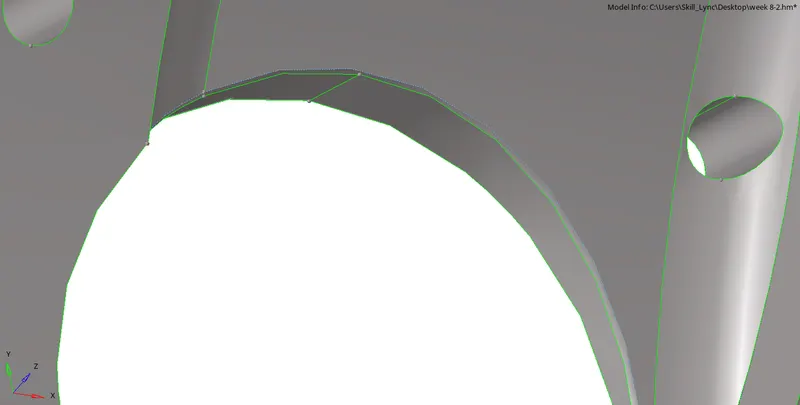
step 2: Creating 2D shell elements
- In order to create 2D shell elements, select the surface that needs to be meshed from automesh option in 2D tool.
- Make sure that criteria file has been set.
- Make sure that only tria elements are used for meshing.
- this can be set from preference option on top centre menu of the screen.
- Since only max and min length is given, untick all other options other than max and min length.
- Going surface by surface create the shell elements for the entire surface.
- Some elements may fail for minimum and maximum length. This can be cleared by undergoing remesh and splitting the elements.
- Some quad elements may form due to the splitting of tria elements. These quad eolements can be cleared by remeshing again.
- Thus all the errors can be cleared.
Step 3: converting to 3D tetra mesh
- for converting to 3D elements, make sure that the criteria and parameter files are set according to the provided values.
- For this, go to 3d bar and select tetra mesh parameter.
- given min and max size, (tick for fill void,fill mid nodes,smoothing) and also provide the value for tetcollapse.
- Go to tetra mesh and select the elements and click on mesh.
- Mask the elements and check to make sure that tetra mesh has been conducted succesfully.
- Click on F10 to check for tetcollapse error.
- failed elements for tetcollapse can be cleared by doing remesh and also using translate option by reverse masking the only failed elements with adjacent elements.
- Thus a zero error 3D mesh can be obtained.
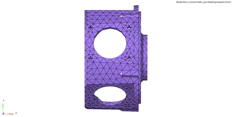
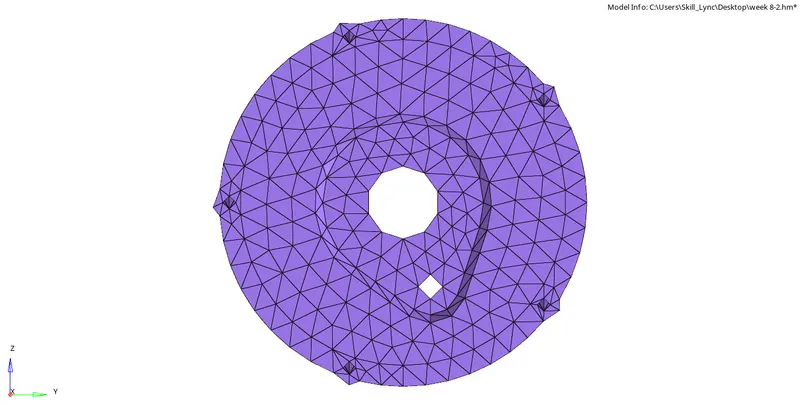
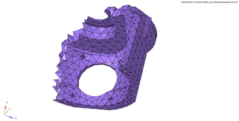
FINAL MODEL:
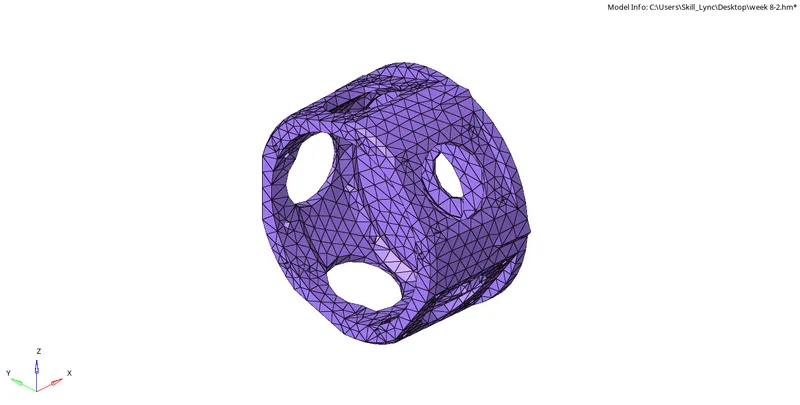
RESULT:
3d meshing done for the given components with,
target element: 6mm
Tet collapse: 0.15
MODEL 3:
AIM:
To do 3D meshing of the given components,
with target element size: 6mm
Tet collapse: 0.15
CAD MODEL:
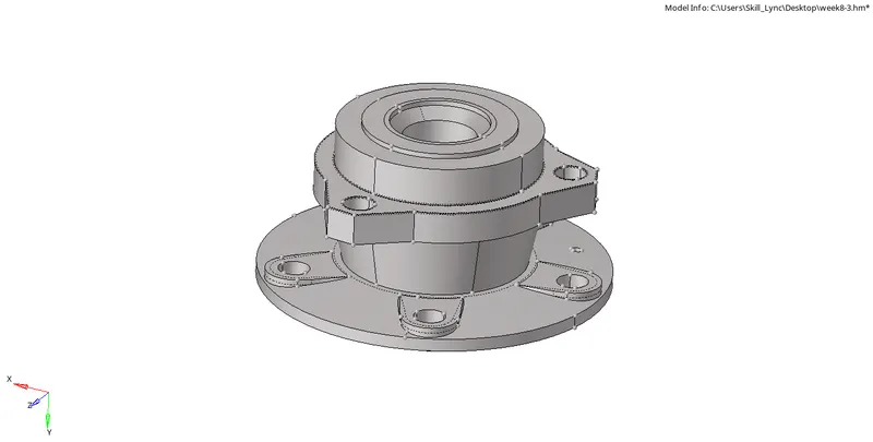
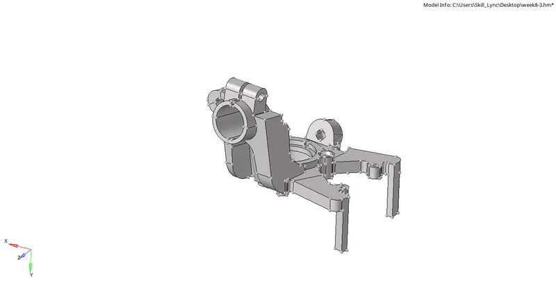
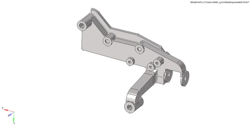
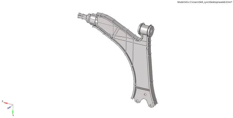
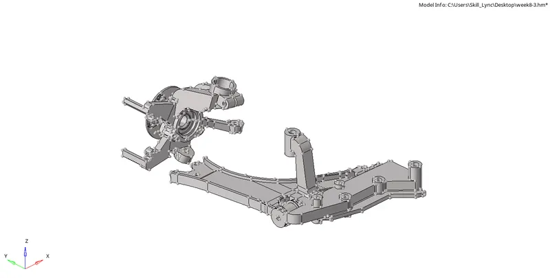
There are 4 components attached together.
PROCEDURE:
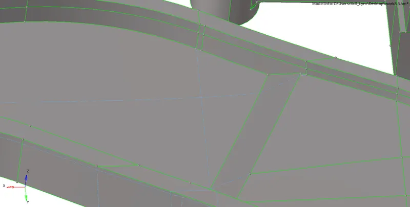
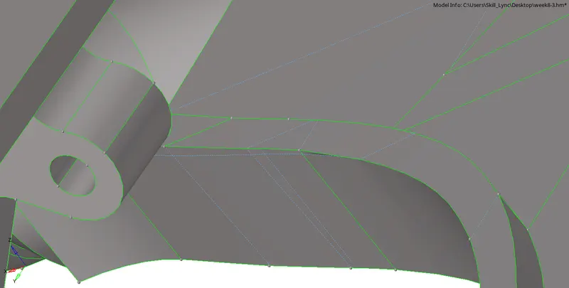
step 1: Geometry cleanup
The geometry cleanup is done using quick edit tool from geometry.
The unwanted lines can be toggled using toggle edges option from quick edit tool.
New lines are plotted according to the mesh convenience using split surface node or split surface lines option from quick edit tool in geometry.
step 2: Creating 2D shell elements
- In order to create 2D shell elements, select the surface that needs to be meshed from automesh option in 2D tool.
- Make sure that criteria file has been set.
- Make sure that only tria elements are used for meshing.
- this can be set from preference option on top centre menu of the screen.
- Since only max and min length is given, untick all other options other than max and min length.
- Going surface by surface create the shell elements for the entire surface.
- Some elements may fail for minimum and maximum length. This can be cleared by undergoing remesh and splitting the elements.
- Some quad elements may form due to the splitting of tria elements. These quad eolements can be cleared by remeshing again.
- Thus all the errors can be cleared.
Step 3: converting to 3D tetra mesh
- for converting to 3D elements, make sure that the criteria and parameter files are set according to the provided values.
- For this, go to 3d bar and select tetra mesh parameter.
- given min and max size, (tick for fill void,fill mid nodes,smoothing) and also provide the value for tetcollapse.
- Go to tetra mesh and select the elements and click on mesh.
- Mask the elements and check to make sure that tetra mesh has been conducted succesfully.
- Click on F10 to check for tetcollapse error.
- failed elements for tetcollapse can be cleared by doing remesh and also using translate option by reverse masking the only failed elements with adjacent elements.
- Thus a zero error 3D mesh can be obtained.
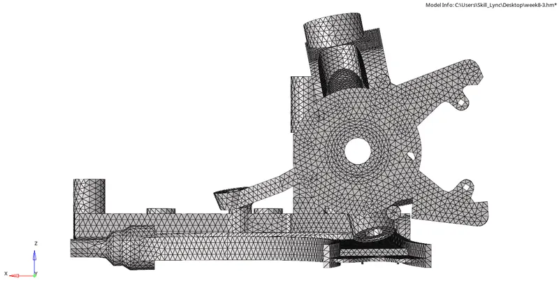
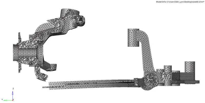
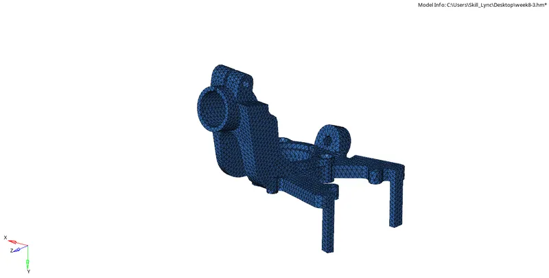
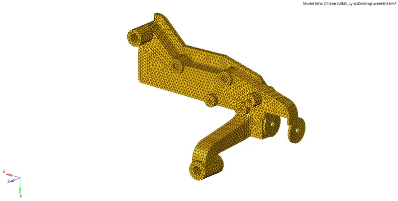
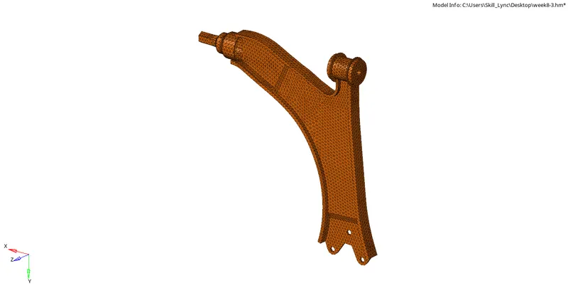
FINAL MODEL:
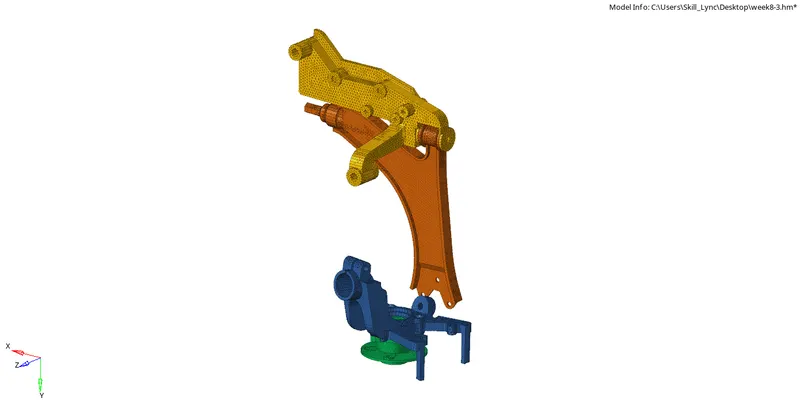
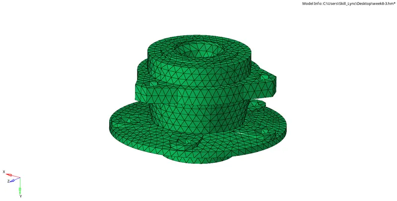
RESULT:
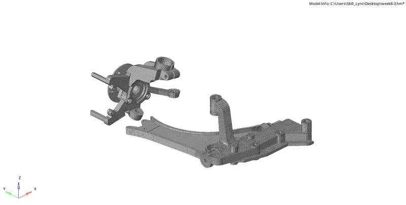
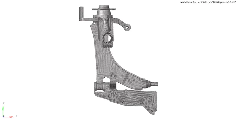
3d meshing done for the given components with,
target element: 6mm
Tet collapse: 0.15