Week 4- Challenge
OBJECTIVE:
To create 1D elements on the following component with given cross-section and DOF.
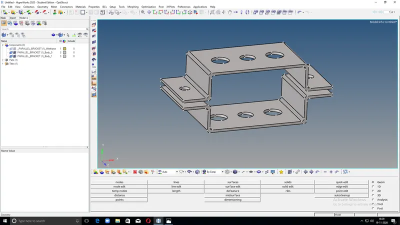
CAD MODEL:
PROCEDURE:
- Import the CAD model
- Apply points on the entire model.
- Convert the model into a wire frame model.
- Go to geometry and select the components to get the midsurface and extract to create a midsurface.
- From component option add a component to not get an ideal or combined surface.
- After adding a component find the midsurface of the down bracket.
- Move the newly created midsurface to the already created component using organise option from tools.
- Mark the surface to be moved and select move option.
- Change in colour occurs resemblance to the already created compound.
- Select material from the top left corner.
- Material details are defined in the down left corner.
- Assign properties for the material and name it.
- Assign properties for all the materials that need to be specified.
- Assign thickness from the down left corner.
- Select properties and card image as opstruct.
- Select the material we are going to use.
- Repeat same procedures for the other component too.
- Mark washersplits around all the holes from quick edit- washersplit option.
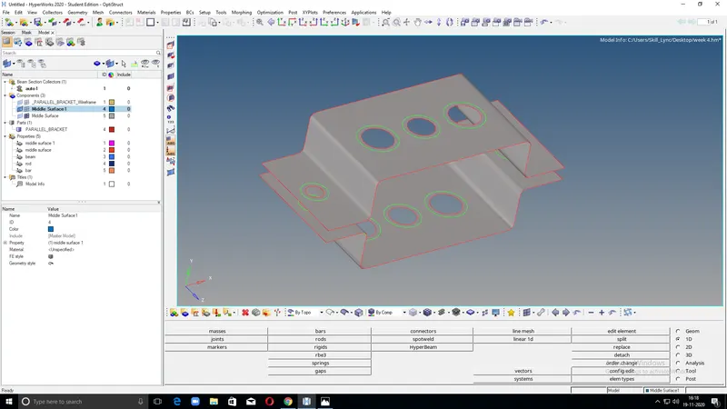
- Provide the offset values
- Select the displayed surface entirely.
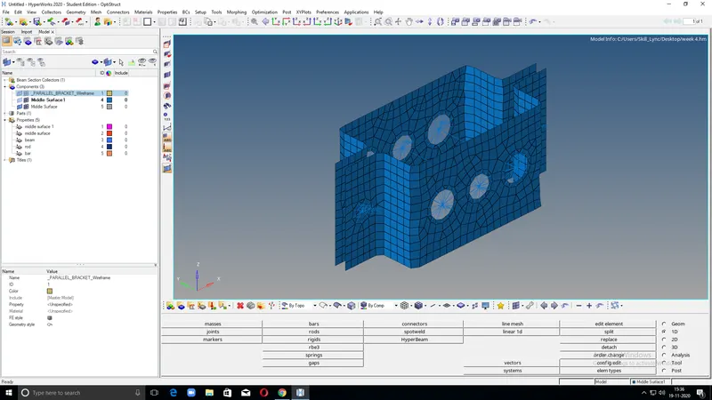
- Select the meshtype as mixed and do the automesh.
- After meshing make the nodes around the washersplits equal.
- Hide the surface.
- Provide RBE2 lync on d and c holes and apply mass of magnitude 10.
- Then provide a,b and c with RBE2,RBE3 and RBE3 lincs with required DOF for each holes.
- Apply spring on f holes from spring option by selecting the required nodes.
- Create beam rod and bar in cross section by selecting create option from standard section in hyperbeam.
- Another screen comes where to create required cross sections by clicking create option-standard section-optistruct or hypermesh.
- Apply the provided dimensions to the cross sections.
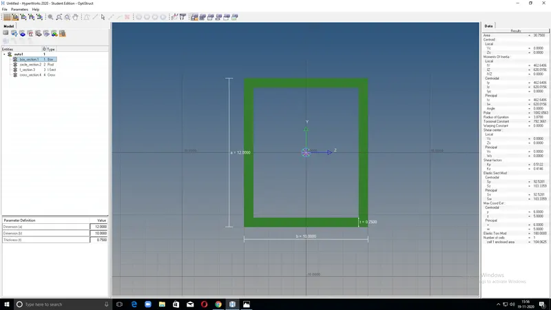
'BOX' cross section
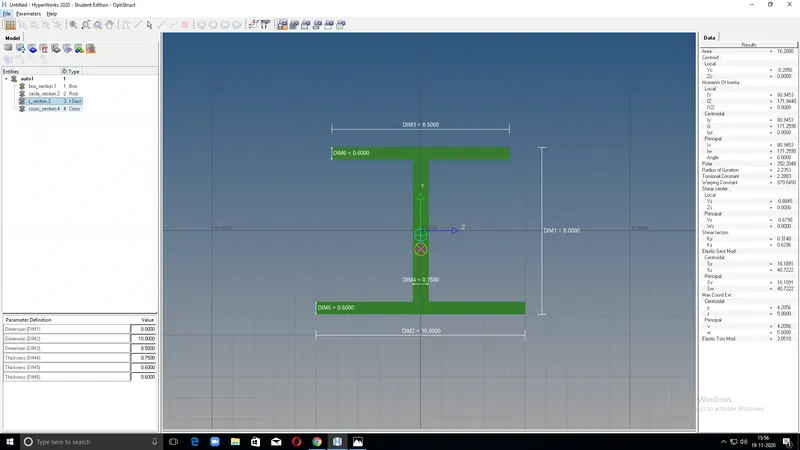
'I' SECTION
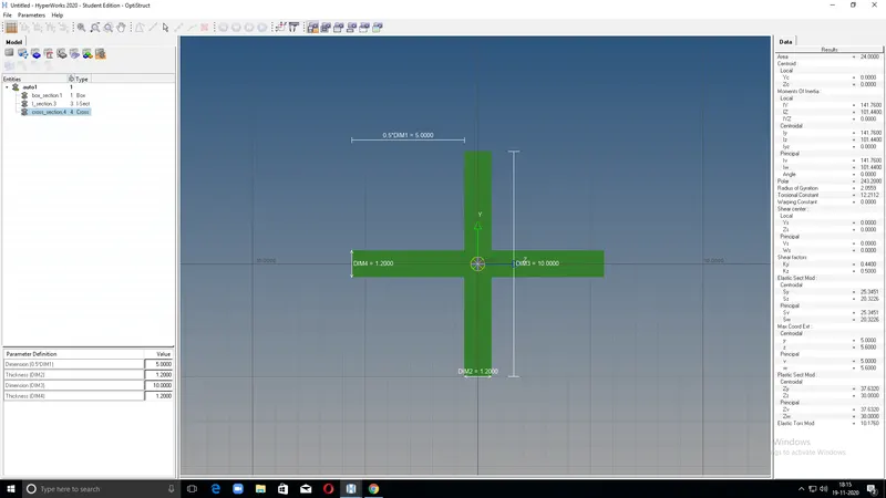
'CROSS' SECTION
- Assign the properties,material,cardimage,cross section and update the model.
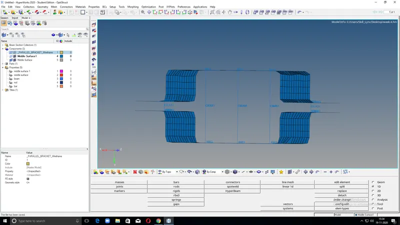
FINAL MODEL:
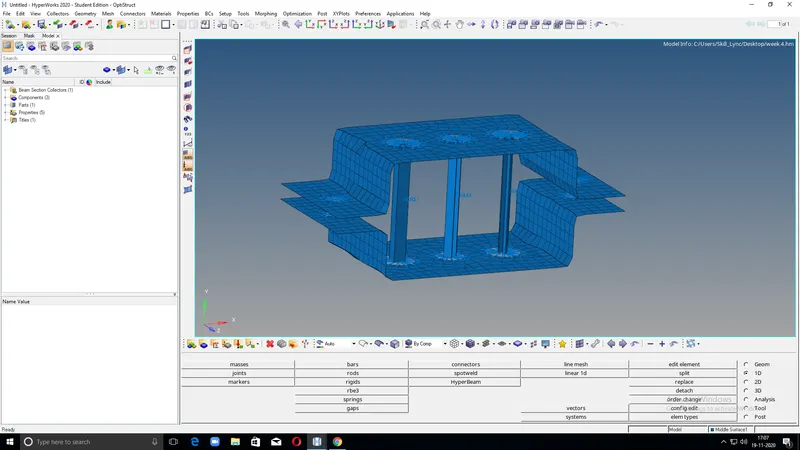
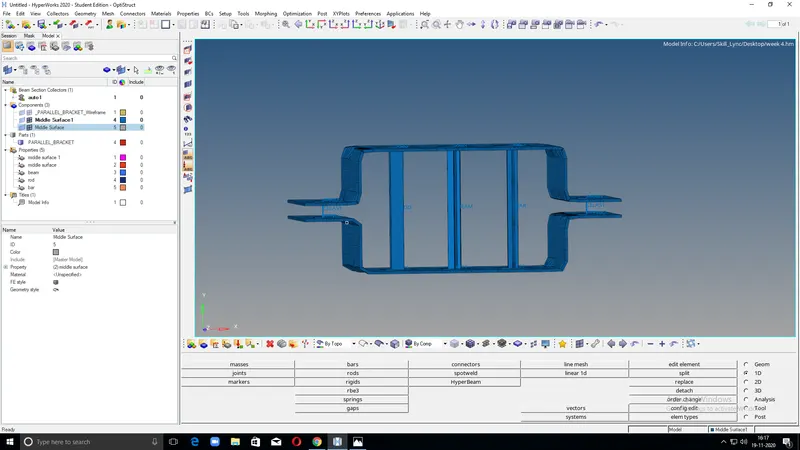
RESULT:
Created 1D element on the given component with following cross-section and DOF.
a. Rod element - with transational DOF and RBE2 link.
Cross section: BOX - Dimension a-12 mm
Dimension b-10 mm
Thickness t-0.75 mm
b. Beam element - with all DOF and RBE3 link.
Cross-section : I section - Dimension a- 8 mm
Dimension b- 10 mm
Dimension c- 8.5 mm
Thickness t1- 0.75 mm
Thickness t2- 0.6 mm
Thickness t3- 0.6 mm
c. Bar element:- with only x and y DOFs With RBE3 link
Cross-section: CROSS section- Dimension DIM1= 5 mm
Thickness DIM2= 1.2 mm
Dimension DIM3= 10 mm
Thickness DIM4= 1.2mm
d & e. applied the mass of magnitude 10 with RBE2 link
f. Joined the two components with Spring elements