Assignment 3-2D Element Formulation Challenge
Aim:- To Compare the results of given crash beam file with base simulation and simulation after improved shell element properties.
Objective:-
* Change the run time of given file to 55 ms.
* Change the number of animation steps during simulation to a minimum of 25 and maximum of 60.
* Run base simulation and simulation after property modification.
* Do the energy error and mass error checks for both case simulation.
* For both case, Plot rigid wall forces, internal energy, hourglass energy, contact energy, total energy of the simulations.
* Give proper explanation for comparing the results for both case's simulation.
Theory:-
Hourglass:
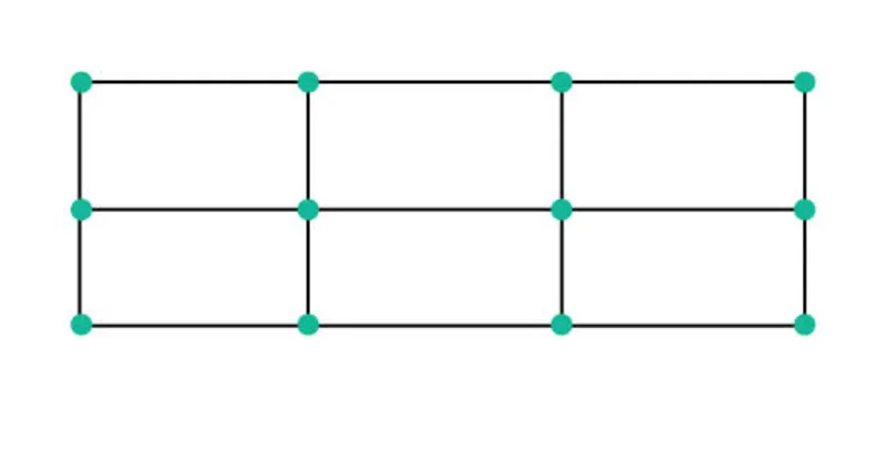
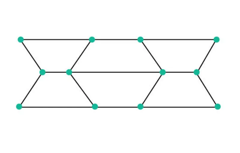
When the elements in a model deform but the strain energy is not computed for that deformation, it results in an Hourglass deformation effect or Hourglass effect. Usually, this can be clearly seen in the post-processing stage where the elements will have a zig-zag formation.
* Normal elements:
* Elements with Hourglass Effect:
METHODS TO CONTROL THE HOURGLASS:-
1. Perturbation method(viscous method)
2. Physical stabilization method (stiffness method)
1. Perturbation method:-
* In Ishell = 1,2,3,4 , the hourglass deformation is detected with motion of the nodes.
* If it is detected , an opposing force is applied on to the node to stabilize the deformation.
* The amount of force inputted is based on the model's material applied like young's modulus, yield stress and plastic tangent.
* This opposing force produces an artificial energy called hourglass energy.
* One isadvantage is that Q4 elements fail in case of large rotation and elestic loading-unloading cycles.
2. Physical stabilization method:-
* In this method, the stiffness is getting added right from the material level. This will have a large effect on our component.
* It is recommended for fewer velocity problems.
* used for QEPH elements.
* Less amount of hourglass energy is needed. Because it is going to be controlled before it arises.
* Advantage over Q4 element is that it works perfectly well at all kinds of loading- unloading cases.
Procedure:-
CASE:1-
* Select Radioss from the user interface menu.
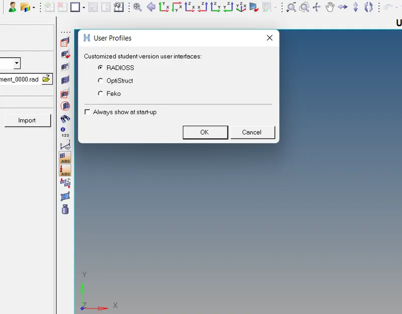
Import the file:-
* For importing, click on Import - Import Solver Deck - Choose the starter file - Import.
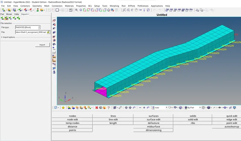
1. Change the run timeto 55 ms
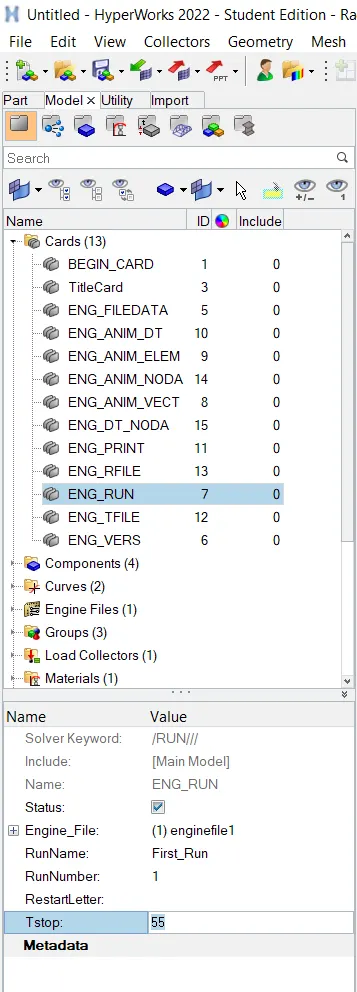
* For changing run time we open model browser and click on cards - ENG_RUN card -> Set the value of Tstop= 55.
2. Change the number of animation steps during simulation to a minimum of 25 and a maximum of 60
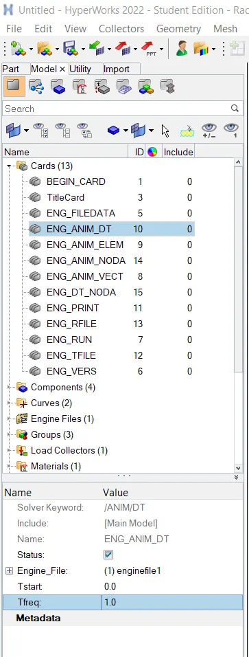
* To get the animation steps within a certain number, we need to alter the Tf value in the model.
* We know that,
Tf = Run Time / Number of animation steps
= 55/55
= 1
3. Run the base simulation without any modification to element properties.
* Go to analysis - Radioss.

* Check include connectors box.
* Type ' -nt 4 ' in options.

* Save file in specific folder.
* Click on Radioss.
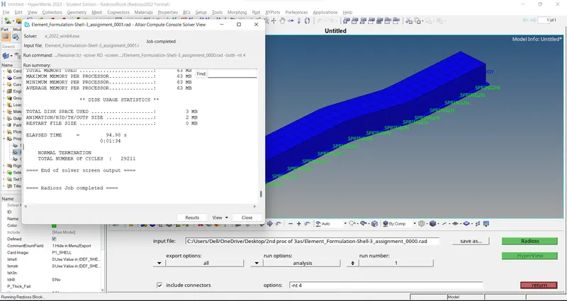
* After the simulation is completed solver tab is open as we can see in above image.
4. At the end of the simulation, do the energy error and mass error checks and determine whether results would be acceptable.
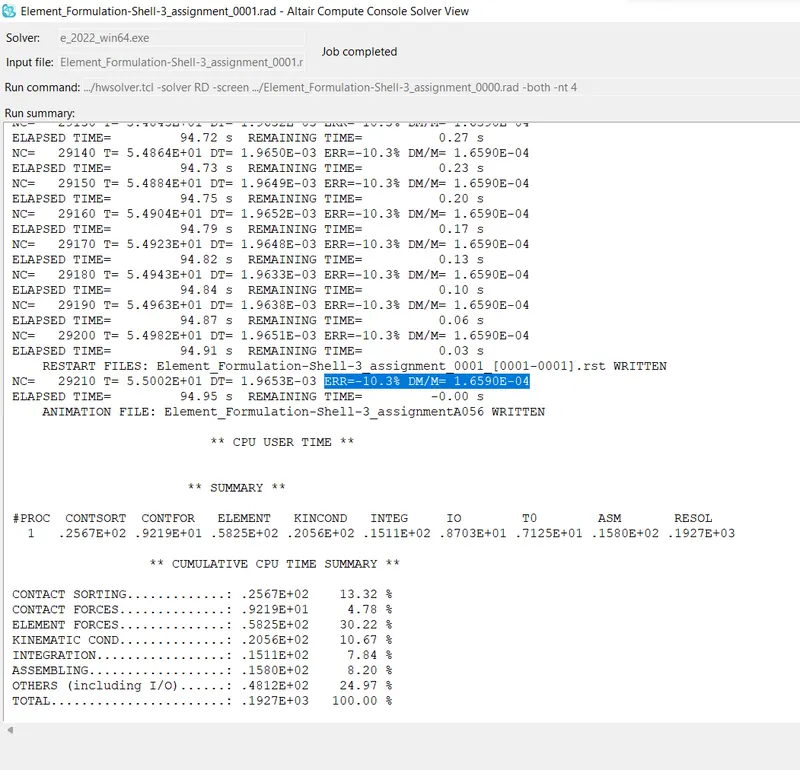
* From the above image, we can see that the Energy error ranges from 0% to -10.3% and mass added is constant at 1.659E-04 which is well within the acceptable range.
5.Plot rigid wall forces, internal energy, hourglass energy, contact energy, total energy of the simulations.
* First we open Hyper view in new window and load the simulaiton h3d file.
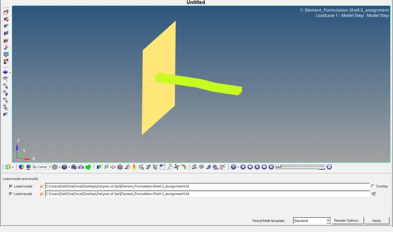
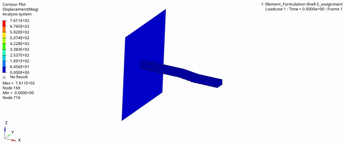
* To see the animation and deformation in the material with respect to displacement, click on HyperView window - Select the .h3d file - Contour - Result type(v) - Displacement - Apply.

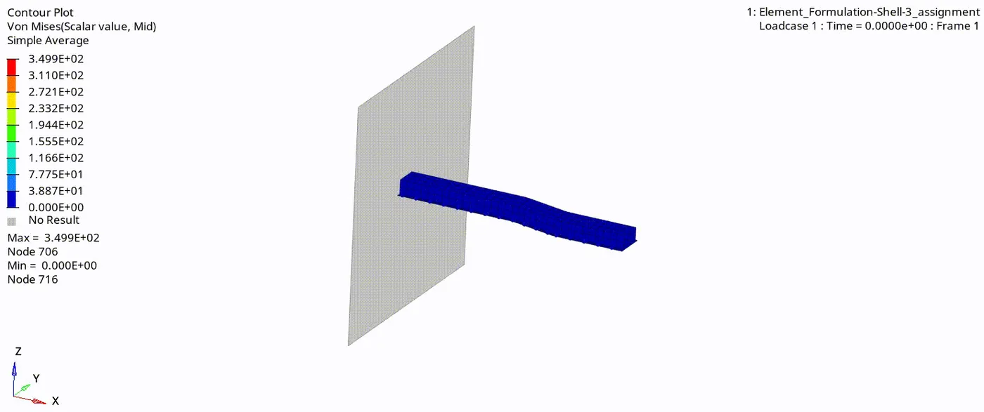
* To see the animation and deformation in the material with respect to Von Mises stress, click on HyperView window - Select the .h3d file -Contour -> Result type(v) - Von Mises - Averaging method=Simple -> Apply.

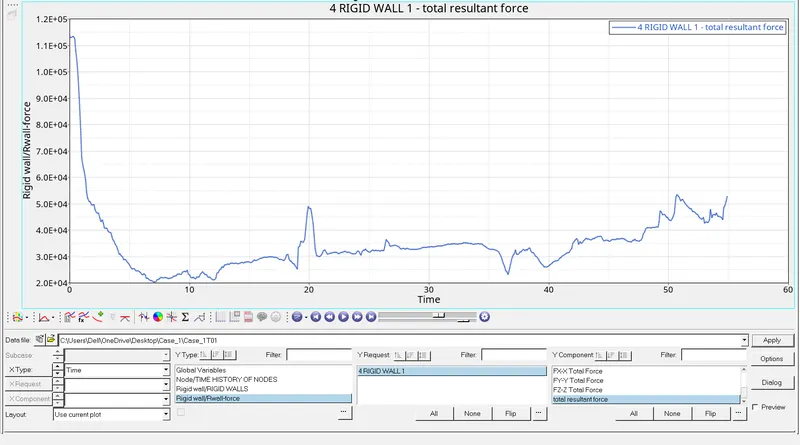
* To plot the graphs, click on HyperGraph 2D window - Select the T01 file
* Rigid wall force -
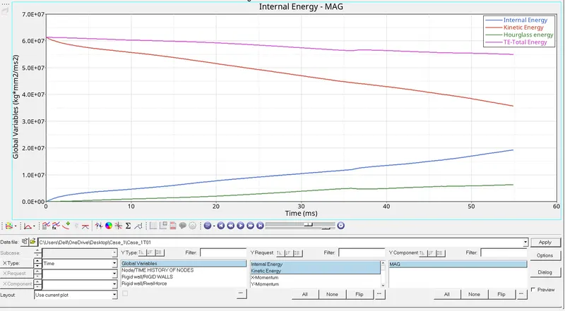
* Internal energy, kinetic energy, hourglass energy, , total energy
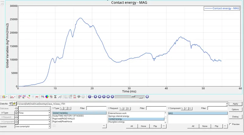
* contact energy
CASE:2-
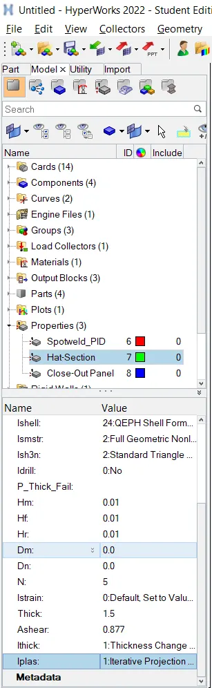
Recommended properties:
| Parameters | Comment | |
|
Ishell =24 |
QEPH 4 nodes shells are best combination of cost and accuracy. | |
|
Ismstr=2 |
Full geometric nonlinearities (default)with possible small strain formulation activation in RADIOSS Engine. | |
|
Ish3n=2 |
Standard 3 noded shell (C0)with modification for large rotation(default) |
|
| N=5 | Number of integration points set to 5 for accuracy bending. | |
|
Ithick=1 |
Thickness change is taken into account for accuracy. |
|
|
Iplas=1 |
Iterative plasticity for good accuracy. |
* Change the property card as per recommended values.
* For changing the property we click on Model browser - Property folder - Select Hat-Section - Go to the Propert card and change the parameters to the recommended properties. -
Run the simulation with modification to element properties.
* Go to analysis - Radioss.
* Check include connectors box.
* Type ' -nt 4 ' in options.
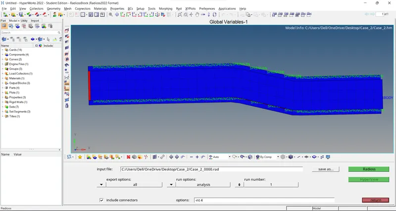
* Save file in specific folder.
* Click on Radioss.
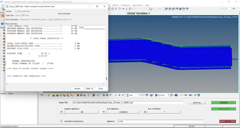
* After the simulation is completed solver tab is open as we can see in above image.
At the end of the simulation, do the energy error and mass error checks and determine whether results would be acceptable.
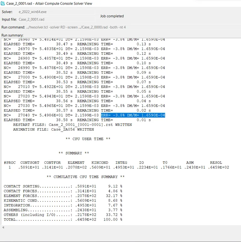
* From the above image, we can see that the Energy error ranges from 0% to -3.8% and mass added is constant at 1.659E-04 which is well within the acceptable range.
Plot rigid wall forces, internal energy, hourglass energy, contact energy and the total energy of the simulations
* First we open Hyper view in new window and load the simulaiton h3d file.
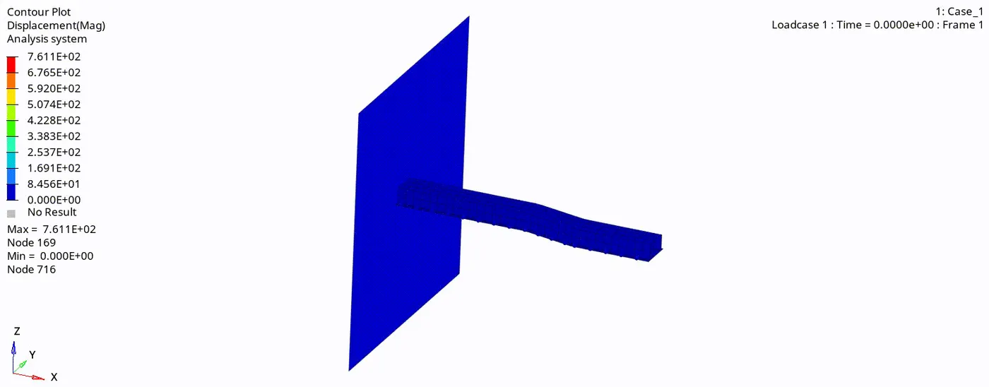
* To see the animation and deformation in the material with respect to displacement, click on HyperView window - Select the .h3d file - Contour - Result type(v) - Displacement - Apply.
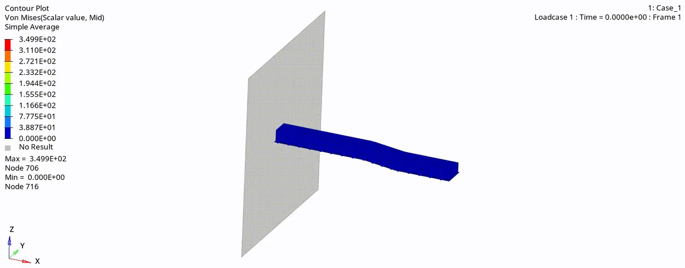
* To see the animation and deformation in the material with respect to Von Mises stress, click on HyperView window - Select the .h3d file -Contour -> Result type(v) - Von Mises - Averaging method=Simple -> Apply.
* To plot the graphs, click on HyperGraph 2D window - Select the T01 file
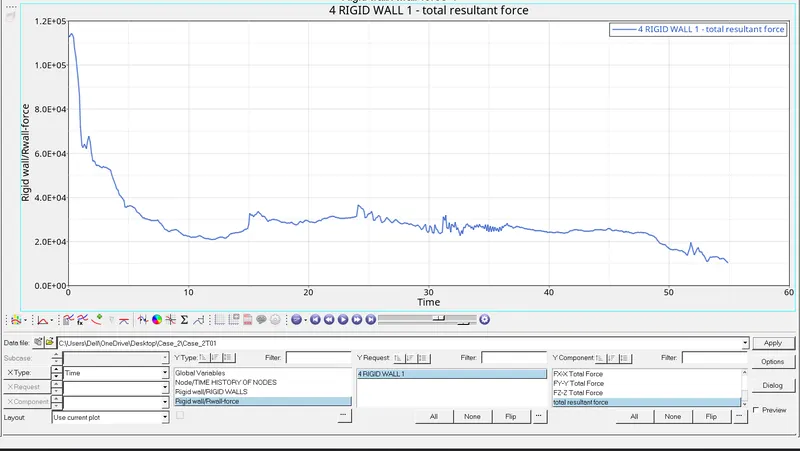
* Rigid wall force -
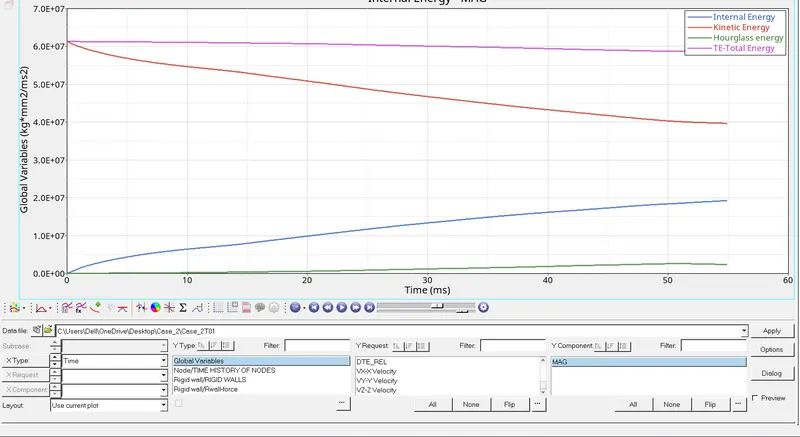
* Internal energy, kinetic energy, hourglass energy, , total energy
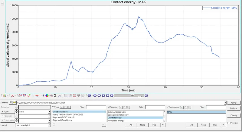
* contact energy
Result:-
* Comparision of plots of both cases:-
Case-1 ( simulation before modified property card ) Case-2 ( simulation after modified property card )
1. Energy ( Internal, Kinetic, Hourglass, total )
2. Contact Energy
3. Rigid wall forces
* From above comparision we can observed that hourglass energy of case 2 is very less as compared to case 1 because, we use QEPH reduced integration element which has physical stabilization method for controling hourglass effects.
* From above comparision we can observed that total energy is more constant in case 2 as compared to case 1.
* We observed that Rigid wall force is less at the end of simulation in case 2 as compared to case 1.
* Internal energy is lesser than Kinetic Energy due to energy error.
* From above image we can observe that Energy error is reduced from -10.3% to -3.8% by using the recommended properties.
Conclusion:-
We change run time and animation steps for given crash beam file and run simulation with base property values and modified property values successfully and we observed the results of both cases and find that simulation after modified property card gives us more accurate and satisfactory results.