Assignment 3-2D Element Formulation Challenge
AIM:
- To run the simulation for given component with and without changing the recommended element parameters using radioss solver
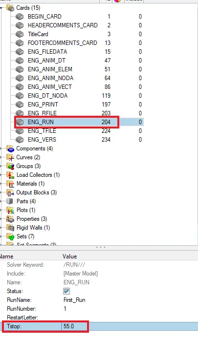
1.Using the crash beam file from the previous assignment, change the run time to 55 ms
- we need to set Tstop value as 55 which is called run time
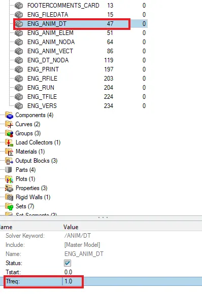
2. Change the number of animation steps during simulation to a minimum of 25 and maximum of 60.
- open ENG_ANIM_DT file and Tfreq value
- time step is 55
- so Tfreq = runtime/no of animation step
- 55/55 = 1 therefore Tfreq= 1
3. Run the base simulation without any modification to element properties.
- keep the element property as default
- now run the simulation in radioss
- check include connectors and options as -nt 4

- then save this 000.rad file as desired location as case-1
- after click radioss then it will start the simulation
- new popup will come and weit until finish the simulation
- open the enginefile(0001.rad)file and verify Tfreq and Tstop values
- we can see numbers of animation step as 56
4. At the end of the simulation, do the energy error and mass error checks and determine whether results would be acceptable.
- we can accept range for a ENERGY ERROR -15% TO +5% , MASS ERROR is 0 to 2%
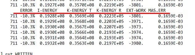
- maximum energy error = -10.3%
- maximum internal energy error = 0.1933E+08
- maximum kinatic energy error = 0.3562E+08
- maximum mass energy error = 0.1659E-03
5. If acceptable, Plot rigid wall forces, internal energy, hourglass energy, contact energy, total energy of the simulations.
Postprocessing
case-1
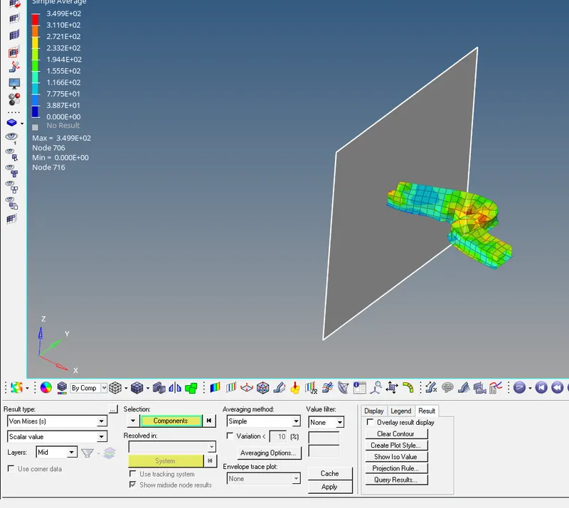
- review the simulation using hyperview
- split the screens
- openhyper view in second window and import h3d file
- open in countour form
2.plot hypergraphs
- divide more screens
- go to hypergraph 2d then plot each graphs

- this way we can plot each graph
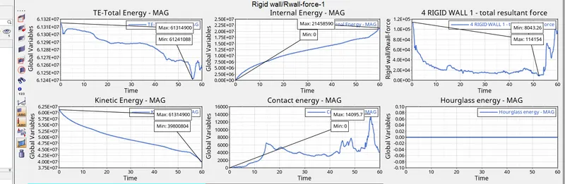
- kinetic energy
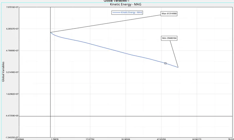
- kinetic enrgy decreases from t=0 to end
- it decreases due to decreases in velocity after initial moment
- where rail start deforming sp there will be a energy restore
- at the end of deformation kinetic energy value become zero
- at that point kinetic energy attain maximum minimum value
2.Internal energy
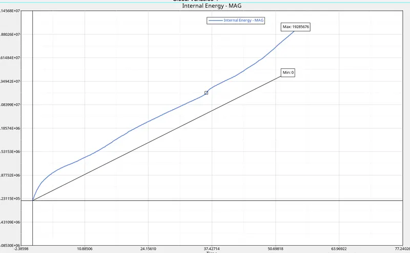
- at t= zero internal energy also zero then gradually increases
- internal energy I= Q + W
- we can neglet Q there is no heat transfer
- W= F X D
- internal energy increases due to deformation occur
3. CONTACT ENERGY
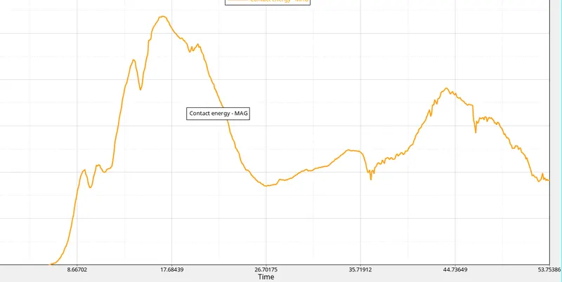
- initially there is no contact between rail component and rigid wall so initially it is zero
- when component starts hitting wall contact energy increases
- when displacement or deformation occurs contact energy increases
4.hourglass energy
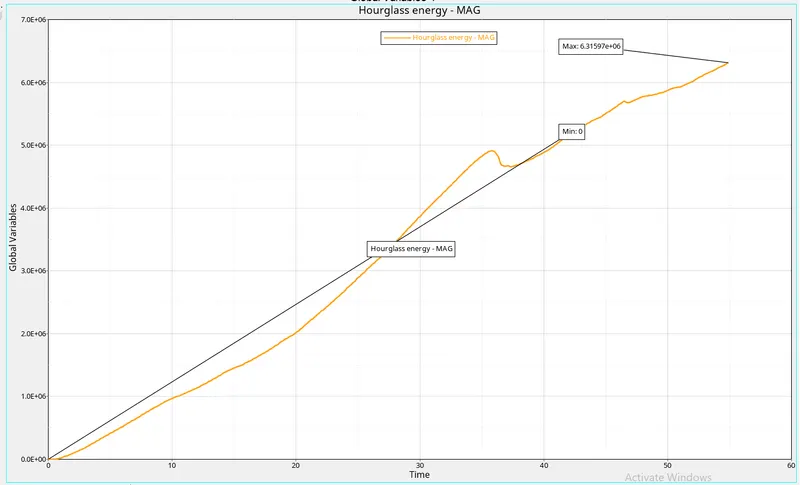
- here hourglass energy starts from initial postion because no reccomneded parameter is applied
- to balance rest energies hourglass we need a artificial energy called hourglass energy and goes increasing
5.rigid wall forces
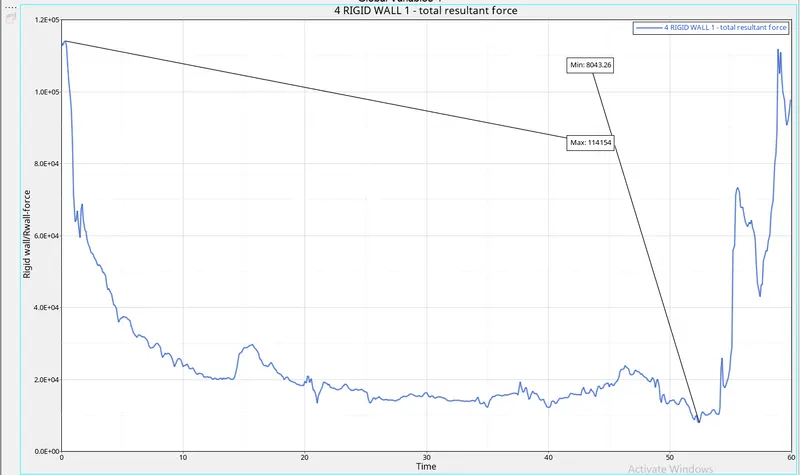
- here rigid wall forces is at higher value in beginning
- because solver doesint recoed the time
- when rail component hits the wall it increases in begginging and then decreasing beacause it hits the rigid wall while deformation happens
6.total energy
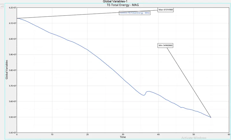
- total energy = sum of KE+IE+CE+HE
- initially it is in increased condition beacuse it is sum of all energies
- only kinetic energy is increased value in intial postion
- kinetic energy is direclty propotional to total energy
- due to 10.3% energy error it decreasing from initial point to so on
case-2-with assigning recomended properties
- now we assign recommended properties to hat section and close out panel as per given above
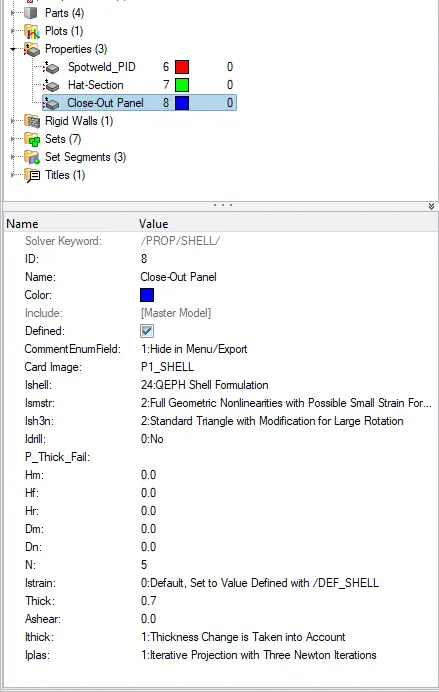
- then again run the simulation were we need to save in sapprate folder
- then run the simulation by radioss
- if we check engine output file there is also impovment in energy errors
- after we need to view in hyperview
- then we need to plote every graph (steps same described in case-1)
hourglass energy
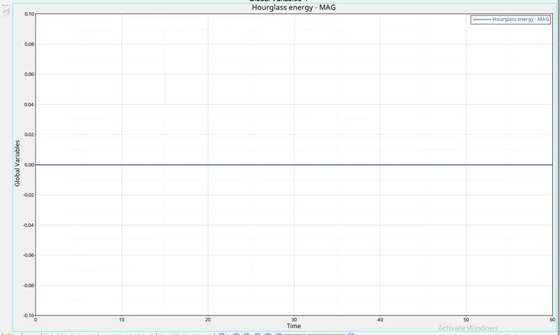
- IN CASE-2 there is no hurglass effect beacause we applied recommneded parameters with fully integrated methode in case-1 we used reduced ingration methode so there is houglass effect happened , by changing element formulation in case-2 we eliminated hourglass effect
- if we look in both contour models in both cases we can nottice there is a element distortion in case1 due to hourglass effect and it is not seen in sencond case
-
Ishell =24
QEPH 4 nodes shells are best combination of cost and accuracy. is used in case -2 - QEPH is improved under integrated methode
- hourglass energy limit is 10% of internal energy
remining graph s in case2
comparison of case-1 and case-2
| characterstics | case-1 | case-2 |
| maximum energy error | 10.3% | -0.1% |
| maximum kinetic energy error | 0.3562E+08 | 0.3970E+08 |
| maximum internal energy error | 0.1933E+08 | 0.2156E+08 |
| total energy error | total energy increases and slightly decreases due to energy error | no change in total energy |
| hourglass energy error | hourglass energy increases due to all other energies | hourglass energy remains contant due to applying recomended parameter |
RESULT:
- simulation run with and without assigning recomended parameters
- graph plotted for both condition
- compared both graphs and analysed the result