Assignment 3
Questions:
Comparison of results with base simulation and improved shell element properties
- 1. Using the crash beam file from the previous assignment, change the run time to 55 msec.
- 2. Change the number of animation steps during simulation to a minimum of 25 and maximum of 60.
- Run the base simulation without any modification to element properties.
- 4. At the end of the simulation, do the energy error and mass error checks and determine whether results would be acceptable.
- 5. If acceptable, Plot rigid wall forces, internal energy, hourglass energy, contact energy, total energy of the simulations.
- 6. Change all the shell elements properties to recommended properties, save this as separate, rad files and run the simulation.
- 7. Follow steps 5 and 6.
- 8. Create a brief report comparing all the results from steps 5 and 6 for both simulations.
- 9. Comment whether there is any change in the results and why there is any change in the result.
Solution:
The model in consideration is shown below.
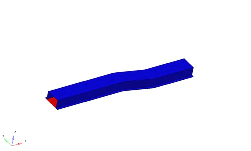
Figure ‑1 The model in consideration
The run time is to be changed from 60msec to 55msec, as per the objective as illustrated in the figure below. The animation step is also to be changed to 2.2msec (55/25) using the ‘Tfreq’ from the ‘ENG_ANIM_DT’.
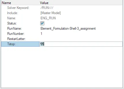
Figure ‑2 ENG_RUN Card
After the run time is changed, the model is run as it is using the ‘analysis’ feature. The process takes a few seconds to run. The calculation progress is checked through the ‘Hyperworks Solver View’. The job completion indicates to check the error in the energy and mass. Figure -3 indicates the error in energy and mass, which comes out to be -10.3% and 0.1659E-3 respectively, at the end of 54.98 msec. The negative sign indicates the loss of energy and as the energy error is more than -15% the value is acceptable.

Figure ‑3 Table indicating error wrt. time-step
The figure below shows the variation of the energies and forces with time.
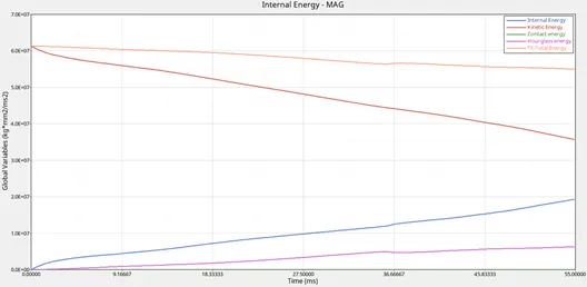
Figure ‑4 The variation of energies with time in msec.
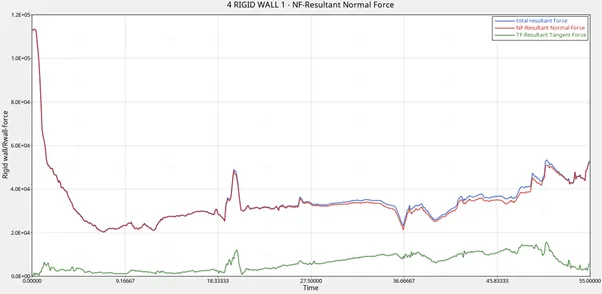
Figure ‑5 Variation of Forces with time in msec.
The shell element properties are modified in the ‘Property’ tab, as illustrated below.
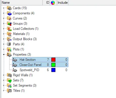
Figure ‑6 The Properties needed to be modified
The modified properties are illustrated below in the figure.
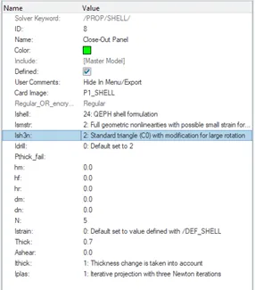
Figure ‑7 The parameters
The simulation is run again and checked for the errors in energy and mass, which comes out to be -0.1% and 0.1659E-3 respectively, and is illustrated below.
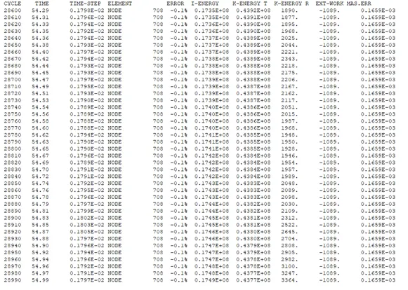
Figure ‑8 Table of errors with respect to time-step
The energies and forces for the modified properties with respect to time for both cases are illustrated below.
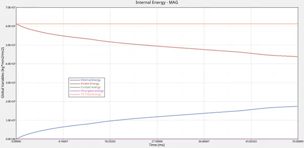
Figure ‑9 The variation of energies with time in msec.
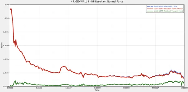
Figure ‑10 Variation of Forces with time in msec.
The comparison of energies and forces between the two cases is depicted below.
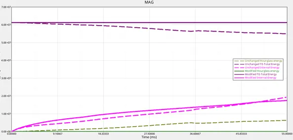
Figure ‑11 Comparison of energies for both the cases
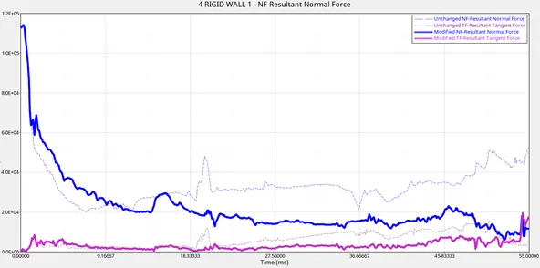
Figure ‑12 Comparison of forces for both the cases
The total energy in the case of 'QEPH' element due to its property of reducing the hourglass effect, is constant, as compared to the unaltered version. The contact energy is similar for both the cases, while both curves are increasing, but the internal energy is higher in the case of the QEPH element. The forces in 'QEPH' element are relatively low, as compared to the unchanged model, due to the more internal energy.