Assignment 1
Assignment1:
Objective:
- Clean the geometry.
- Extract midsurface.
- Clean midsurface geometry.
- Ignore holes less than dia 5mm.
- Create a 2D mesh with target length 5mm, min 3.5mm max 7mm.
- And assign proper thickness, by creating a generic property.
Solution 1. The model in consideration is depicted in the figure below.
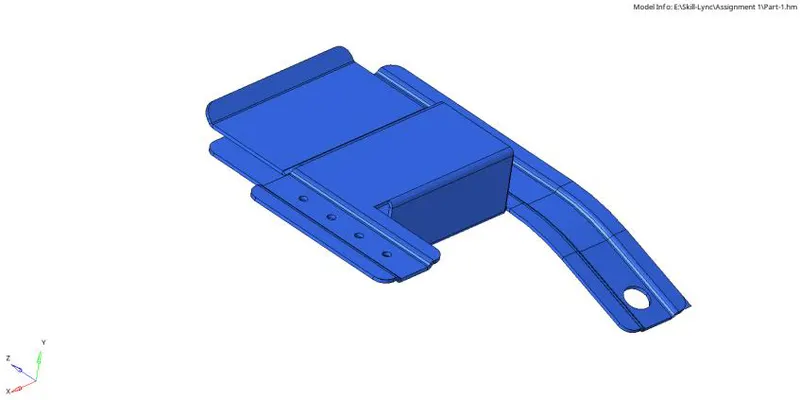
Figure -1 The geometry
For the clean-up of the geometry, free edges, non-manifold edges, and irregularities are to be resolved. The figure below shows the same for the geometry under consideration.
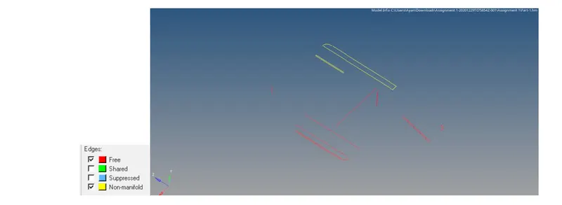
Figure -2 The parts needed to be resolved
The clean-up process includes using toggle edge with the proper tolerance value, followed by generation of surface for any missing surface present and finally deleting the 2 non-manifold edges, as shown in the figure below.
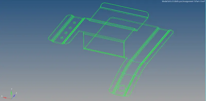
Figure -3 The cleaned up geometry
Now the obtained closed geometry is used to extract the midsurface as depicted in the figure below.
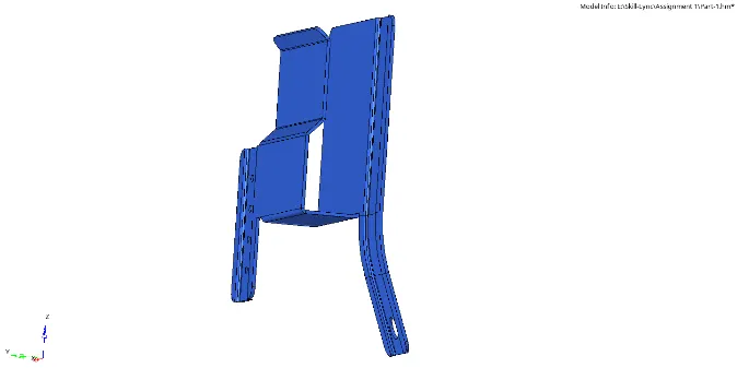
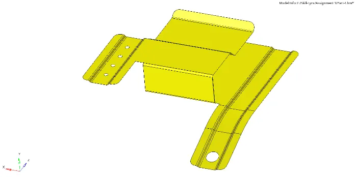
Figure -4 The geometry before midsurface Figure -5 The extracted midsurface
The clean-up for the midsurface starts with defeaturing operation starting with ignoring the holes below 5mm of diameter and then the edge and surface fillets. Figure -7 below depict the cleaned up defeatured midsurface.
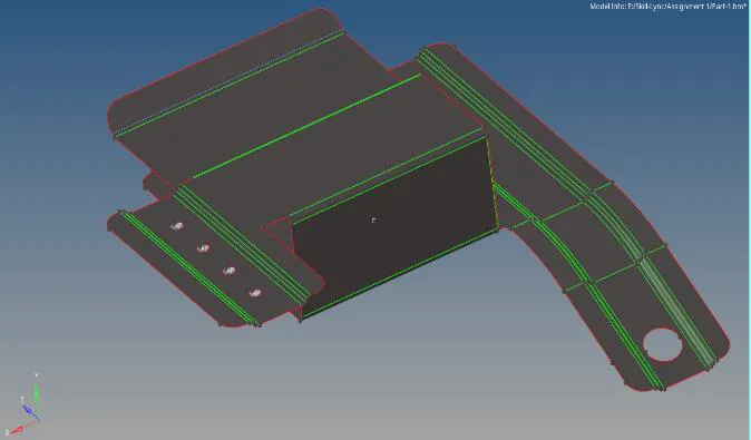
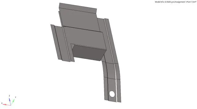
Figure -6 The holes with dia. less than 5mm Figure -7 The defeatured midsurface
After the midsurface is cleaned up, the 2D shell mesh is generated. The initial 2D mesh is generated using automesh, and the figure below depicts so.
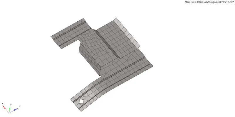
Figure -8 The generated 2D mesh before refinement
The mesh generated needed to be refined. The element quality checks were performed following the table listed in the figure below, in order to obtain the refined 2D shell mesh.

Figure -9 The table enlisting the 'quality check' list
After the quality check, the final mesh obtained is shown in the figure below.
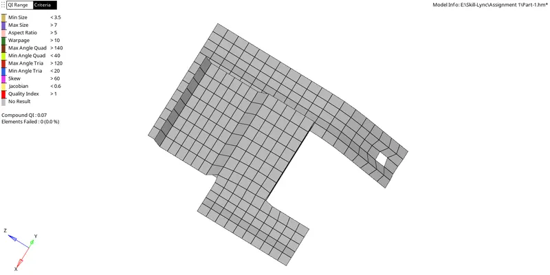
Figure -10 The mesh refinement
The refined mesh was then checked for the element normals which is indicated in Figure -11.
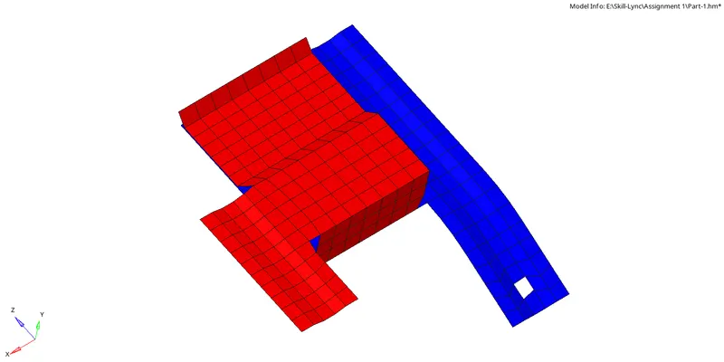
Figure -11 The colourised element normals
The total number of elements counted to be 357 for the above mesh. Then the mesh is assigned a thickness of 2mm to obtain the detailed representation as shown in the figure below.
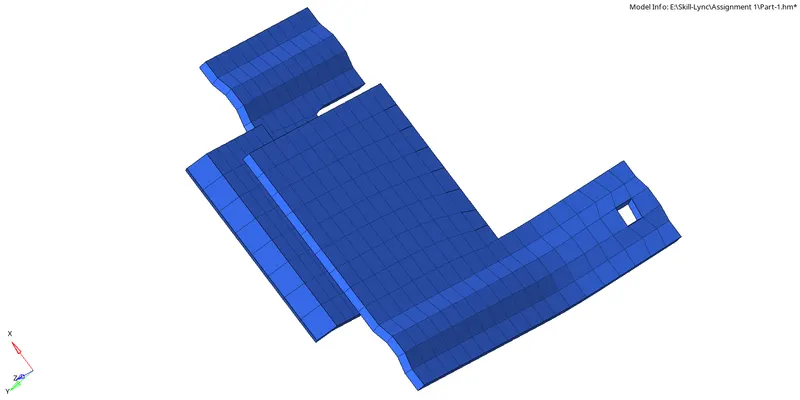
Figure -12 The detailed representation
Solution 2. The model in consideration is shown in the figure below.
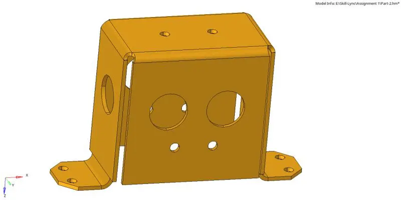
Figure -13 The geometry
The clean-up geometry is illustrated as shown in the figure below.
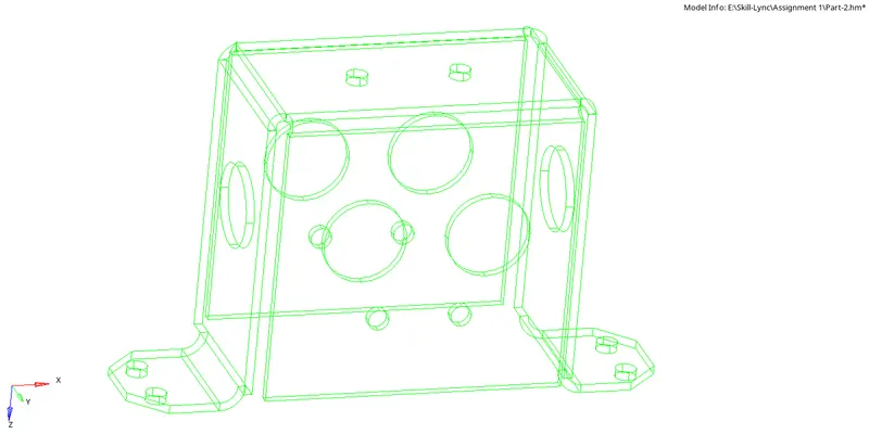
Figure -14 The cleaned up geometry
Now the obtained closed geometry is used to extract the midsurface.
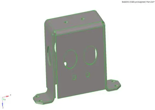
Figure -15 The geometry before midsurface
The clean-up for the midsurface starts with a defeaturing operation, starting with ignoring holes below 5mm of diameter and the surface and edge fillets. The figure below depicts the cleaned-up defeatured midsurface.
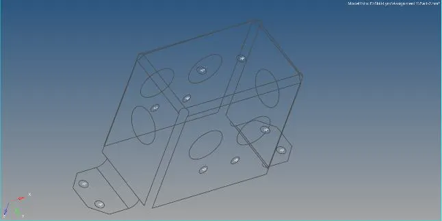
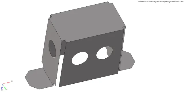
Figure -16 The holes with dia. less than 5mm Figure -17 The defeatured midsurface
After the midsurface is cleaned up, the 2D shell mesh is generated. The initial 2D mesh is generated using automesh, and the figure below depicts so.
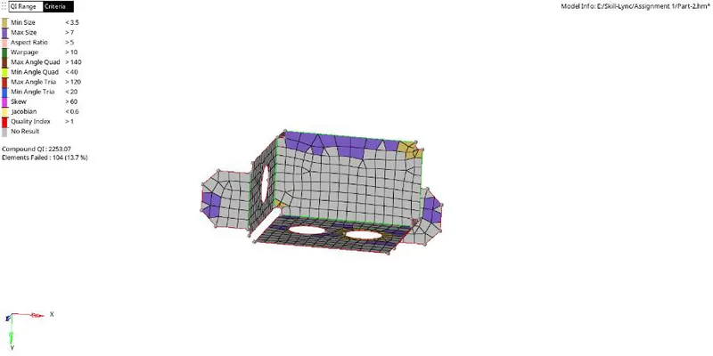
Figure -18 The generated 2D mesh
The mesh generated needed to be refined. The element quality checks were performed following the table listed in the figure below.
Figure -19 The table enlisting the 'quality check' list
After the quality check, the final mesh obtained is shown in the figure below.
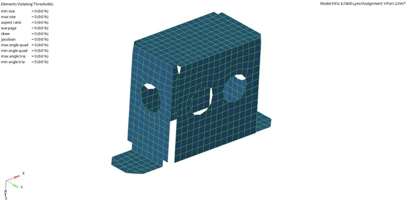
Figure -20 The mesh refinement
The refined mesh was then checked for the element normals which is indicated in the figure below.
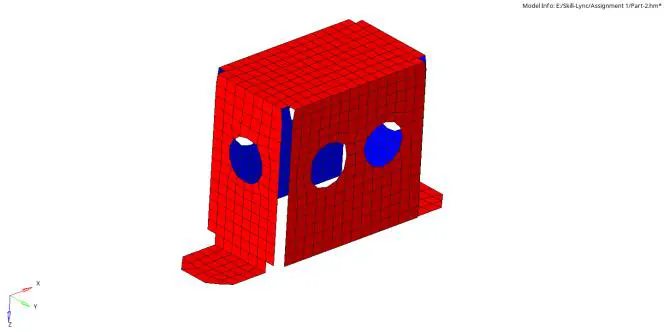
Figure -21 The colourised element normals
Then the mesh is assigned a thickness of 2mm to obtain the detailed representation as shown in the figure below.
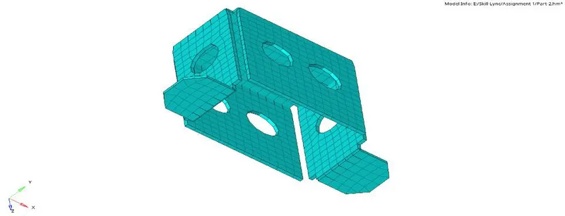
Figure -22 The detailed representation
Solution 3. The model in consideration is depicted in Figure -23.
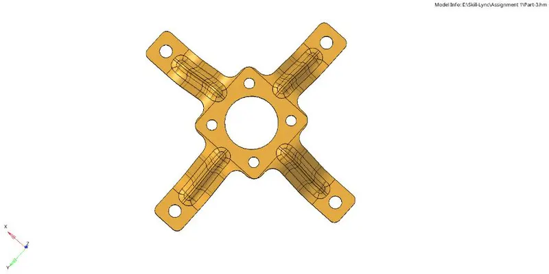
Figure -23 The geometry under consideration
The cleaned-up geometry is shown in the figure below.
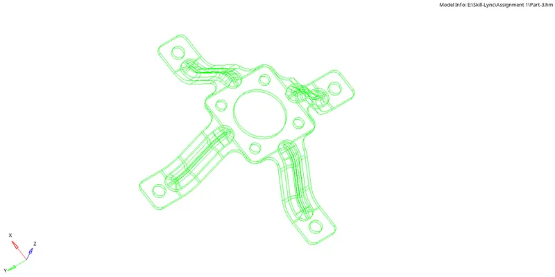
Figure -24 The cleaned up geometry
Now the obtained closed geometry is used to extract the midsurface as depicted in the figure below.
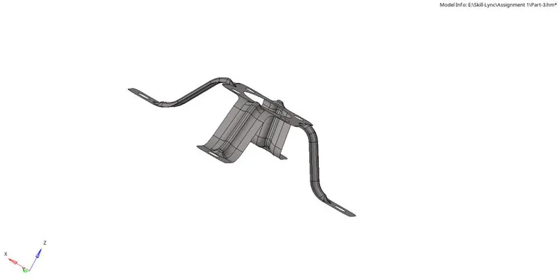
Figure -25 The extracted midsurface
The clean-up for the midsurface starts with a defeaturing operation, starting with ignoring holes below 5mm of diameter and the surface and edge fillets. The figures below depict the cleaned up defeatured midsurface.
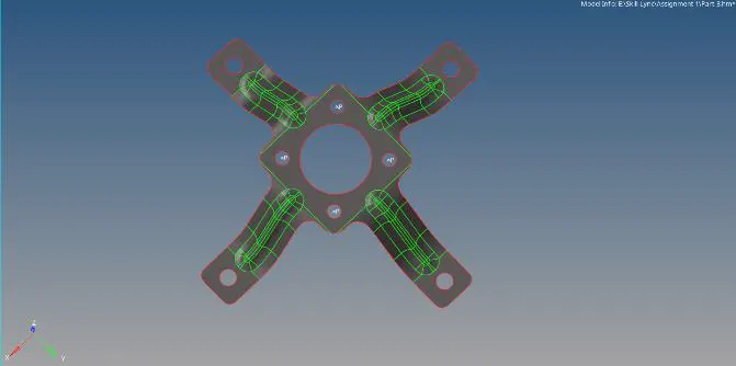
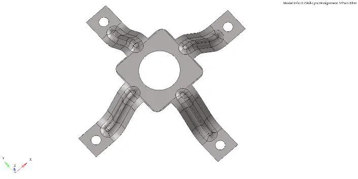
Figure -26 The holes with dia. less than 5mm Figure -27 The defeatured midsurface
After the midsurface is cleaned up, the 2D shell mesh is generated. The initial mesh is generated using automesh, and the figure below depicts so.
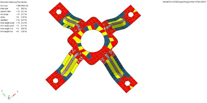
Figure -28 The generated 2D mesh
The mesh generated needed to be refined. The element quality checks were performed following the table listed in the figure below.

Figure -29 The table enlisting the 'quality check' list
After the quality check, the final mesh obtained is shown in the figure below.
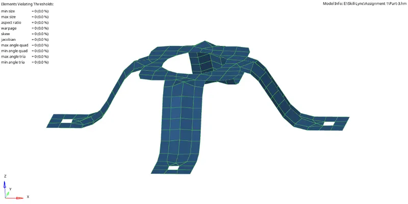
Figure -30 The mesh refinement
The refined mesh was then checked for the element normals which is indicated in Figure -31.
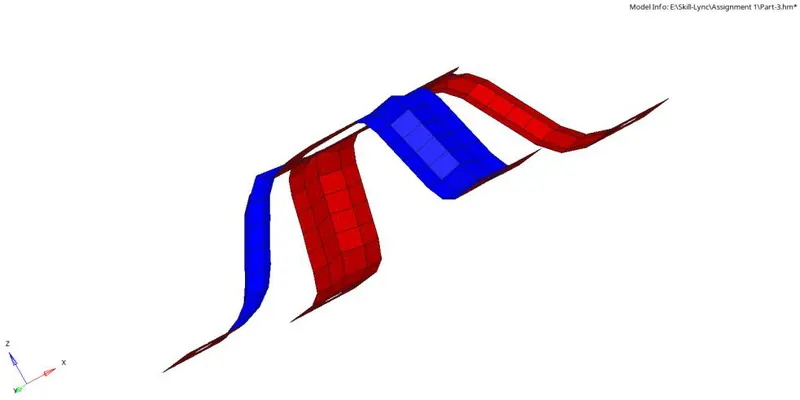
Figure -31 The colourised element normals
Then the mesh is assigned a thickness of 2mm to obtain the detailed representation as shown in the figure below.
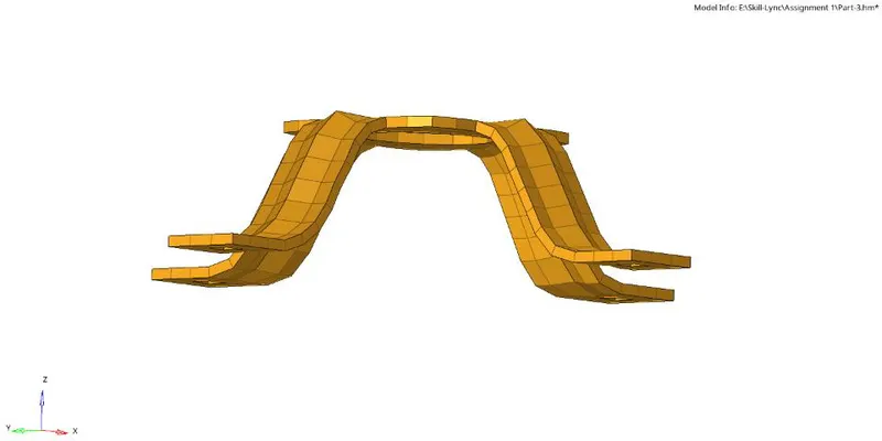
Figure -32 The detailed representation