Assignment 2-RADIOSS Engine File Editing & 3D Meshing Challenge
#ASSIGNMENT 2
Aim: Performing the Radioss Engine and starter file manipulation and also meshing the given components with Tetra and Hexa-meshing
Objective:
Various calculations and steps need to done in order to achieve the desired Outcome
- Check the material property of the rail component and calculate the speed of sound in steel rail
- The length of the rail is about 1000 mm, calculate the time for a shock wave to travel from one end of the rail to the other
- Time for sound to travel along the length of the rail
- Edit the engine file so that stress wave can be monitored, moving from one end of the rail to the other during impact, this will require a termination time equal to the time it takes for the sound to travel the length of the rail.
- Set the frequency of animation output to time that will give 20 animation steps (ANIM/DT)
- Change/Print- 10
- Performing the tetra and hexa meshing to the given component with Target tet size = 5mm, hex size = 10 mm tet-collapse = 0.15
Introduction:
RADIOSS STARTER FILE: The starter file contains the model definition, definition like unit, material, property nodal information and boundary condition, interfaces, load collector, geometrical information etc. are include in starter file.
A radioss starter input file name is runname_0000.rad and the output file or listing file name is runname_0000.out also it contains restart file named as runname_0000.rst
RADIOSS Engine File: The Engine file describe the run control, it controls the engine speed and contain the information about software version the run time, time history file and animation file etc
A radioss Engine input file is name as runname_0001.rad and output file or Engine listing file name is runname_0001.out
RADIOSS Starter and Engine file are ASCII files, these files contain characters, numbers and punctuation tabs, we can create and edit an ASCII file using Notepad, it means that it is readable, where as other file like restart file, time history file and animation file type are binary file type we can’t read that.
Radioss Engine File Guidelines
Engine file – runname_0001.rad
The engine file consists of various case control, the engine file produces the various output such as output contours, which are requested and then Time History plots and also Radioss engine is used to restart the run.
Various fundamental entities that are to be defined in any engine file, these 4 basic fundamental entities are to be present in any engine file and can’t be neglected
- Termination time
- Contour output request
- Animation frequency
- Time-History frequency
- Termination Time: Termination time is the event time or the event which has been consider for simulation, in other word it is time as to how long the even take place
- Contour Output request: Here we request all the contour that we need to present as output, various contours that we are purpose as output generally are stresses, strain and displacement etc. these can be requested as output in the engine file
- Animation Frequency: Animation frequency will specify the time interval at which the animation need to be returned during a radioss run.
- Time History frequency: It is the time gap or time interval at which the radios engine writes a time history plots.
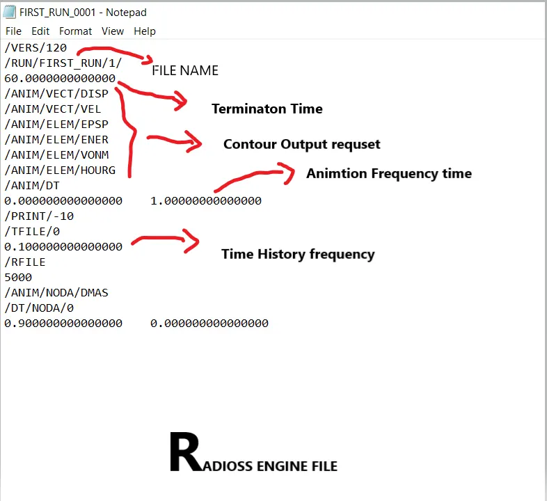
When you see the Engine file first you see the version of the engine file. The first thing and basic fundamental entity that have to be defined in an engine file is Termination Time, the next fundamental entity which we saw is contour plots, and the next fundamental entity is animation frequency.
So, the animation frequency is the frequency at which the animation files are to be returned by the running radioss. The next fundamental entity is time history frequency given by TFILE
The animation file in Radioss for which we requested can be imported into hyper-view by either importing the A001 animation files or either importing .h3d file, by importing this into hyper-view we can check for the various contour.
Time History file which is TFILE in radioss they can be imported in the hypergraph and we can able to see the time history plot in hypergraph
Guidelines need t be followed during the definition of RADIOSS Engine file
Let consider termination time = X
Animation frequency = Y (ANIM/DT)
So, if Y = X/30 if Y > 5e^-3 then we take Animation frequency Y as 5e^-3
The reason to divide it by 30 is to ensure that we got 30 animation files, This is again done in order to make sure that we have smooth transition during animation and there is no staggering effect in the animation. So, taking the value 30 s to ensure that we got a smooth transition in the animation
Time history frequency (Z)
Z = Y/10
Termination time:
For Quasi-static run time depends upon the loading function, let say if loading is done in a period of 0.3s then termination time or event time is directly equal to 0.3 seconds
For Impact situation we have to run the simulation till the Internal energy and kinetic energy should balanced
Note: This is not mandatory o hard and fast rule that you can follow, but from here you got an idea to set various parameters of Radioss Engine file.
Calculation:
- Here we have stater file provided (FIRST_RUN_0000.rad), from that file following parameter were identified
Modulus of Elasticity (E) = 210000Mpa or 210000N/mm^2 (Steel)
Density of steel, Rho () = 0.0078 g/mm^3
Length of the rail = 1000mm (Given)
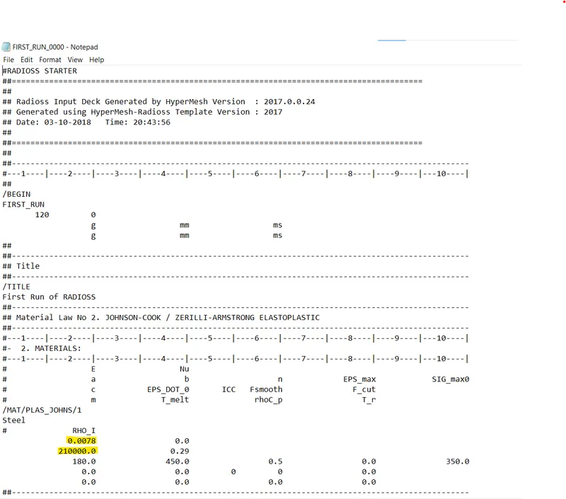
Value of E and Rho for a material in a starter file
- Speed of sound in Steel rail (C):
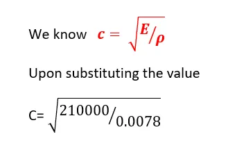
C = 5188.7452 m/s
- Time taken by shock wave to travel length of the rail
Given, Length of the rail is 1000mm or 1m so time taken for shock to travel the length would
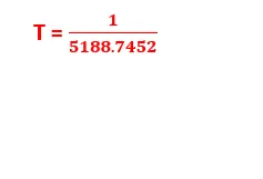
T = 0.00019272 sec or 0.1927ms
- Time for sound to travel length of the rail
Since we know that shockwave or stress wave travel with speed of sound irrespective of medium, therefore time for sound to travel length of the rail would also be 0.1927ms
- Termination time = time for sound to travel length of the rail = 0.1927ms
- Frequency for animation output
Animation steps given as 20 so = Termination time / animation types
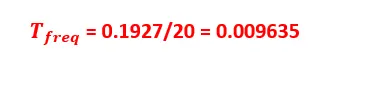
Also, time history frequency = Animation frequency / 10
Z = 0.009635/10 = 0.0009635
- Now all the values created above have to be replaced in Engine file (FIRST_RUN_0001.rad) with initial value, Basically Engine file is a ASCII file, it means we can easily edit it on the notepad, here we are edit the Termination time , animation frequency or Time history frequency value in the file.
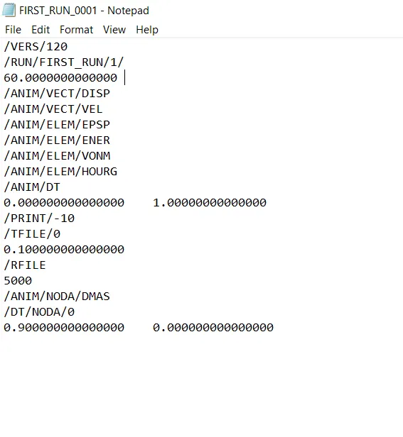
Radioss Engine file with Initial values
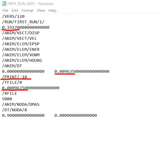
Edited Radioss Engine File
# When to use 3D Elements
We use 3D elements when all of the dimension are comparable ( x-y-z)
Element shape: Tetra, Penta, hex, pyramid
Additional data from the user: nothing
Element type: Solid
DOF for solid elements:
Solid elements only have 3 translation DOF (Degree of freedom), no rotational DOF
Tetra-Meshing Technique:
There are two method of tetra meshing
- Automatic Mesh: This approach is limited to simple geometries and pre-requisite is for error free CAD model. User has to just select the volume and software automatically carried out meshing as per specified element length, quality criteria.
Advantages: Very quick, no meshing effort
Disadvantages: Result in very high number of nodes and elements, There, is no control on mesh flow lines and specific meh pattern requirement (like bolted, welded joint or contact surface simulation)
- 2D tia to 3D tetra Most commonly used method. Quad or tria meshing is carried out on all the outer surface of the geometry, quads split into trias and then converted into tetras
Common algorithms for Tria to Tetra conversion
- Advancing Front: Very powerful and most commonly used algorithm
- Delaunay Algorithm
- Tria-Quad mesh
All Algorithms provide following two option for Tria to Tetra conversion
Floating trias: Not recommended, original tria mesh generated by user on outer surfaces might not match with software produce tetra. Selection of this algorithm gives freedom to software to change the triangular mesh pattern
Fixed trias: Recommended, Original tria mesh and generated tetra mesh pattern matches
Quality checks for Tetra meshing:
Ideal shape for tetrahedron element is equilateral tetrahedron (all equilateral triangle faces)
Various quality parameters check how far a given element deviate from the ideal shape, but mainly we check only for the Tet collapse value
Tetra collapse: defined as the distance of node from opposite face divided by the area of the face multiply by 1.24, This is the most important quality parameter for tetra mesh
Ideal value = 1.0 (Acceptable>0.1)
Other quality checks are Volumetric skew, stretch, Distortion, Jacobian
Other checks for Tetra Meshing:
- Quality check for 2D tria elements: Before converting tria into tetra all the quality checks should be required for checking the quality of tria elements
- Free edges: Conversion from tria to tetra is possible only when there is no free edges, No free edge indicates mesh is forming enclosed volume.
- T-Connection: Meshed model should not contain any T-connection. T-connection is internal (Volume) loop formation in the outer enclosed volume
- Consistent Shell normal: Before converting tria into tetra, shell normal should be corrected.
- Geometry deviation: After completion of meshing, geometry as well as meshed should be view together, Mesh should not deviate from the geometry, sometime nodes get translated too far away from the geometry and not acceptable
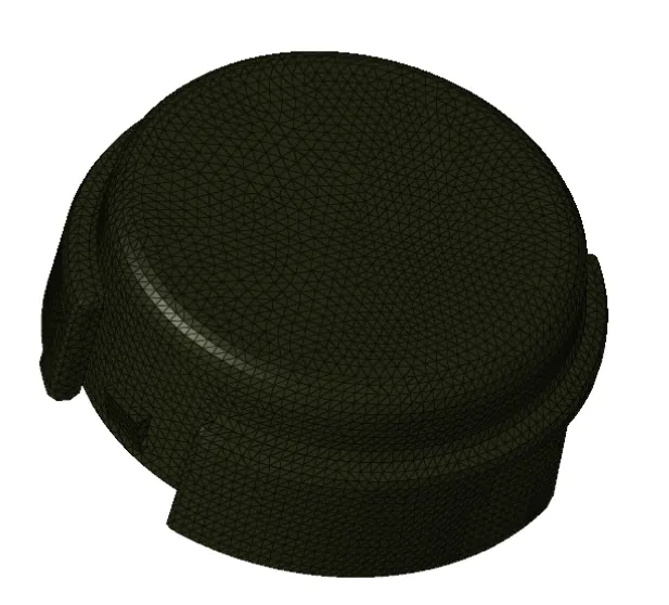
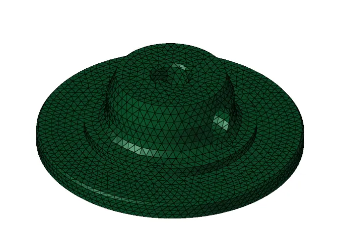
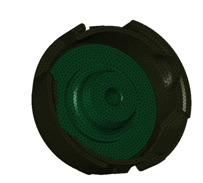
Tetra-Mesh generation of Housing Model:
Tetra-Mesh Generation method is 2D to 3D Conversion
Elements sizes: Min- 2 Units, Target- 5 Units, Max- 7 Units
Tet collapse: 0.15
- Here firstly we have to create the 2D tria elements then we have to convert it into 3D tetra Mesh, but before creating tria element we have to look for geometry and clean the geometry first.
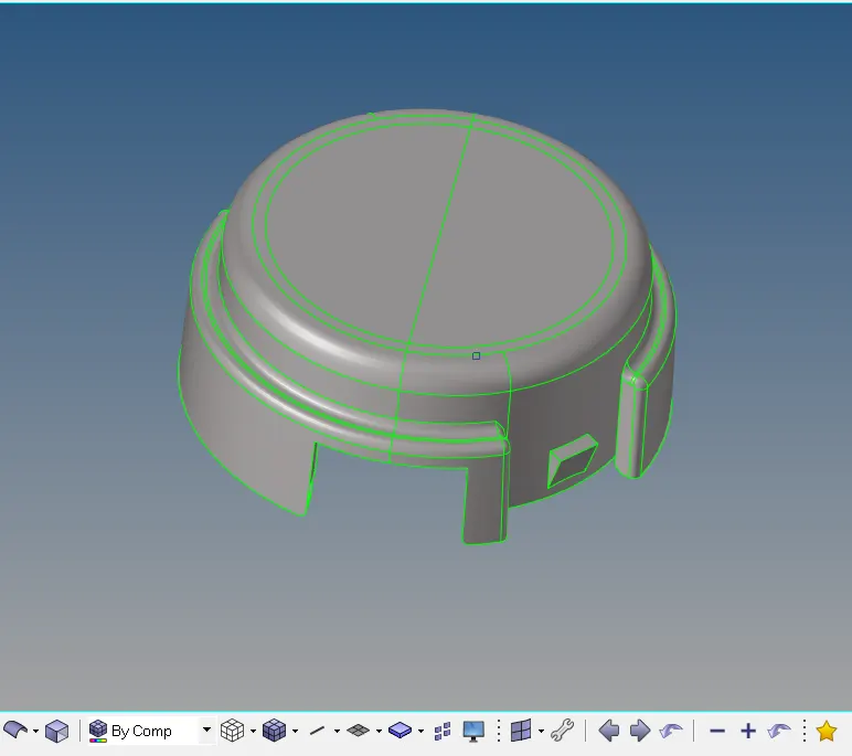
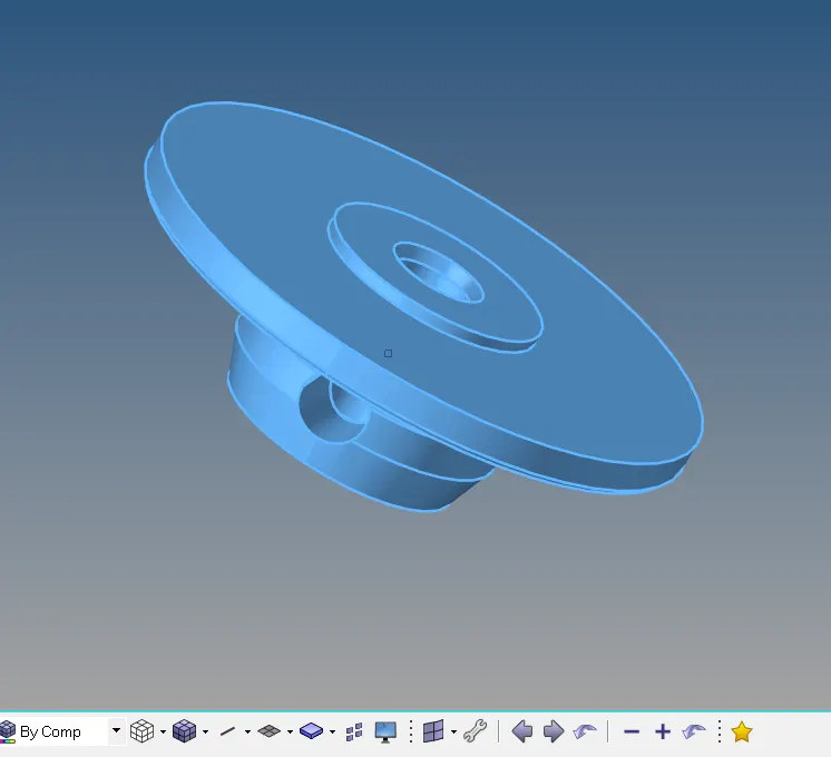
- Here we have solid part, so we have to delete the solid part and keep remaining the surface for meshing, Solid is deleted from geometry because it is easy to mesh on surface rather than solid, and also mesh visualization is easy for geometry with surfaces.
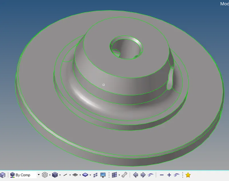
- Now next step is to check for the geometrical errors in the geometry, we have to clean the geometry either manually or by using auto-clean-up option in geometric panel.
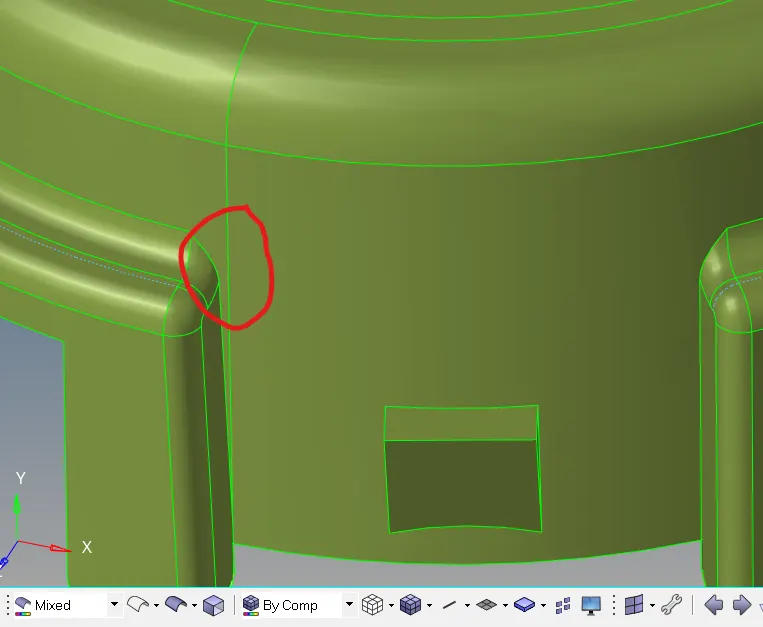
Suppress this line by Toggle option in quick edit panel (F11 shortcut)
After Geometry clean-up we can start the mesh with tria elements and also, we have to check for the element quality.
Elements sizes: Min- 3 Units, Target- 5 Units, Max- 7 Units
- But before creating a mesh we have to set the quality parameter. To, set the quality parameter go to Tool > Check elements > setting > Quality criteria editor.
- Now we can mesh the component with Tria element having the element size of 5 units
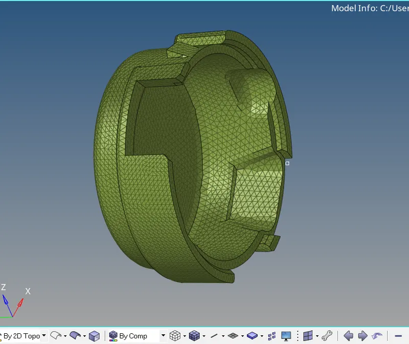
- Now after mesh is complete, we have to check for the quality criteria, if any element will fail then we have to optimize the element by using element optimize option. For quality criteria go to 2D panel > quality index either press F10 for quality check.
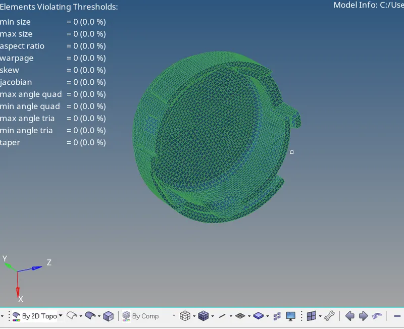
Meshed component passing all the quality parameters
- Now we have to mesh the inner part of the housing
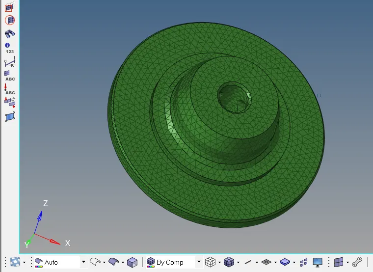
- Now after meshing is done, we have to convert the tria shell elements into 3D Tetra elements, Go to 3D panel > Tetra mesh, Tetra-mesh dialogue box is open

- Now firstly we have to set the tetra-mesh parameter and after that go for Fixed tria to tetra mesh option so that software should not automatically changes the original mesh. Select the elements and hit in mesh option for 3D Tetra mesh
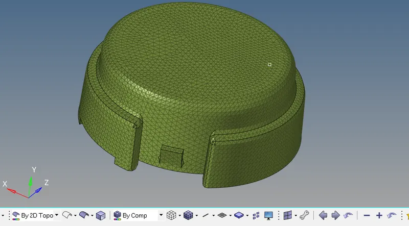
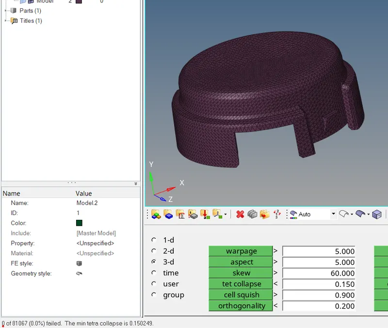
- After 3D meshing is complete, now we have to check for the quality of parameter, we only check the value of Tet collapse
For Quality check Go to Tool > check elements > 3D > Tet collapse (Shortcut of 3D quality panel F10)
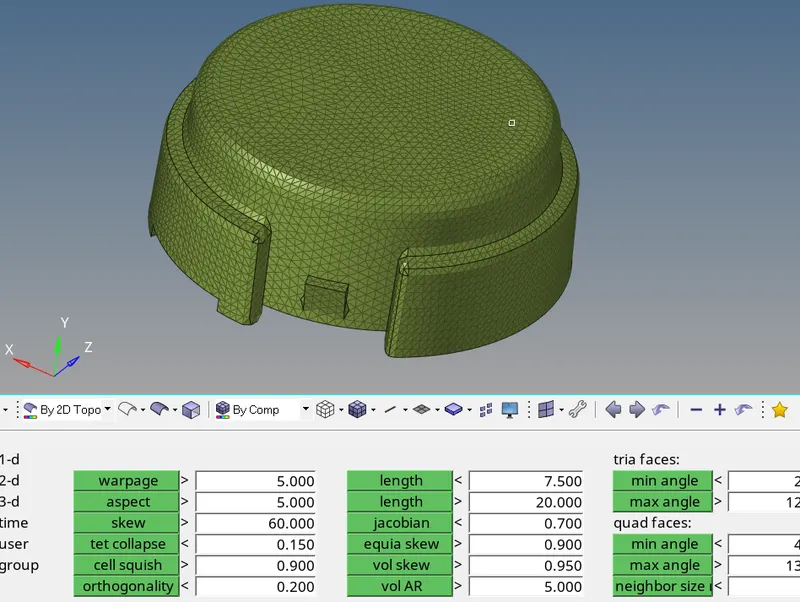
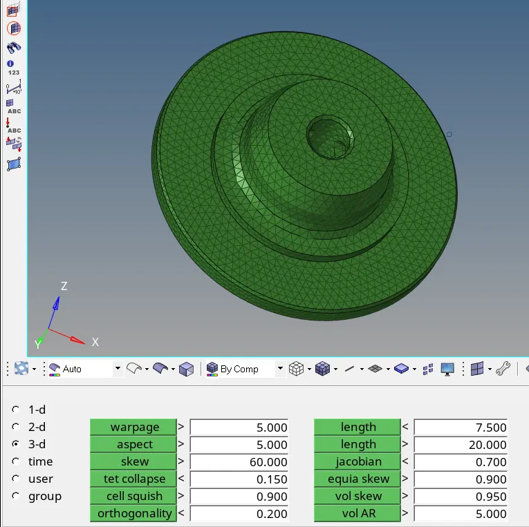
Check out for the Tet collapse parameter
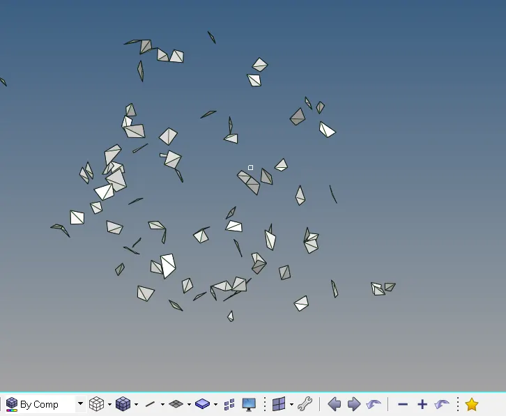
Element failed by Tet collapse
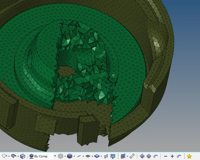
- Software provides the auto algorithms / localized re-mesh facility for improving the mesh quality, These, program improve most of the element but some might remain as it is. For such element quality improvement is carried out via manual shifting / translation of nodes.
Hexa Meshing
Model:
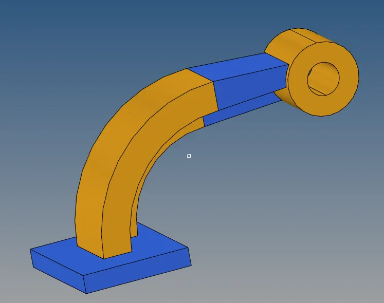
- Here we mesh the component one by one
- Firstly, we have to check the component, whether there is any error is present in geometry or not, if error is present then we have to remove the error and clean the geometry
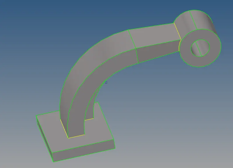
Cleaned geometry
- Firstly, we mesh the Base component with quad mesh and then we convert it into Brick mesh (Solid mesh)
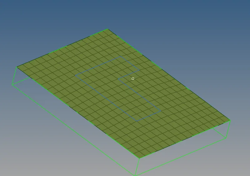
2D meshing of the Base surface
- Now to convert it into solid mesh or brick mesh, go to 3D panel in hyper-mesh, here we choose the element offset option to convert the 2D mesh into the Hexa-mesh
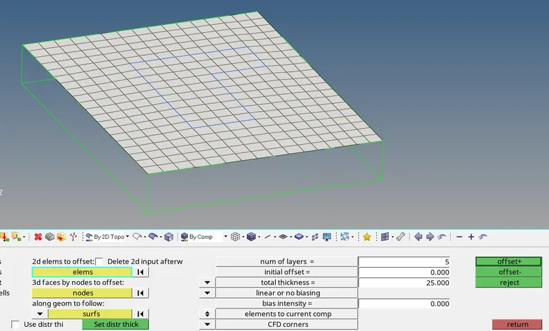
- Select the element to offset and also, we have to select the faces along the geometry so that it can act as guide during meshing, also we need to set number of layers and define the thickness equal to the thickness of the Base surface, after that select offset button to create the Hexa-mesh.
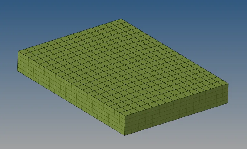
Hexa-mesh is generated
- Now we have to mesh the Arm part for that we are using the spin option in 3D panel to create the mesh, for that we require an axis across which we have to spin and also a base node which is the arc center of the Arm
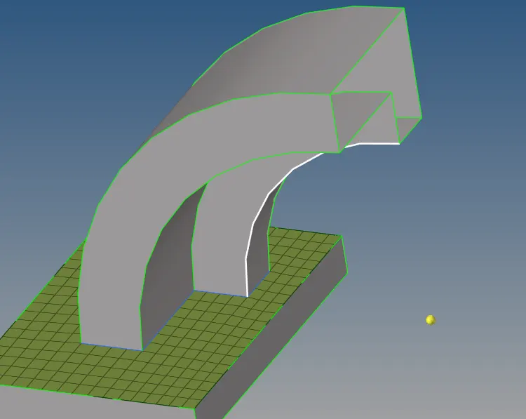
Creating a temporary node to define it as a base node
- After creating the temporary node now we have to select the element that we have to spin
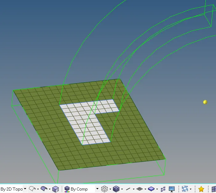
Selecting the element for spin
- After selecting the element select the base node and also define the on spin to 24 elements, it will create the 24 elements on the side along with the spin
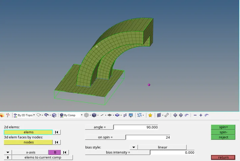
Arm is meshed properly
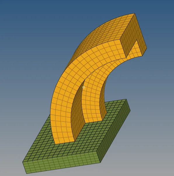
Base and arm meshed model
- After that we have small tapered section, for that we are using linear solid option to create the hexa-mesh, but to use that option we require face or 2D elements, so firstly we need to create the 2D elements on that face, for that we using face option to create the face elements
- To create face elements, go to the Tool > Faces, Select the mesh and click on find face to create the face elements
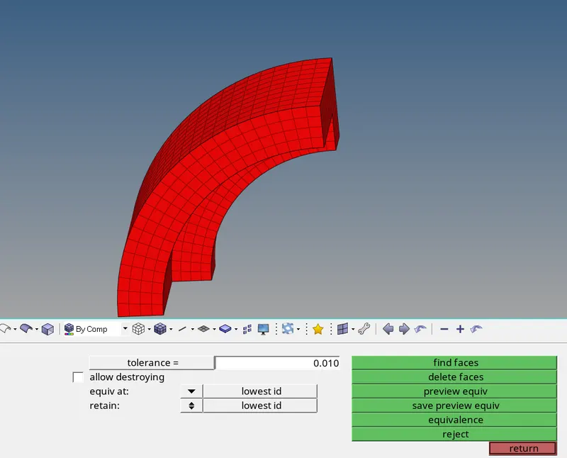
Face element has been generated
- After that we have to mesh the other side of the section with same number of elements, for that we have to match the number of elements creating on the edge, any misalignment leads to creation of penta-mesh
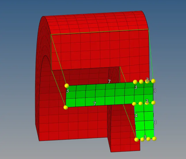
Matching the number of elements
- After that select the both the faces elements, and also define the alignment properly by nodes, select the same number of nodes as alignment on both the faces.
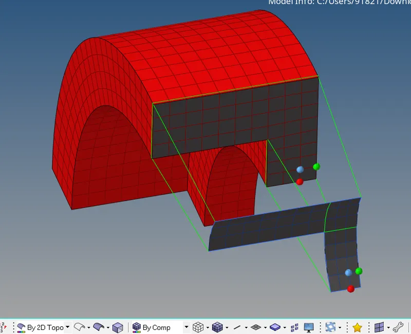
Setting the alignment
- After alignment click on the solid to create the Hexa-mesh

Hexa-mesh is generated for tapered section
- Now we have left only the boss component, for that we are using solid map option to create the mesh, for that firstly we need to mesh the upper part of the cylinder, make sure that number of elements is matching with the Arm elements.
- After meshing the upper portion of the cylinder, now we have to select that mesh and also, we need to select the Destination surface, and for guidance we choose the mixed option, we select both the lines and nodes for proper element connectivity.
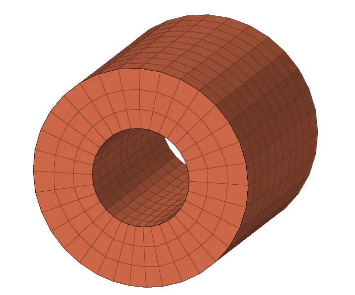
Meshed model of Boss
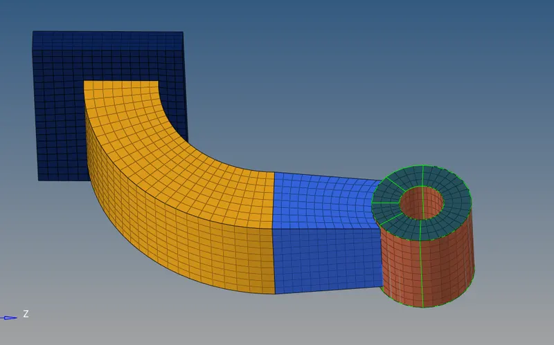
Completely Hexa-meshed model
- After completely meshed the model make sure to delete the faces or 2D shell elements, for that go to delete option, here the selection of 2D element become tricky, so that we choose element by BY-configuration option, define the quad 4 element, it automatically selecting all the shell or 2D elements, now we can delete them.
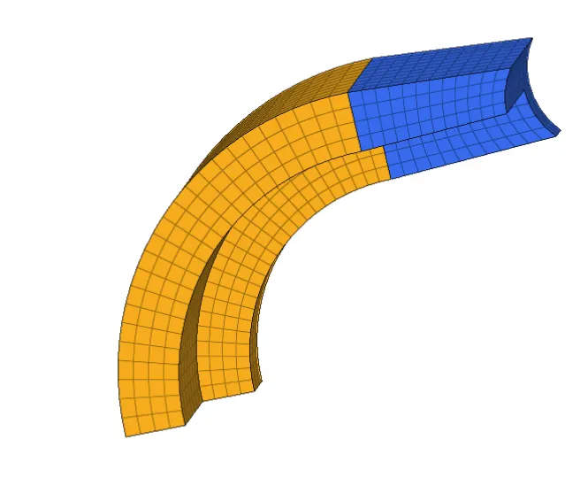
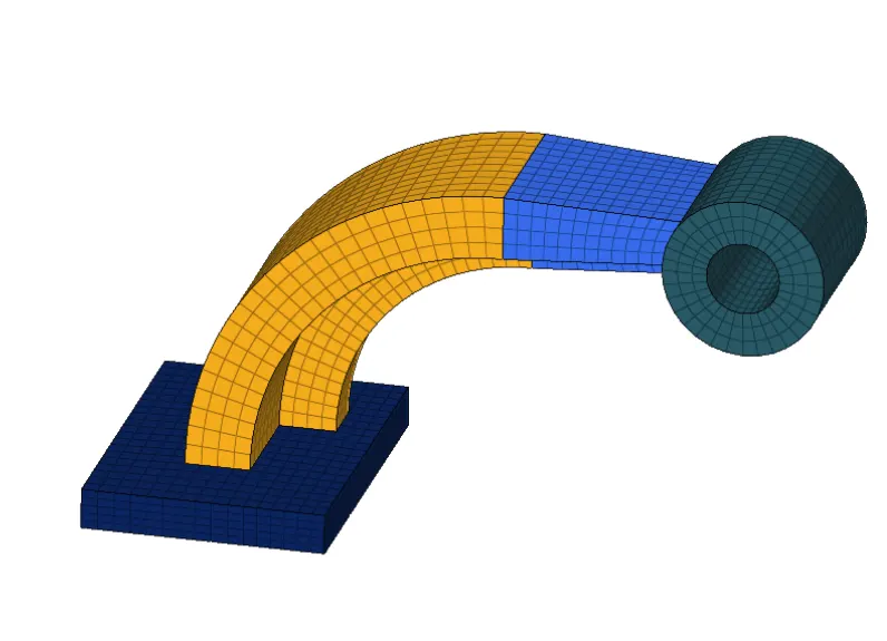
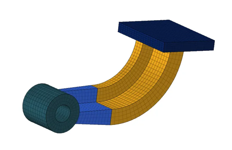
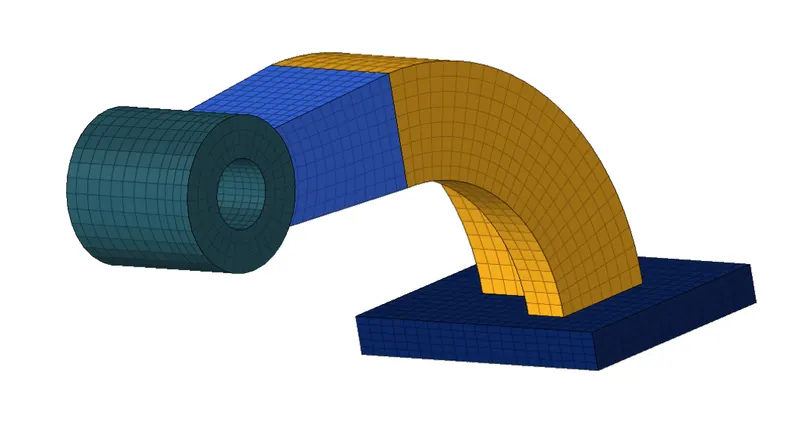
Final meshed model
Learning outcomes:
- Able to understand the Stater files and Engine files of the radioss
- Able to understand about how to edit the engine file
- Able to understand about the time step and basic fundamental entities in Engine file like Termination time, contour output request, Animation frequency, Time-History frequency
- Able to understand about the meshing technique and rules behind the Tetra meshing and Hexa-meshing