Assignment 2-RADIOSS Engine File Editing & 3D Meshing Challenge
Objective:
1. Check the material properties of the rail component and calculate the speed of sound in steel rail=_______
2. The length of the rail is about 1000 mm.calculate the time takes for a shock wave to travel from one end of the rail to the other.
3.Time for sound to travel length of rail=______
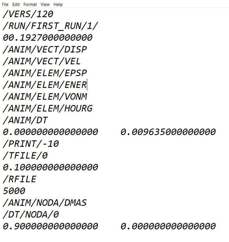
4.Edit the engine file so that the stress wave can be monitored, moving from one end of the rail to the other during impact -this will require a termination time equal to the time it takes for the sound to travel the length of the rail(set on/RUN card)
5.Set the frequency of animation output to a time that will give 20 animation steps(/ANIM/DT)
6.Change /print -10.
7.3d meshing tetra mesh and hex mesh
- Repeat class examples and, maintain the quality.
- Target tet size=5mm,hex size=10mm,tet collapse=0.15.
Procedure:
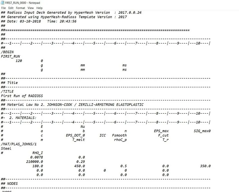
- For the radioss starter out file FIRST_RUN_0000.rad .the initial information above the material properties to be determined.
- Here the material used is steel and the unit system is g-mm-ms.
- The material properties in the above the unit system are:
- Density(Rho)=0.0078 g/mm^3
- Young's modulus(E)=210*10^3 g/(mm.ms^2)
- poisson's ratio=0.29
-
- speed of sound can be calculated using the relation
- on substitution of the above values we can obtain c as 5188.74 mm/ms.
- Criticsl time step
- using the length of 1000mm, the =0.1927ms.
- The time interval at which plot should be written for 20 steps=0.1927/20=0.009636 ms.
Radioss Engine Out file editing
The radios file FIRST_RUN_0001.rad and contains the information above the critical time steps and the interval at which output plot were written.
3D Meshing for the housing:
- Importing the given model into the GUI.
- Then we should switch on and off the two parts present in the model so that we can work seperately on the components.
- For the volume tetra mesh they were three ways to do the meshing by 2D tria to 3D Tetra meshing and quick volumetric mesh and volume tetra herdal mesh.
-
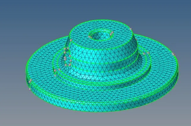
- So that for 2D tria mesh we should go to the 2D auto mesh and select the component and do auto meshing with target element size as 5.
-
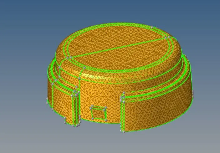
- After 2D meshing we should go to 3D meshing and select the volume terta mesh and meshing the component and we should check the parameter and tet collopase for the parts.
-
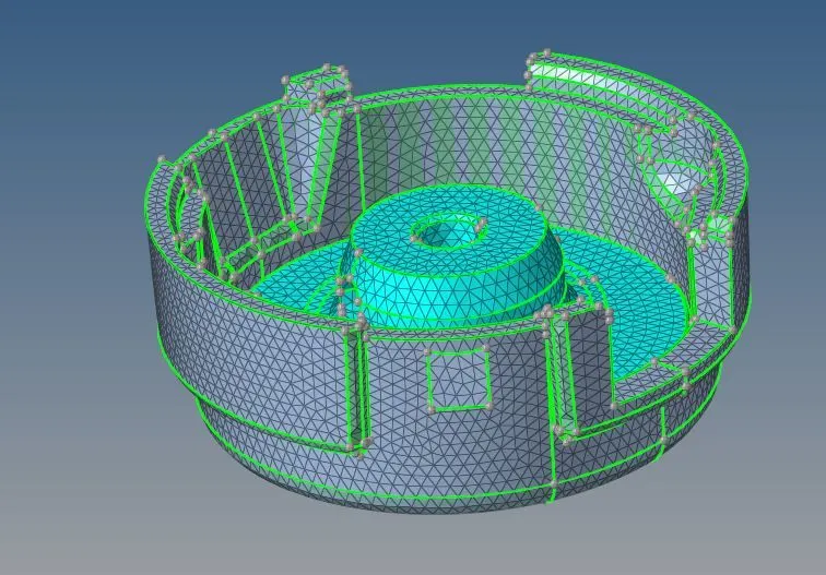
- In this way we can do by quick terta mesh by utlity>Hypermesh> Tetra meshing and giving the target element sixe and selecting the Tria can be formed the 3D mesh.
-
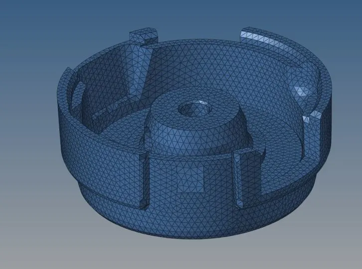
-
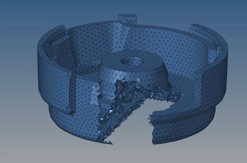
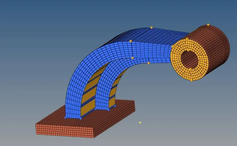
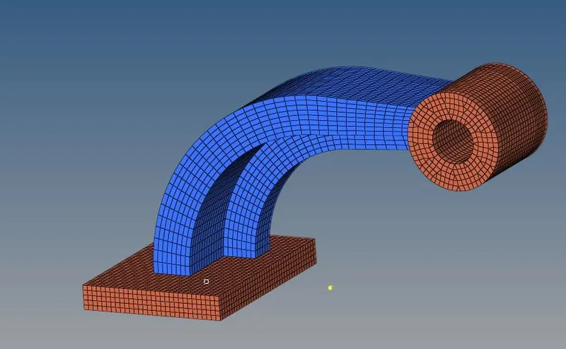
Hexa Mwshing of an Arm Bracket:
- To start with it we have to isloate it form it from rest of the component ,which can be done by using mask command available in tootl sub panelonce it isbeen isloated as shown above we can move towardsfurther conditons.
-
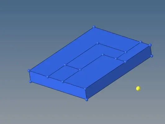
- The component that the base is not a closed volume right now so we have to close the surface using ruled frpm the 2d panel.
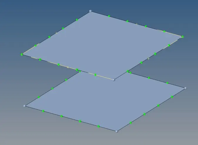
- In the rulws command we have to select 2 sets of the lines between which we have to create a surfaceand form the middle drop down selection we have to select surface only which allow suitable area to be created.
- After surafce has been done meshing has to be apply on the surface for which we have used automesh command avialable in 2D panel.
- If the trias available in mesh we have to remove them by using Drag optionaviliable in 2d mesh pannel.
-
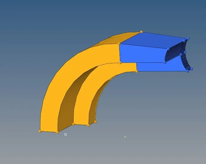
- Once the meshing has been done we have to create element layers.
- For which we have to select element which we have created earlier for along the geomentryselect surface no of layers=5 and thickness =25
- Then click on offset once the base will appear as complete mesh.
-
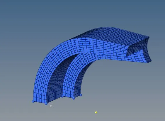
- Moving forward we have to mesh the curve portion for which we have to hide hexa element in base and only keeping surface mesh element.
-
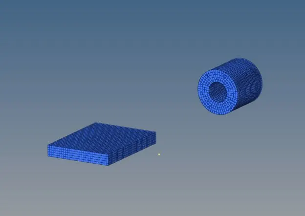
- And use spin command in 3d to extract this mesh in this command we need to select axis passing through the centre of curvatute and give the angle upto the extract spin fianally.
- After curve portion is been meshed next portionof this bracket is straight tapperwhich is meshed with linear solid 3d mesh.
- Select the component and click on faces.
- Mesh the opposite side of the portion number by rows and column.
- Once after clicking the meshing enter the solid drag and destination of the surface along the geomentry.
-
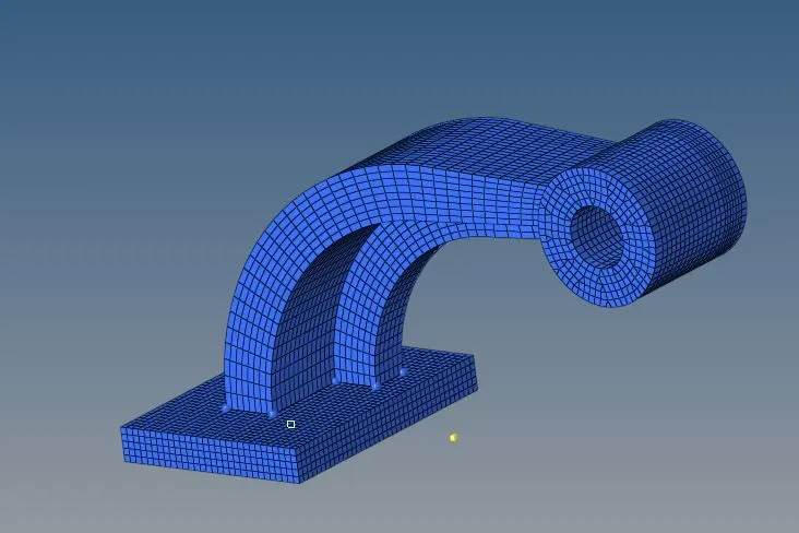
-
-
Procedure for the ID element :
- Create a new surface by using the ruled option.
-
- we should mesh the component and check the flow.
-
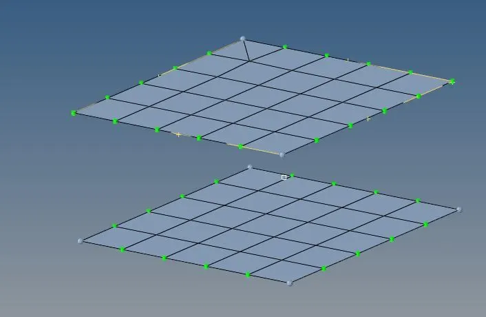
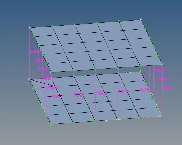
- And we should provide the connections to the given model.
-
CONCLUSION:
- Hence the volume tetra mesh ,Hexa mesh and Connections were been given to the model.