Assignment 2-RADIOSS Engine File Editing & 3D Meshing Challenge
Aim: To study about the starter file and engine file in RADIOSS by changing the parameters for the given file And also perform a 3D meshing on the given components of which one will have tetra mesh and the other one will have hex mesh.
Objective
- Check the material properties of the rail cormponent and calcuiate the speed of sound in steel raile
- The length of the rail is about 1000 mm. Calculate the time takes for a shock wave to travel from one end of the rail to the other.
- Time for sound to travel length of rail=______
- Edit the engine file so that the stress wave can be monitored, moving from one end of the rail to the other during impact - this will require a terrnination time equal to the time it takes for the sound to travel the length of the rail (set on/RUN card)
- Set the frequency of animation output to a time that will give 20 animation steps(/ANIM/DT)
- Change /print -10.
- 3D meshing - tetra mesh and hex mesh.
1 Target Tet Size 5 mm. Tet collapse- 0.15. Hex Size- 10 mm
Solution
- Check the material properties of the rail component and caiculate the speed of sound in steel rail
- So to check the material properties of the material of the rail component. We have to import the component in the hypermesh
- We have the "rad" file. So for that, the profile should be RADIOSS
. Now we go to the import option in .There we are going to select a 0000.rad file and imported.
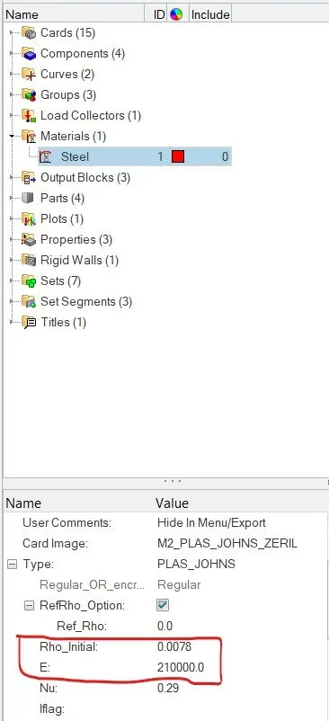
- Now we are going to material property and check the value we can see the density and Young's modulus of elasticity and material property in module browse window
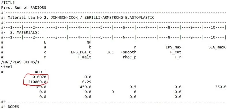
We can also " first_run_0000.rad" starter file in notepad and find a material property as highlighted in the image below
Speed of sound in the material (c)=c=√(E/(e/ ρ )
where E- Young's moduius pa density 210000 So speed of sound (c) = 5188.745 m/s 0.0078
- where E- Young's moduius pa density 210000
- So speed of sound (c) = √(210000/ 0.0078 ) =5188.745 m/s
- The length of the rail is about 1000 mm calculate the time takes for a shock wave to travel from one end of the rail to the other.
- Shock wave traveis at the speed of sound. So
- shock wave speed speed of sound 5188.745 m/s
- time (t) = Distance( D) /Speed of shock wavo
- time takes for a shock wave to travei from one end of the rail to the other 1000/5188.745=0.1927ms
3.Time for sound to travel iength of rail- 0.1927 ms
- Edit the engine file so that the stress wave can be monitored, moving from one end of the rail to the other during an impact -this will require a termination time equal to the time it takes for the sound to travel the length of the rail(set on/RUN card)
- We have to give the end time to be 0.1927 ms. There are two methods to do it.
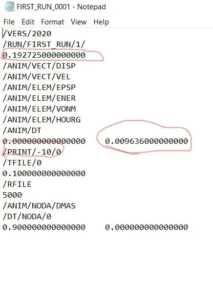
(i). First is just open the "0001.rad" engine file in Notepad and edit the end time value in the file.
Figure below shows engine file before editing the values
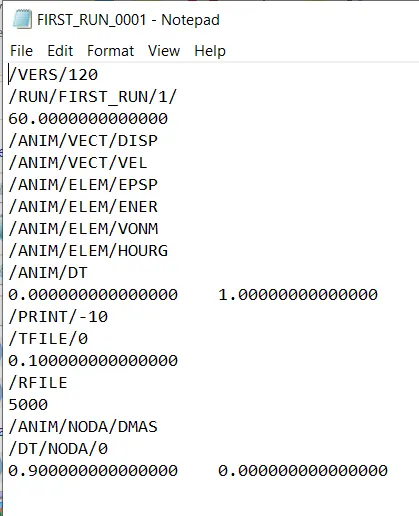
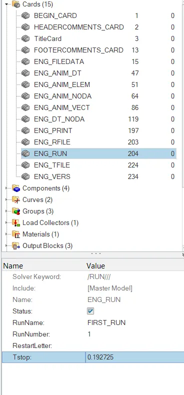
(ii). In the second method, we change the value in the hypermesh itself. There we go to the ENG RUN Card. There we change the Tstop value. There we have to give the value to be 0.1927 and after that, we have to run the file. So it will change the values in the 0001.rad file itself.
- Set the frequency of animation output to a time that will give 20 animation steps(/ANIM/DT)
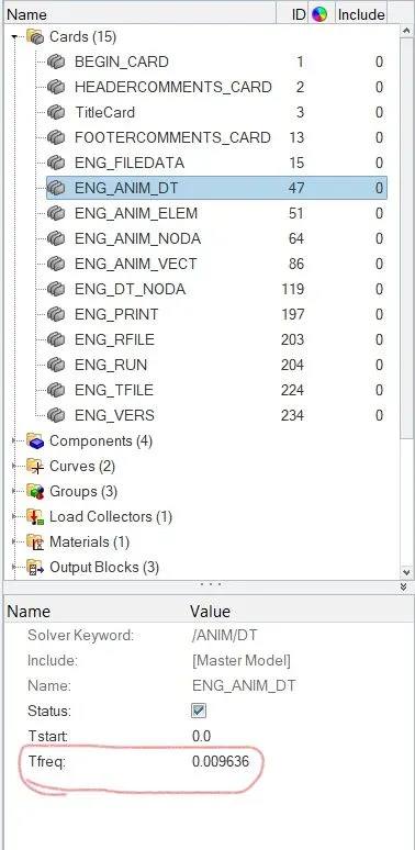
- time= frequency/ no. of revolution 0.1927/20 =0.009636
- So to change this value. We have two methods 20 ). First is just open the 0001.rad file and edit the end time value in the file
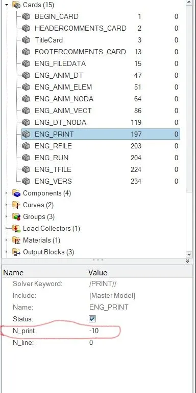
Engine file after editing.
(ii). In the second method, we change the value in the hypermesh itself, There we go to the ENG ANIM DT card. There we change the Tfreq value. There we have to give the value to be 0.009636 and after that, we have to run the file. So it will change the values in the 0001.rad file itself.
-
Object: - Creating the 3D Tetra mesh for these components Housing and Chassis according to the parameters. In this challenge, we are following the below parameters.
Elements sizes. Min - 3mm, Target - 5mm
Tett collapse: 0.15
Procedure:
- Impor the geometry
- Deleting the solid components
- Move the object by using the translate.
- Cleanup the geometry.
- Creating the 2D mesh with given parameters
- Creating the 3D mesh & maintain the tet collapse.
Tet collapse:
Importing the geometry:
3D mesh quality can check by using the tet collapse. Tet collapse can use to measure the height of the tetra elements. This error when occurs when the tetra elements whose collapse value falls below the value specified, Tetra collapse calculation: At each of the four nodes of the tetra, the distance from the node to the opposite side of the element is divided by the square root of the area of the opposite side. The process starts with the importing the geometry. After importing the geometry we are deleting the solid components for geometry cleanup. The geometry cleanup is carried out by using the quick edit tool and surface edit tool
Import solver disk - import model - downloads file. This tool is used to import the model, import solver disk consists of the five different tools like import solver disk, import model, import geometry, import connectors & import BOM. In this, all the tools import solver disk is suitable for importing all types of models. Generally, we are using the HM file, STEP file & IGHS file
Deleting the solid components
After importing the geometry we are starts working on the geometry. We are deleting the solid components because of the 2D element we can not create on the solid component. By using tool delete tool in that solids using we delete the solid components. The below image shows after deleting the solid model.
Move the object by using the translate. The given model is intersecting one surface to another surface while creating the 3D mesh it creates the difficulty. Therefore we are moving the model by using the tool translate. This tool is used to translate the components at any required directions with reference to the base point.
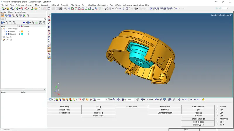
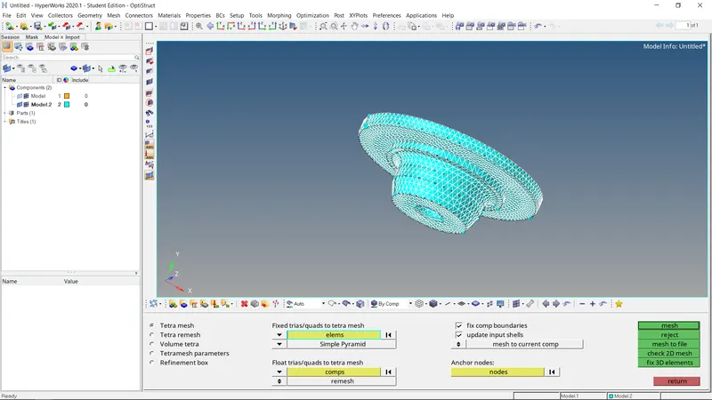
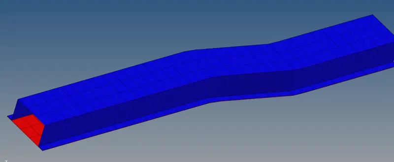
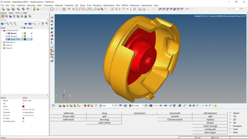
Creating the 3D mesh & maintain the tet collapse. 3D- Tetramesh A 3D mesh is the structural build of a 3D model consisting of polygons, 3D meshes use reference points in X. Y and Z axes to define shapes with height. width and depth. The 3D mesh can be created by two different methods one is using the tetra mesh another is utility option. A region is considered enclosed if it is entirely bounded by a shell mesh (tria and/or quad elements). Other element configurations generated in this panel are hexahedral, wedge, and pyramids. After creating the 3D mesh as shown in the below images.
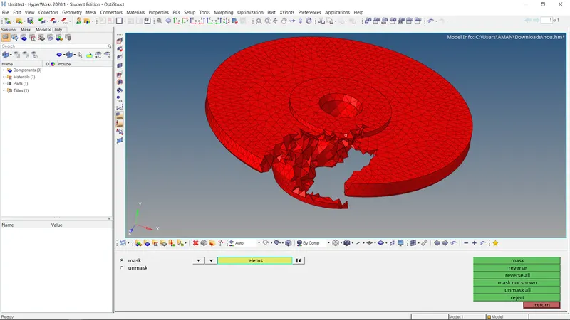
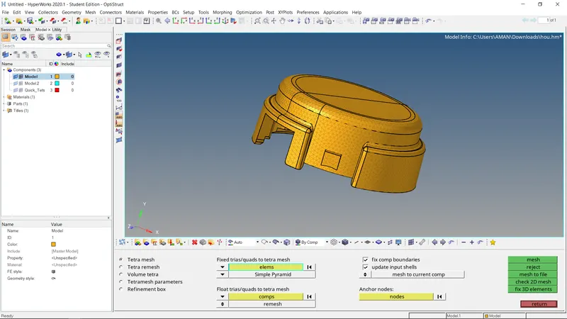
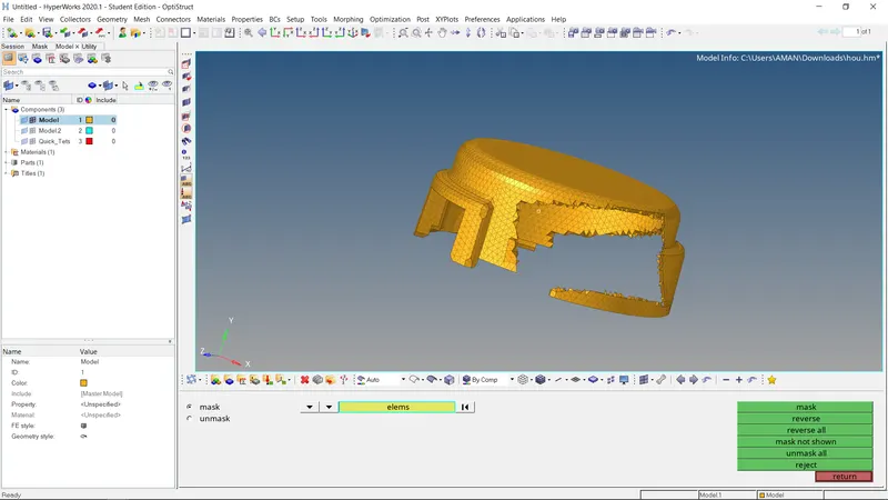
- Go to 30stetramesh Tetramesh parameters>tet collapse: 0.15»Tetra mesh>>elems>displayed>>mesh. 3D tetramesh is created. This is checked by using mask option in the the figure below.
Hexa Meshing
MESHING OF ARM BRACKET USING BRICK ELEMENTS
OBJECTIVE
1 To import the arm bracket model
2 To clear the geometrical error, if any present.
3 To mesh the bracket using brick/hex elements
PROCEDURE
The meshing of any component using Hexa elements is complicated as compamd to the mesh using tetra elements. Generally. tetra mesh is widely prefered when the strem generating on the component are not the part of concem and vice versa in this assignment the arm bracket has to be meshed using only brick elements. To do that, different method had to follow for different sections of the am bracket. Firstly, the arm bracket model was mported into the software
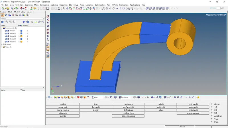
Meshing on one face of section 1 using 2d elements. Now, using 3D mesh with element thickness of 5 units and 5 layers, as shown in fig. 3. elem offset - solid layers, the 2d shell mesh is converted to 3d Hexa
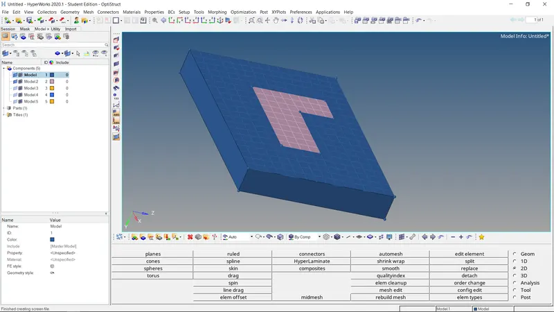
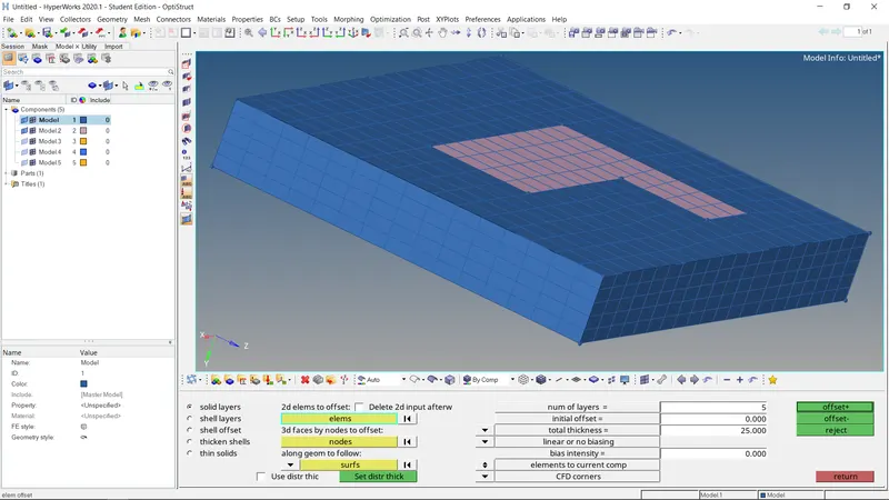
3D Hexa meshing of section 1. After the meshing of section 1, for the meshing of section 2. the different methods had to follow because of its curved shape
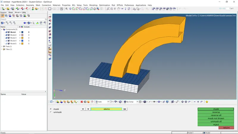
Section 2 with a curved shape To mesh section 2, firstly, a center of the curve is obtained for reference It can be obtained using Georn - nodes - Arc Center, or Geom distance three nodes After taking out the center, using 3D- spin -- spin elems. the shell mesh inscrbed by the curve is selected and it is spin about the center for 90" with 40 layers of elements
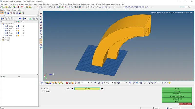
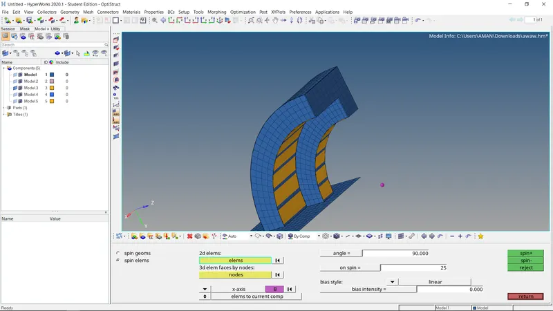
face of 2D
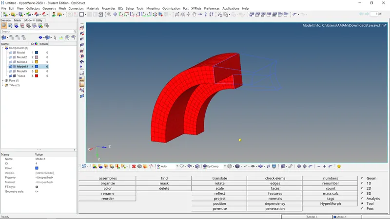
The tapered shape of section 3. To get the shell mesh of section 2, Toolfaces elems is used. It appears exactly lae 3d Hexa mesh of section 2. but when some of its elements are masked, it is hollow from inade Now, to mesh section 3, the rows and colurmns of shell elements available on one side of it the other side has to mesh with the same number of rows and colurmns using shell elerments
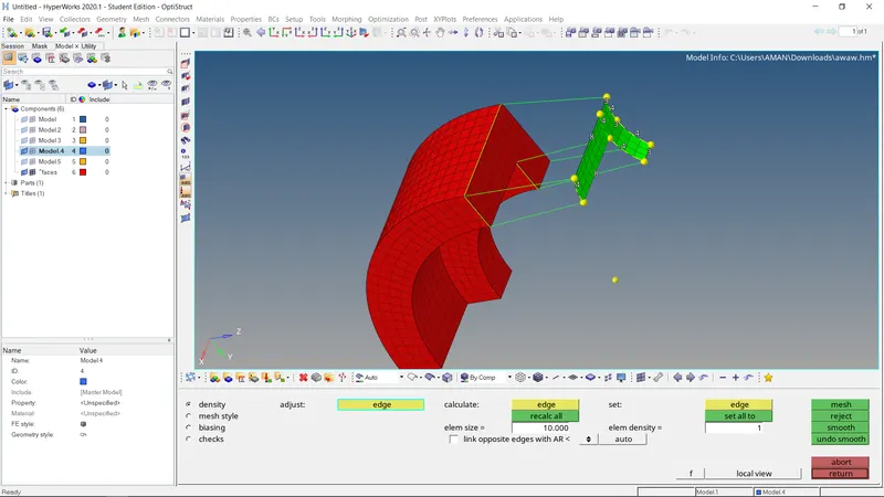
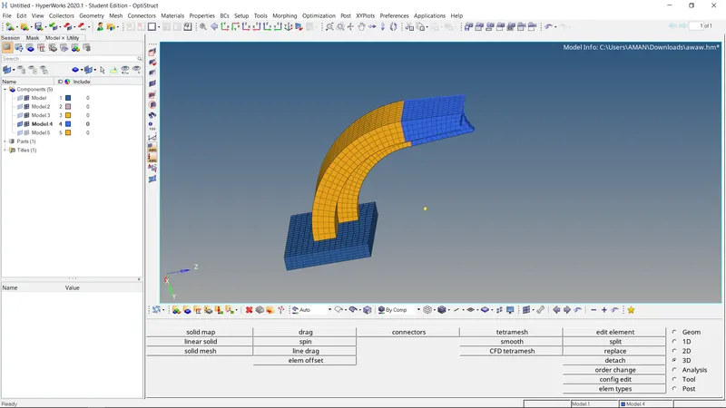
Section 4 or boss section is divided into different smaller sections for Id Hea meshing Using 3D solid map - line drag, providing the shell elements of the boss as sour elements and node path as a reference the boss was meshed
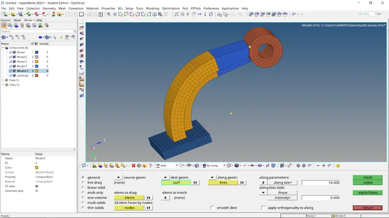
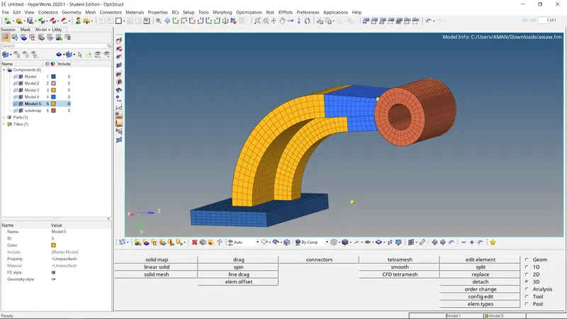
The boss of arm bracket model meshed with 3d Hexa elements This is how all the sections of the arm bracket model mesh and the completely meshed model appear