Assignment 2-RADIOSS Engine File Editing & 3D Meshing Challenge
AIM : Enigne file editing and 3D meshing
OBJECTIVE :
- To calculate parameters from given engine input file.
- Checking the material properties of the rail component and calculating the speed of sound in steel rail
- Calculating the time is taken for a shock wave to travel from one end of rail to another, if the length of rail is 1000mm.
- Calculating time for sound to travel length of rail - To edit engine output file.
- Editing the engine file, so that the stress wave can be monitored, by moving from one end of rail to the other during impact- this will require a termination time equal to time it takes for the sound to travel the length of rail (Setting on RUN card)
- Setting the frequencey of animation output to a time to that will give 20 animation steps (/ANIM/DT) - To connect 1-D different collectors to given geometry
- 3D Mesh of arm bracket.
- Hex size = 10mm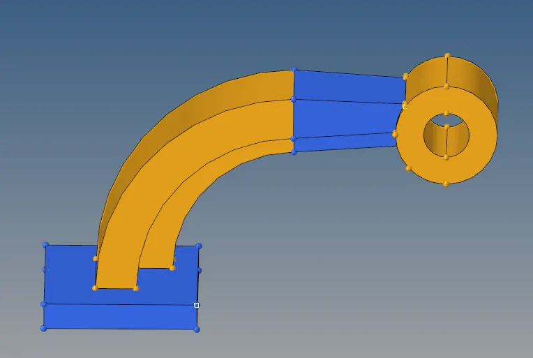
- 3D mesh of Housing components.
- Target tet size = 5mm
- Tet collapse = 0.15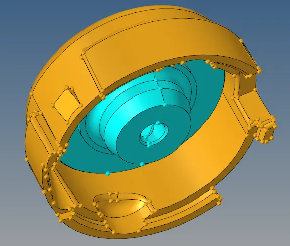
- Procedure for objectives
1. Check the material properties of the rail component and calculate the speed of sound in steel rail=_______
Sol : Given 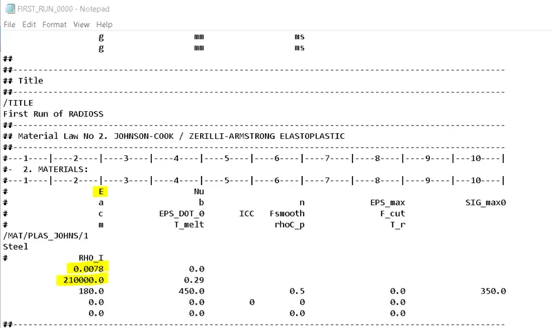 we know that --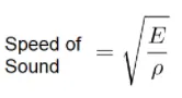
Calculation --
> Speed of sound =  (Modulus E / Density ρ)
- From given data substitute values
= (210000/0.0078)
= (21/78)^½ *100*100 (Converting decimal to simple)
- speed of sound = 5188.745 m/s. -- eq 1
2. The length of the rail is about 1000 mm.calculate the time takes for a shock wave to travel from one end of the rail to the other.
Sol: given Length of rail = 1000 mm
we know that-
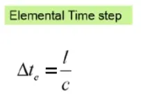
Elemental time step = (Length of element / Speed of sound)
calculation :
- Element Time Step = 1000 mm / 5188.745 m/s (from eq1)
= 1 m / 5188.745 m/s (Converting mm to m )
- Element Time Step = 0.0001927 s -- 0.1927 ms - (eq 2)
3. Time fpr sound to travel length of rail = _____
Sol : Time fpr sound to travel length of rail is same as Shock wave travel in rail. i.e 0.1927 ms. (from eq 2).
4. Edit the engine file so that the stress wave can be monitored, moving from one end of the rail to the other during impact -this will require a termination time equal to the time it takes for the sound to travel the length of the rail(set on/RUN card)
A : given
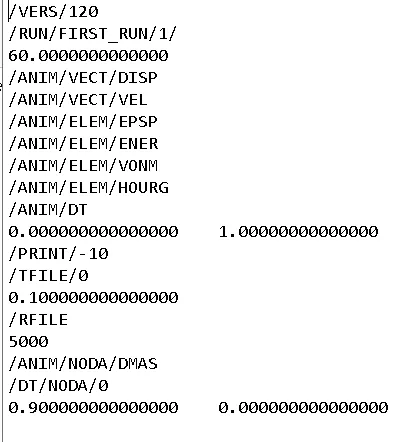
here we have to replcae 60.0000000000000 with 00.1927000000000 (With extact digit).
5. Set the frequency of animation output to a time that will give 20 animation steps(/ANIM/DT)
Sol: No. of animation steps = 20
- wkt T frequency = Time of sound travel / Np. of animation steps
= 0.1927 / 20
T frequency = 0.009635 Hz
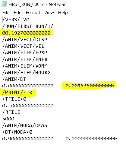
- Repace 1.00000000000000 with 0.0096350000000
6.Change /print -10.
- No change
- Results
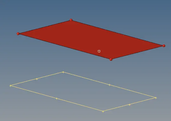
OBJECTIVE 3 : To connect 1-D different collectors to given geometry
STEP 1 : Creating temp nodes at all points
*geom--temp node--select all corners--add
STEP 2 : Obtaing RBE2 rigid element at one of the corner of the geom
*1D--rigids--create--select independent node--select dependent node--elem type RBE2--Create
STEP 3: Obtaining spring elem at second corner
*1D--springs--create--select nodes--HMSPRING elem type.
STEP 4 : Obtaining RBE3 elem at 3rd corner
*1D--RBE3--create--select nodes.
STEP 5 : Obtaining rod elem at 4th corner
*1D--rod--create--select nodes--Crod elem type
Final image : 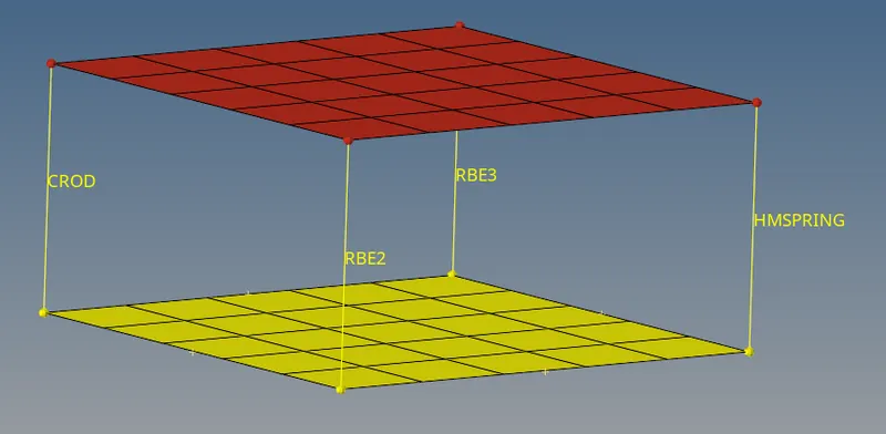
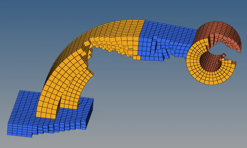
Obejective 4. 3D Mesh of arm bracket.
- Hex size = 10mm
STEP 1. 2D Mesh on the base comp with 10 mm.
*2D--automesh--surface--mesh
STEP 2 : 3D elem offset of 2D elem of base comp
*3D--offset elem--solid layer--select 2D elem--select along surfaces--no. of layers (5)--total thickness (25)--offset. 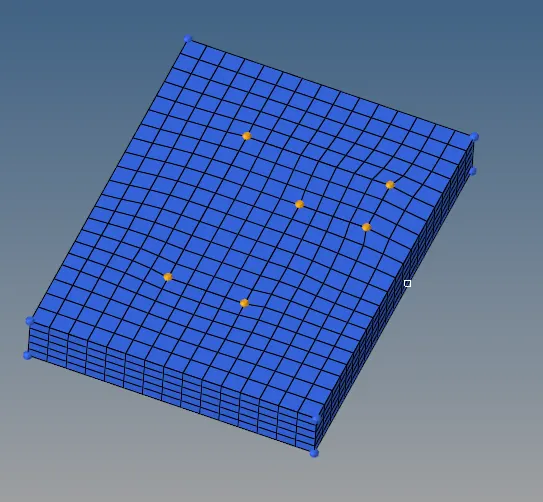
STEP 3 : Mask hex8 elem by congfig, so that only 2D elem will be displayed, it will help us to 3D mesh arm curve comp.
*F5--elem--by config--hex8. 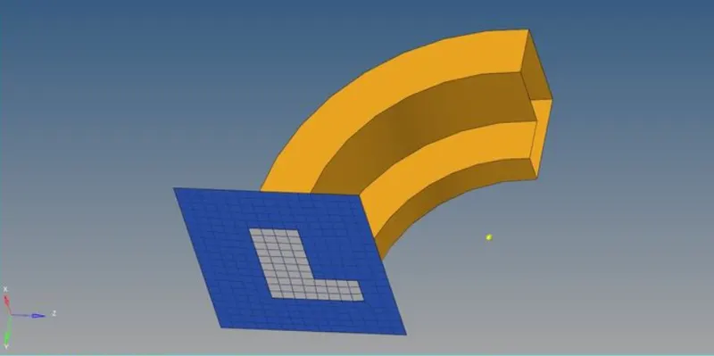
STEP 4 : Create a cantre node of a arm curve comp, it will help us to spin elem.
*F4--3 nodes--select line-- create random 3 nodes--circle center.
STEP 5 : Spin panel can be used to spin 2d elem of base to arm curve comp.
*3D--spin--spin elem-select 2D elem--select (x axis) for rotation--select base node--angle(90 deg)--on spin(25)--spin.
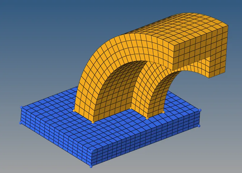
STEP 6 : 2D Mesh on the front side surf of arm straight
note : No. of elem on arm straight should be equal to no. of elem of last face of arm curve.
STEP 7 : Find faces of arm curve
*Tool--faces--select arm curve comp-- find faces
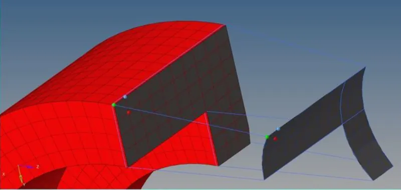
STEP 8 : 3D Linear solid panel can be used to create 3D elem in arm straight as ---
*3D--Linear solid--from elem--select elem of first surf by face--select alignment node--select elem of second surf by face--select alignment node--density (25)--solids.
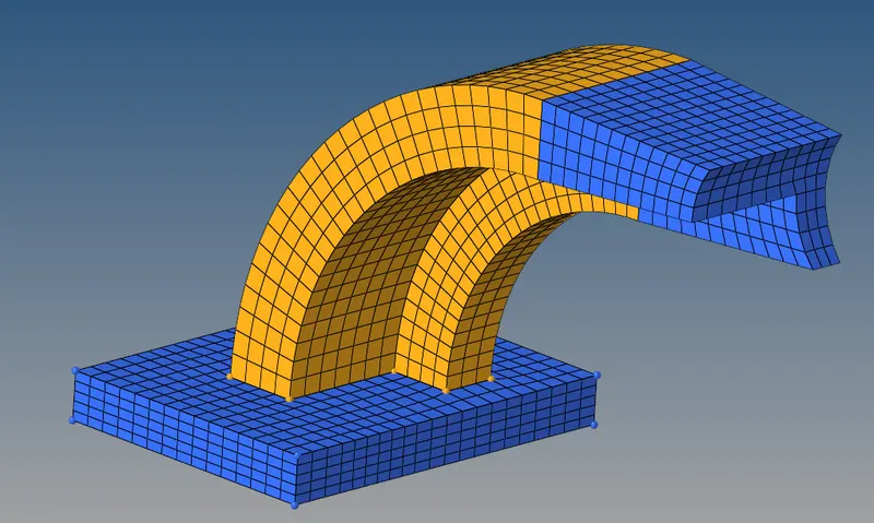
STEP 9: Create 2D mesh on one side of circular upper face of boss comp. Keep equal no. of elem at inner and outer.
- Before meshing for other face check for equal elem while solid map for adj surface.
- Create temp node at both end of circular faces align to adj elem.
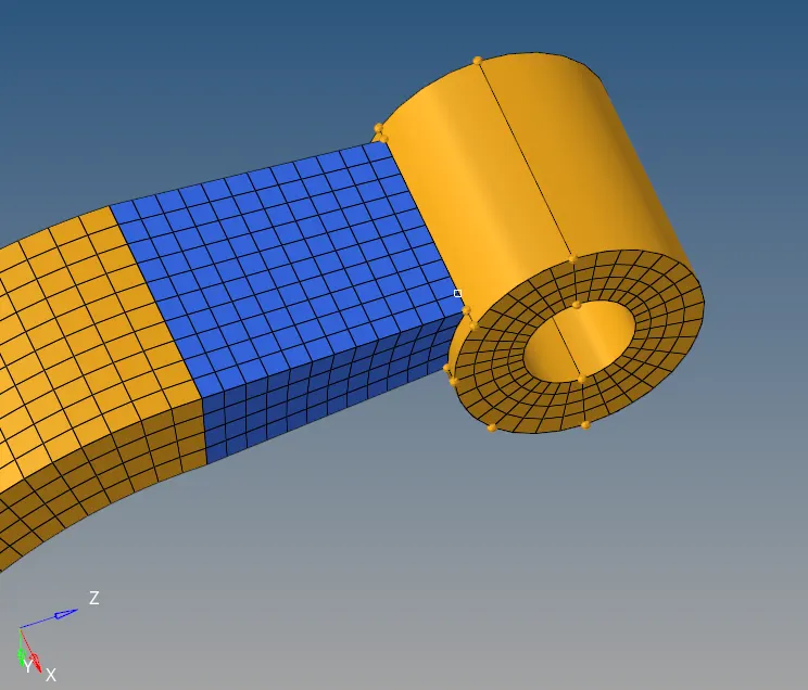
STEP 10 : To create 3D elem in boss comp. we can go for solid map panel.
*3D--solid map--gen source(none)--select elem by face--select dest surf--along geom--mixed--node path--select line--along parameter size (12)--mesh.
- we can see a new collector has created of 3D elem of boss, so we can organise those to boss components.
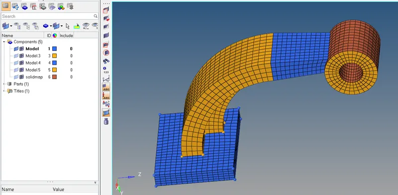
STEP 11: Deleting 2D elem from whole arm bracket comp.
-- Mask 3D elem by config hex8
-- Delete 2d elem
- Final image
Objective 5. 3D Mesh of housing comp with target tet size 5 mm and tet collapse 0.15
STEP 1 : 2D mesh on cover with 5mm tria elem
*2D--automesh--surface(displayed)--5mm elem size--tria type--mesh.
STEP 2 : Now we have to go for 3D tetramesh
*3D--tetramesh--select elem(displayed)--simply pyramid--mesh.
- we have to do the same above steps for hub.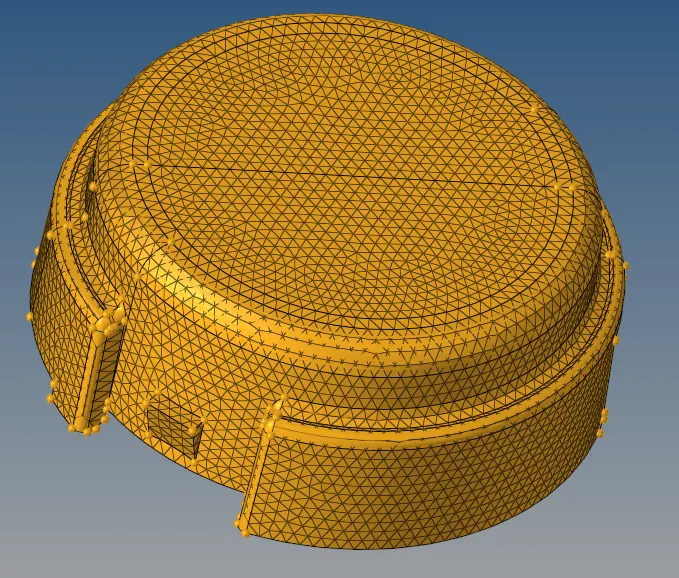
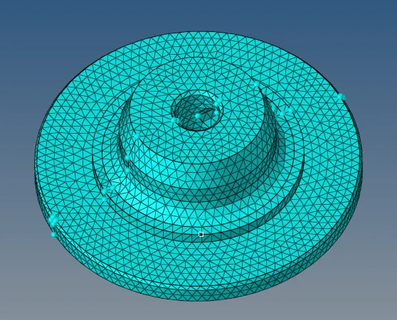
- Final image -- 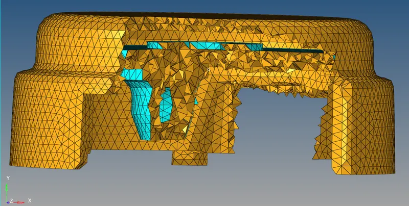
- CHECK FOR TET COLLAPSE
*F10--3D--tet collapse.
CONCLUSION :
> Reading and writing starter and engine file
> calculations related to it
> 3D offset, spin, linear solid, solid map.