Assignment 2-RADIOSS Engine File Editing & 3D Meshing Challenge
Questions:
1. Check the material properties of the rail component and calculate the speed of sound in steel rail=_______
Ans.
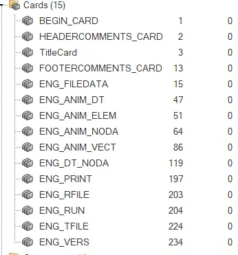
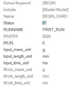
- To check the material properties first import the .rad file than go to cards - Open the file name with Begin_card - In the dropdown it will be showing the material properties with units check that all carefully as units are very important in calculations.
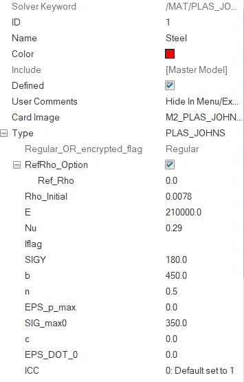
- Than Go to Materials - Steel which is already present there - Click on that - In the dropdown there will be the values of Youngs modulus(E), Density(Rho) mentioned there -From there take the values and covert that into required units and start calculating other values.

For calculating the speed of sound 'C' in steel rail,
C = √E/ρ
√2100/0.0078
*C=5188.74 mm/ms
where,
E-Youngs modulus 'Gpa' or 'Mpa' or 'N/mm2'
Rho(ρ) -Density 'g/mm3'
2. The length of the rail is about 1000 mm.calculate the time takes for a shock wave to travel from one end of the rail to the other.
∆t= L/C
=L/√E/ρ
however 'C' is calculated above substitute same value here and useng length value as 1000mm
= 1000/5188.74
*∆t=0.1927 ms
where,
C = √E/ρ mm/ms
L= length of element
E-Youngs modulus 'Gpa' or 'Mpa' or 'N/mm2'
Rho(ρ) -Density 'g/mm3'
3.Time for sound to travel length of rail=______
∆t= L/C
=L/√E/ρ
1000/5188.74
*∆t=0.1927 ms
4.Edit the engine file so that the stress wave can be monitored, moving from one end of the rail to the other during impact -this will require a termination time equal to the time it takes for the sound to travel the length of the rail(set on/RUN card)
Ans. Given,
Termination time (Ttermi)or Tstop = Time taken to travel the length of the rail( ∆t)
Ttermi = ∆t= L/C
= 1000/5188.74
*Ttermi = 0.1927 ms
where,
C = √E/ρ = 5188.74 mm/ms
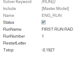
- After the whole calculation done Go to - Cards - ENG_RUN - Update the Tstop value with our answer that is Tstop or Ttermi = 0.1927 ms
5.Set the frequency of animation output to a time that will give 20 animation steps(/ANIM/DT)
Ans.
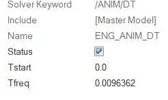
- First Go to cards - select ENG_ANIM_DT - in the dropdown there will be Tfreq - Go there and update the value with the calculated number by using formula as-
Tfrequency= Run time(Tstop)/No of anim steps
=0.192/20
=9.63*10-3
*Tfreq =0.00963
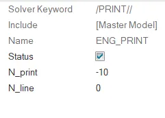
6.Change /print -10.
Ans. Go to Cards - ENG_PRINT -Change the N_print number =10
7. 3D MESHING CHALLENGES USING TETRA & HEXA MESH
Challenge 1 . Creating 1D Elements
Objective:
The main objective here is to create some 1D elements like RBE3, RBE2 , BARS on the given surfaces and save the model in .hm format.
Procedure:
- Primarily download the file from the skilllync website
- Open Hypermesh - File - Import - Model - Filetype - .Stp - Select the file from the computer - Import
- Press 'F' to Fit the model in hypermesh user interface area
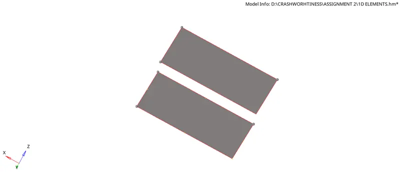
- There will be two models ther one model with surface and other model with only lines
- Select the model with lines and Go to Geo - Surfaces - Create surfaces by - using Line list - create the surface

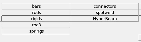
- Than Go to 1D - RBE3 - Dependent nodes - Calculate nodes - select independent nodes - create with All DOF ticked
- By using Calculate nodes the mass will be calculated and shared to all the nodes equally by the centre node
- After creating RBE3 elements go to

- 1D - Rigids- Create - Element type - RBE2 -Select primary node - node 2 n - select second node - mention Dof - create
- We can also update DOF , Connectivity , Element types etc.. and here also we can use calculate nodes and share the mass to all the nodes

- For next element Go to 1D - Rigids - Element type - RBODY - Select primary node - node 2 n - select second node - mention Dof than - create
- Like this we can create Bars , Beams , Trusses , Rods etc.. with our required DOF's and specified masses and weights
- Than Save the model by File - Save as - Select a Location to save - specify the name - save
Conclusion:
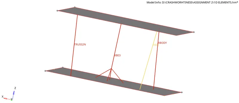
Finally creating the 1D elements on the given model is successfully completed with necessary criteria
Challenge 2 . 3D Meshing on Housing component
Objective:
The main aim in this challenge is to mesh the HOUSING Component using 3D TETRA Elements.
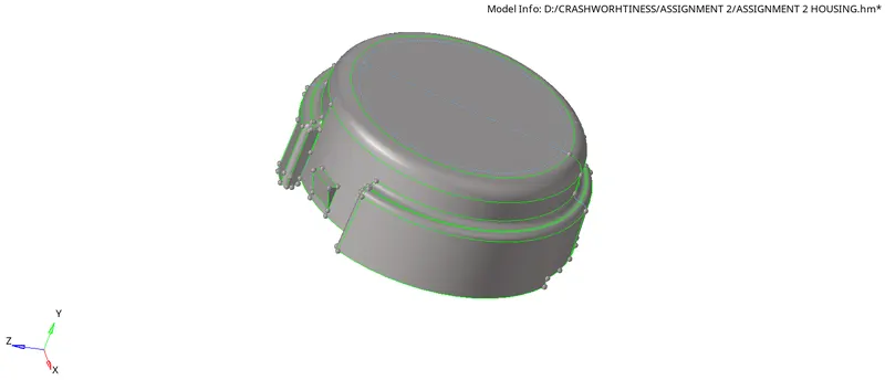
Given,
Target tet size=5mm
hex size=10mm
tet collapse=0.15.
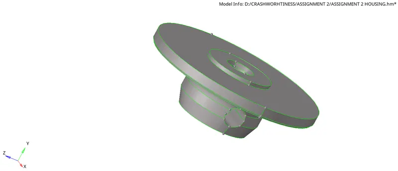
Procedure:
- Open Hypermesh - File - Import - Model - Filetype - .Stp - Select the file from the computer - Import
- Press 'F' to Fit the model in hypermesh user interface area
- Now examine the whole model once than
- Select a model and make it as Current than Go to 2D - Automesh - select element size = 5mm - Eelement type = Trias only - Select the whole model surface - Hit on Mesh

- Now Go to - 3D Panel - Tetramesh - in the Tetramesh parameters edit - Tet. collapse value to 0.150

- After this directly Go to Tetramesh - Select elements - Select displayed elements - Simple pyramid - Hit Mesh

- By doing so tetra mesh will be created on the model
- Now for checking the tet mesh creation Go to Tool - Mask - Elements - select few elements with left click - By meshing we can directly see the mesh is filled with 3D elements inside - than hit return and
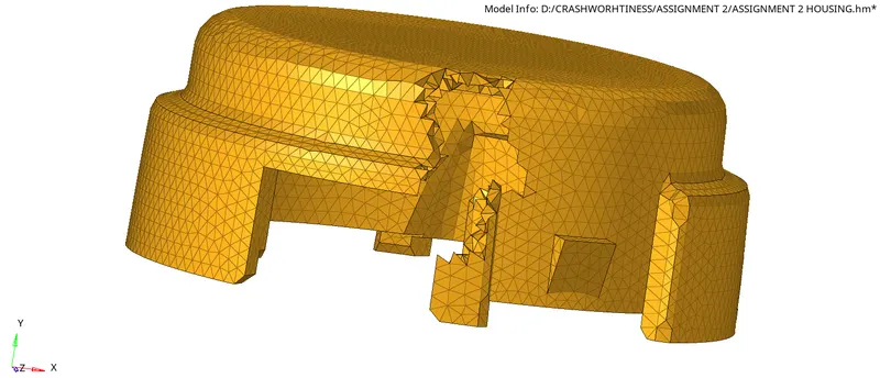
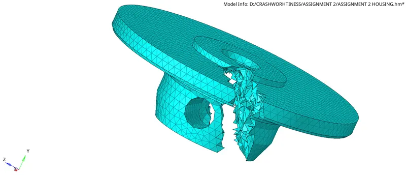
- Go to Tool - Check elements - 3D - Tet. collapse failure values - click on that - if the failed ones are zero than the model passed with quality parameter of tet. collapse
- Repeat the same steps for Model 2 also as 3D tetra mesh will be formed on the model.
- Than go to File - Save as - Select the file location -Save the model.
Conclusion:
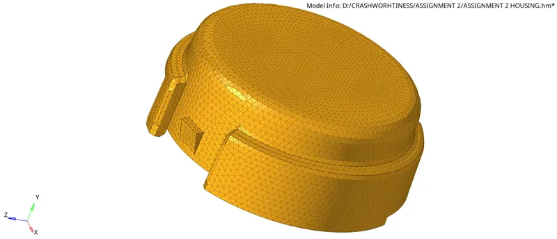
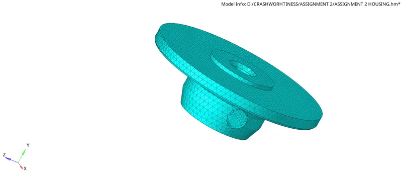
Finally by following the whole procedure serially we will get a model totally 3D meshed with tetra elements and with good quality without any Tet. collapse.
Challenge 3 . 3D Meshing on Arm Bracket with hexa elements
Objective:
The main aim in this challenge is to mesh the ARM BRACKET Component using 3D Hexa Elements .
Procedure:
Model 1 & 2:
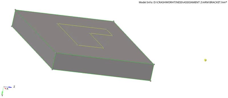
- Here in this model 1 & 2 primarily make that as current component
- Than Go to 2D -Automesh - Select surface -
Element type = Quads
Element size = 10 - Mesh the 1 & 2 model surfaces
- After meshing with 2D Quad elements Go to 3D - Element offset - Solid layers - Elements to offset -Select elements -
- Select along geometry to Follow - select all neighbouring surfaces on which elements should be
- Mention No. of layers = 5 - This should be mentioned after checking the distance (F4)
- Total thickess = 25 - Now Offset+ or Offset- according to the elements need on surface

- By this we will get model 1 & 2 surfaces meshed with Hexa elements - check that by masking the elements
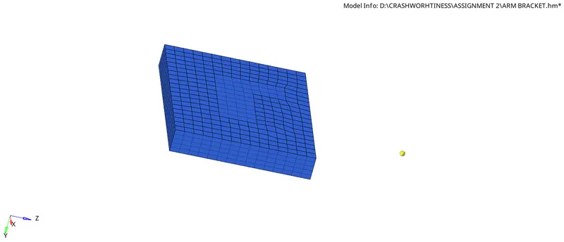
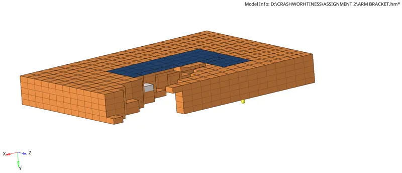
Model 3:
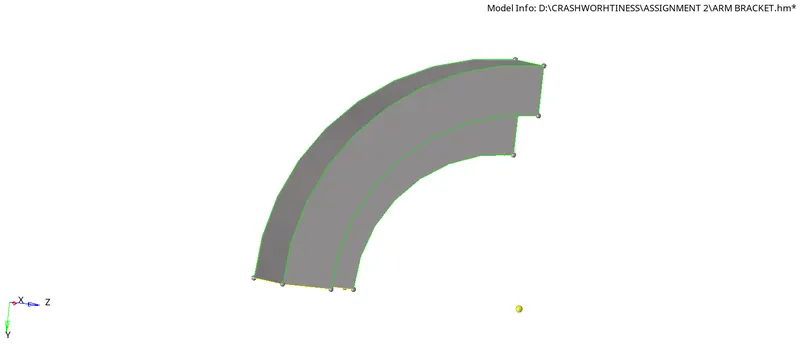
- After Meshing Model 1 & 2 switch on the model 3 that is Arm curve and analyse that as how to mesh
- After analysis we can get to a conclusion that as it is curved region we should use Spin elements from 3D panel
- Before that hide the 3D elements of Model 1&2 by Going to Tool - Mask - Select elements - (By config) - Select Hex8 from there - Select entities and mask them

- Than we will have only 2D Elements which can be used for meshing model 3
- Now Go to 3D -Spin - Spin elements - Select the 2D elements -
- For 3D element faces by nodes - use X axis and a base node
- But before we need to create a centre node by Going to Distance(F4) - Three nodes - Select a line with left click and hold till the line gets highlighted and select the three nodes on that line and select option circle centre which creates a centre for the circle which is used as Base node.

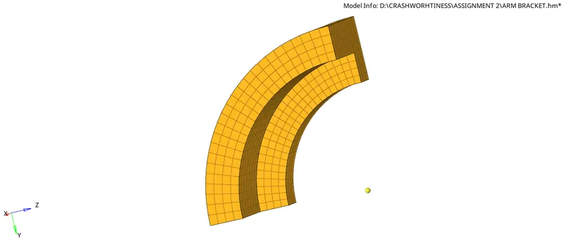
- After creating centre again go back to Spin elements - Select 2D elements - than mention angle as 90 - On spin = 25 - Select the base node - Spin+ or Spin-

- By this we can get 3D Hexa elements on the Arm curve than go to next models
- Finally the Model 3 after Hexa mesh will look like this -
Model 4:
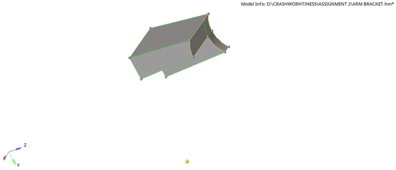
- Now in model 4 start by as it has also same cross-section but with decreasing area - Go to linear solid
- Before starting 3D meshing mesh the other side with 2D meshing but with same no. of Elements & nodes as exactly the mesh should match.
- Than start 3D hexa meshing by going to Linear solid - Select From Elements
- But for selecting From elements we should create the before hexa mesh to faces that are in 2D by going to
- Tool - Faces - Comps - Select the model 3 - Find faces - than use this face elements for 3D meshing

- Go to 3D - Linear solid - select From elements on the previous model faces and to Elements - with other side elements
- Density = 12
- Select the three nodes on one corner element and also same type of nodes on To elements and - Create Solids

- Than Delete the Faces which are created after Hexa meshing on the model
- Finally the Hexa mesh model looks like this-
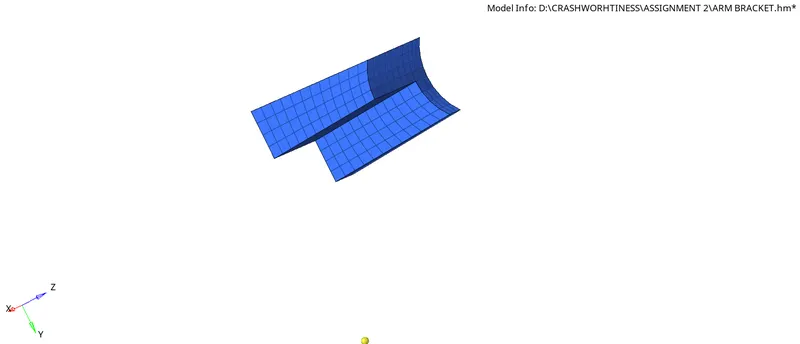
Model 5:
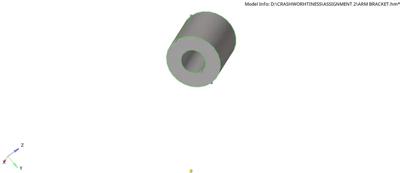
- Here first on one side of Cylindrical surface 2D mesh with equal number of elements and maintain same number of nodes on both inner & Outer surfaces.
- Than Go to 3D - Solid map -
- Source geo- none
- Select elements to drag - By face
- Dest geo - Select the destination surface
- Along geo - Lines - Select the Lines how the mesh should flow
- Along size = 10

- Finally Delete the 2D elements by using Delete - Delete elements - By Config - Hex4(2D elements) - Delete
- Finally the meshed Hexa model will look like this
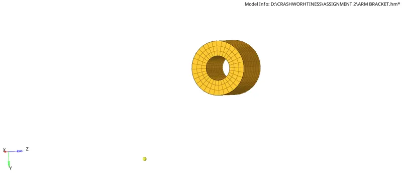
Conclusion:
Finally after doing each and every operation as above discussed in step by step manner we can get the ARM BRACKET model with 3D Hexa meshed as below which can be cross verified by Masking the elements and can be checked for Hexa mesh. The Final whole component after meshing looks like -
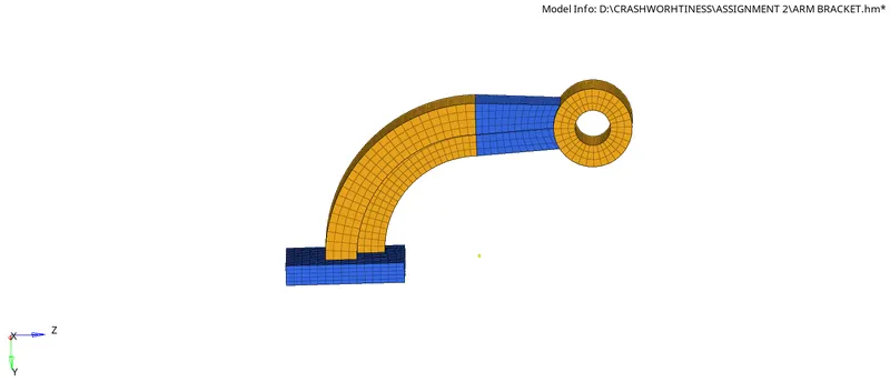
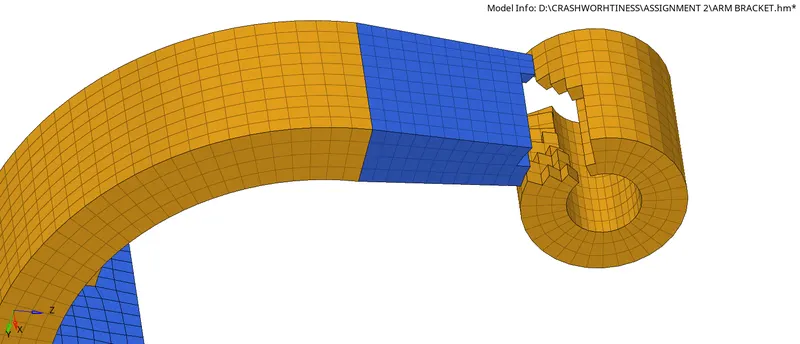 *Masked some elements for proper view of Hexa elements on Final model
CHALLENGE 4. CALCULATION OF RAIL COMPONENT
Objective:
The main aim here is to calculate Total time to travel from one end to other , Speed of sound 'C' , Tfreq , Ttermi etc.. and update all this values in given .rad File
Procedure:
- First of all start the claculations by checking the questions asked -
- See what are the values which are given in question and the values to be found
- Also for updating this values which we got it should be done in .rad file for that
- First - Import the .rad file as-
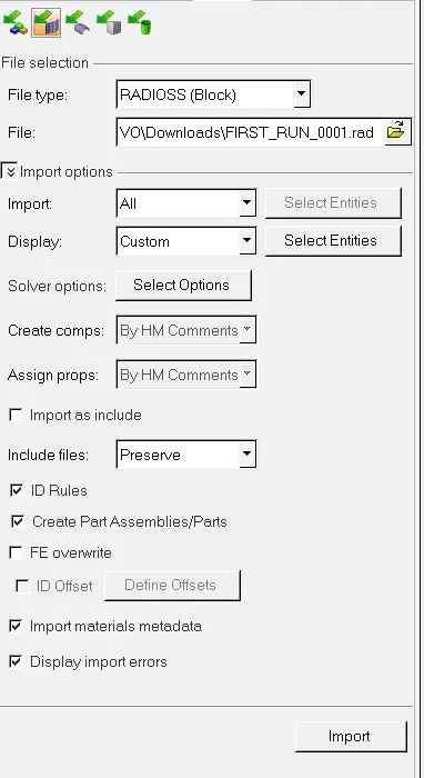
- File - Import - Solver deck - First Run Rad - there will be file mentioned in .rad format - Click Import - Import that model and start updating the values in that file only and attest the file which is in .hm after completion of execution
- The .rad model after importing looks like this
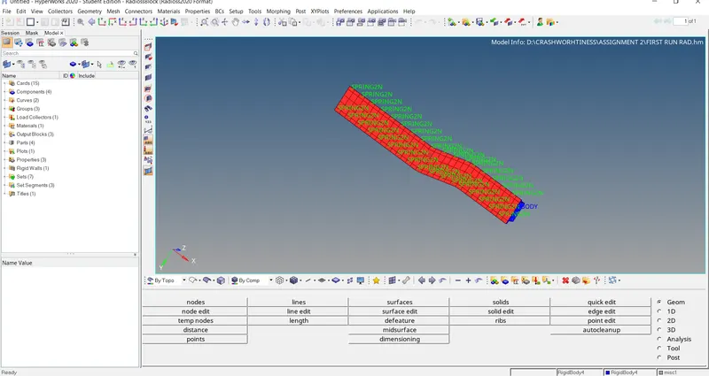
- Start solving questions one after the other as-
1. Check the material properties of the rail component and calculate the speed of sound in steel rail=_______
Ans.
- To check the material properties first import the .rad file than go to cards - Open the file name with Begin_card - In the dropdown it will be showing the material properties with units check that all carefully as units are very important in calculations.
- Than Go to Materials - Steel which is already present there - Click on that - In the dropdown there will be the values of Youngs modulus(E), Density(Rho) mentioned there -From there take the values and covert that into required units and start calculating other values.
For calculating the speed of sound 'C' in steel rail,
C = √E/ρ
√2100/0.0078
*C=5188.74 mm/ms
where,
E-Youngs modulus 'Gpa' or 'Mpa' or 'N/mm2'
Rho(ρ) -Density 'g/mm3'
2. The length of the rail is about 1000 mm.calculate the time takes for a shock wave to travel from one end of the rail to the other.
∆t= L/C
=L/√E/ρ
however 'C' is calculated above substitute same value here and useng length value as 1000mm
= 1000/5188.74
*∆t=0.1927 ms
where,
C = √E/ρ mm/ms
L= length of element
E-Youngs modulus 'Gpa' or 'Mpa' or 'N/mm2'
Rho(ρ) -Density 'g/mm3'
3.Time for sound to travel length of rail=______
∆t= L/C
=L/√E/ρ
1000/5188.74
*∆t=0.1927 ms
4.Edit the engine file so that the stress wave can be monitored, moving from one end of the rail to the other during impact -this will require a termination time equal to the time it takes for the sound to travel the length of the rail(set on/RUN card)
Ans. Given,
Termination time (Ttermi)or Tstop = Time taken to travel the length of the rail( ∆t)
Ttermi = ∆t= L/C
= 1000/5188.74
*Ttermi = 0.1927 ms
where,
C = √E/ρ = 5188.74 mm/ms
- After the whole calculation done Go to - Cards - ENG_RUN - Update the Tstop value with our answer that is Tstop or Ttermi = 0.1927 ms
5.Set the frequency of animation output to a time that will give 20 animation steps(/ANIM/DT)
Ans.
- First Go to cards - select ENG_ANIM_DT - in the dropdown there will be Tfreq - Go there and update the value with the calculated number by using formula as-
Tfrequency= Run time(Tstop)/No of anim steps
=0.192/20
=9.63*10-3
*Tfreq =0.00963
6.Change /print -10.
Ans. Go to Cards - ENG_PRINT -Change the N_print number =10
- After all these finally Go to Analysis panel - Select Radioss - Select the File location as where you want store the file - Check Include connectors - Radioss

- After clicking on Radioss - The result of Analysis looks like this -
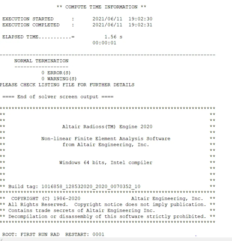
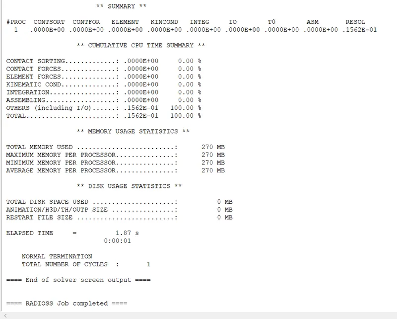
- There will be some files & Programs which will be running in background and some files will be stored in the storage location where the Model file(.hm) is present
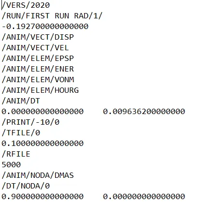
- Among those program files Engine File is one of the important which contains the values which are given by us like Ttermi , T freq , Total time etc...
- The Engine file wih actual values looks like this -
Conclusion:
By calculating we get the various values which should be updated in the given .rad model by which we get the Radioss report and also Engine File snipset.