Assignment 2-RADIOSS Engine File Editing & 3D Meshing Challenge
OBJECTIVE :
1. Check the material properties of the rail component and calculate the speed of sound in steel rail.
2. The length of the rail is about 1000 mm.calculate the time takes for a shock wave to travel from one end of the rail to the other.
3.Time for sound to travel length of rail.
4.Edit the engine file so that the stress wave can be monitored, moving from one end of the rail to the other during impact -this will require a termination time equal to the time it takes for the sound to travel the length of the rail(set on/RUN card)
5.Set the frequency of animation output to a time that will give 20 animation steps(/ANIM/DT)
6.Change /print -10.
7.3d meshing tetra mesh and hex mesh
- Repeat class examples and, maintain the quality.
- Target tet size=5mm,hex size=10mm,tet collapse=0.15.
PROCEDURE :
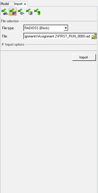
1. To check the material properties in the rail component we need to import the component initially. The component file seems to be .rad file so we can either open it up in the Notepad as it is an ASCII file or we can open it in the Hypermesh using Radioss import.
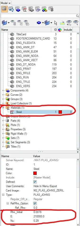
Or we can open it in notepad to check the material properties :
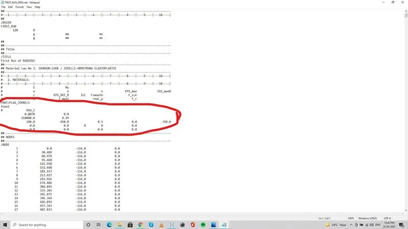
1. Check the material properties of the rail component and calculate the speed of sound in steel rail :
Speed of Sound ( C ) = `sqrt ((E)/(rho))`
E = Young's moulus (210Gpa = 2.1 x `10^11`N/`m^2`)
`rho` = Density of material 0.0078 g/mm3 = 0.0078 x`10^-3`Kg/`mm^3`
C = `sqrt (E /rho)`
Solution :
1N = 1Kg.1m/`s^2`
so, E = 2.1 x `10^11` x `10^-3`Kg/(mm.`s^2`)
`rho` = 0.0078 x `10^-3` Kg/`mm^3`
`sqrt (E/rho)` = 5188745.21 { (Kg/mm.`s^2`) / (Kg/`mm^3`)} ---> { mm /`s^2`} ---> `10^-3`{ mm/ms }
so, C = 5188745 x `10^-3` mm/ms
C =5188.745 mm/ms
2. Calculate the time takes for a shock wave to travel from one end of the rail to the other :
The Shock wave travels at the speed of sound.
The length of the rail is 1000mm ( given )
So, the time taken for the shock wave to travel 1000mm (1000mm) = '( Length / Speed )' = 1000/5188.745 = 0.1927 ms
3.Time for sound to travel length of rail :
Length of rail (1000mm) as calculated in previous question, The Time taken for the sound wave to travel across the length of rail is 0.1927 ms
4. To Edit the engine file so that the stress wave can be monitored, moving from one end of the rail to the other during impact :
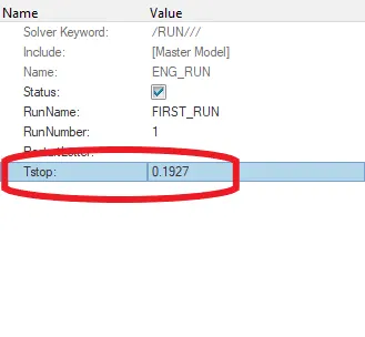
This should be done either in the Hypermesh by editing the ENG RUN card by editing the TStop value to the desired value which is calculated or it can be entered manually in Notepad by opening the file FIRST_RUN_0001.rad and entering the calculated value to the run time ( since the output requests and run time all were dealed in the engine file, 0001.rad file ( engine input file) should be opened and edited in notepad )
The value to be entered is 0.1927 (as calculated above)
Here, we are editing the value in the Hypermesh window as follows :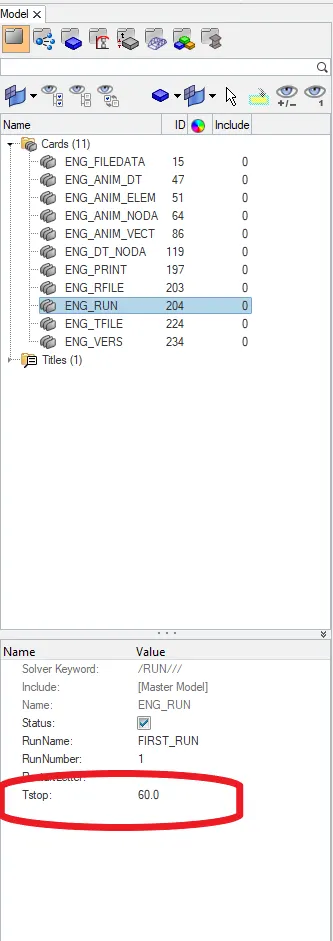
5. Set the frequency of animation output to a time that will give 20 animation steps(/ANIM/DT)
Frequency is defined as so many cycles in a given time period. One cycle per second is equivalent to 1 Hz.
So, for 20 cycles with a time of run as 0.1927ms, the frequency would be :
Frequency = 20/0.1927 = 103.78 `approx` 104 Hz
This can be entered in the Tfreq of ENG ANIM DT card in the Engine input file itself. Here is the edited value :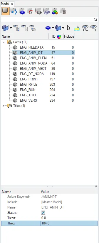
6. Change /print -10
In the ENG PRINT we can change the Print value. But the default value is already found to be -10. So no change is done to it.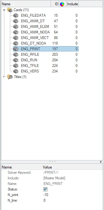
7. 2D meshing :
The given component has to be meshed with 2D elements and then the 1D elements of Beam, Truss and Springs has to be deployed in it.
Here is the given geometry :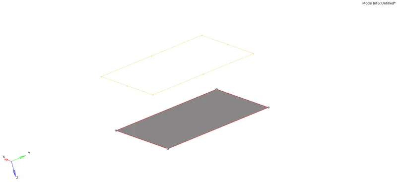
The surface can be created in the upper part using Surface >> Ruled option and then 2D mesh can be carried out using 2D >> Automesh >> Mixed elements. Once the meshing is done, the 1D elements, Truss, Beam and Springs can be deployed. For Truss, go to 1D >> Rods >> Select two nodes >> Select element type as Truss2N.
To create the cross section for the Truss element, Go to Hyperbeam >> standard section >> Standard H section >> Create.
It will open the Hyperbeam window where we can edit the cross sectional dimensions of the truss.
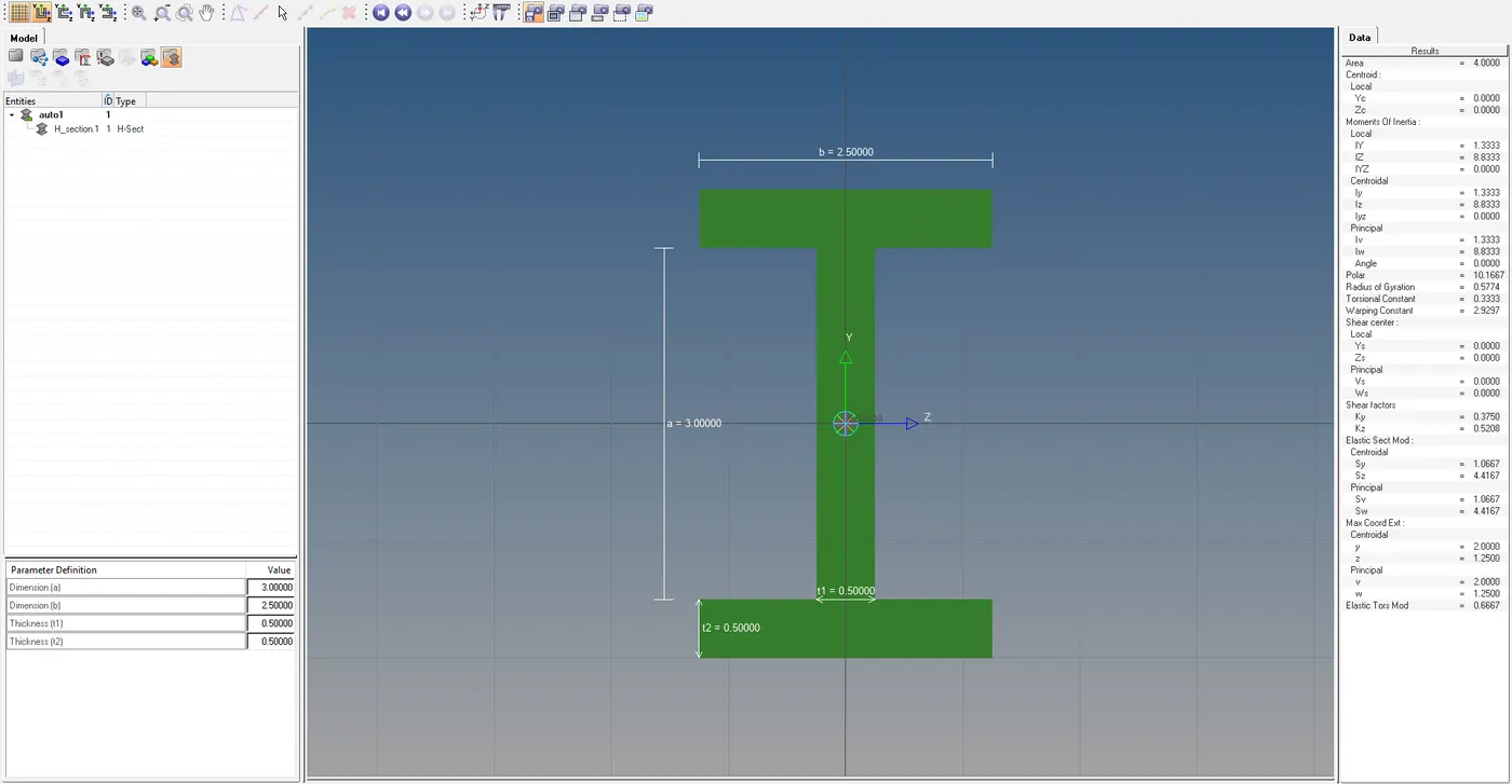
Now, create the Property for the truss element with Property as P2_TRUS and then update the Hyperbeam section to it which is created. Also the material can be created and assigned if there are any.
For the Beam creation use Bars option in 1D and Springs in 1D for spring element. Properties would be P3_BEAM & P4_SPRINGS.
Here is the Final output :
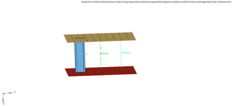
3D TETRAMESHING :
For the given component which is solid, we can either directly create the Volume mesh or we can use Quick Tetra from the Utilities tab or we can mesh them with 2D trias and then create 3D tetra elements on it.
Here we are following the third method.
1. Firstly, the Solids are deleted and the surface has to be checked for any topo repair. Since the geometry is free from any errors, It can be meshed with 2D trias.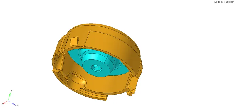
2. Now go to 2D automesh >> Select element type as Tria >> Mesh size as 5mm and select the geometry and mesh it. For both the parts 2D mesh has to be carried on.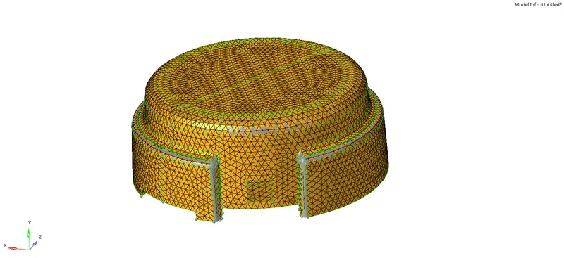
3. Once the 2D mesh is completed, go to 3D >> Tetra mesh >> Select all the 2D elements created >> set the tetra mesh size as 10mm and go to tetra mesh parameters tab to set Tet collapse value as 0.15
With all the parameters set, hit the mesh button to produce the Volume mesh.
The same procedure has to be carried over to the other part and once the Tetra mesh is completed, we can check the Tet collapse value and If there are any elements failing for tet collapse, those elements can be fixed with Translate tool in the Tools command. It is advised to check the elements after translate since it would provoke unnecessary kinks on the surface if the failed element is closer to the top surface.
The 2D elements can be deleted by using By Config >> Tria 3 elements in the Delete elements option.
Here is the final mesh model ( mask certain elements to check the tetra mesh ):
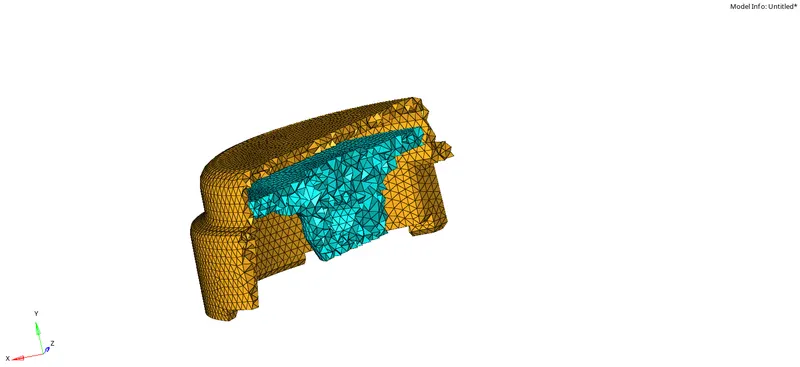
HEXAMESH :
For the given arm bracket, unlike the tetra mesh, the hexa mesh is quite complicated since we need to create only quads which needs to be mapped to the other surface to create the hexa / block elements inbetween. Since the given component has various parts, we can start off with the base as it is the most easier as compared to the others.
1. Firstly, mesh the top surface with quad elements and make sure there are no trias on it. So this needs to be meshed with quads of 10mm size.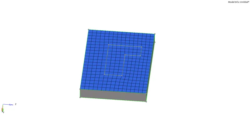
2. Now, go to 3D mesh >> Element offset >> Solid layers >> Select the top elements as the source (elements to offset) >> Select the surface to be followed to offset and Enter the no. of. layers as 5 ( as per requirement ) and click offset.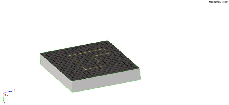
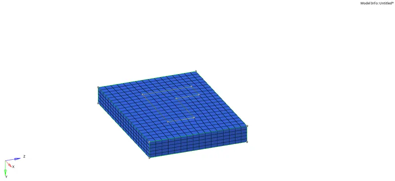
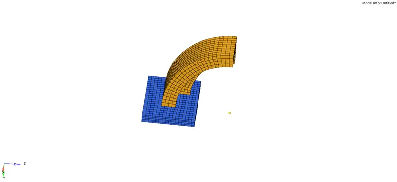
3. Now, for the next part, we have the base elements which need to be spin along its angle. So we need to have the base node to spin the elements. Go to Nodes >> Arc center >> select the curve line from the geometry and create the base node. Then go to 3D >> Spin elements >> Select the 2D elements in the top surface and set the vector to screen normal and select the base node which is created.
The angle of spin would be 90 deg and On spin ( as per requirement )as 25 and click spin to create the brick elements.
4. For the next part, we need 2D elements to match the other surface. So go to Checks >> Faces >> Create faces of the previously Spinned part and have the 2D faces of those brick elements. Now, mesh the other side of the next part which appears to be tapered in the dimension with 2D quad elements and match the no.of.elements in the previous part. Once the elements were matched, we can use linear solid option to match the elements and create the inbetween brick elements. 
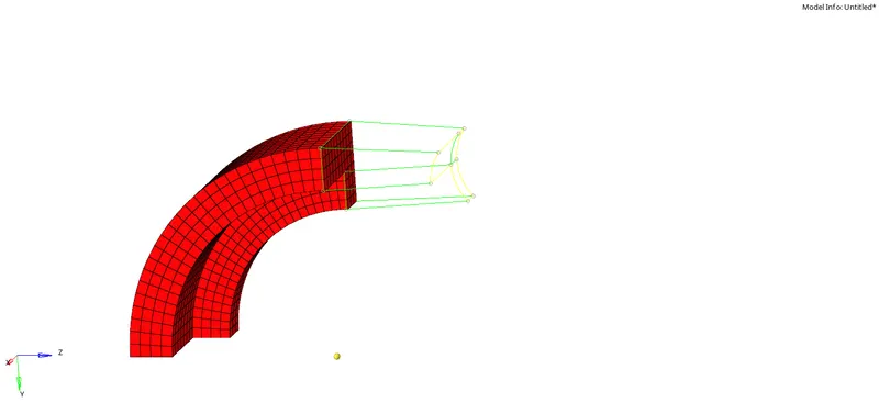
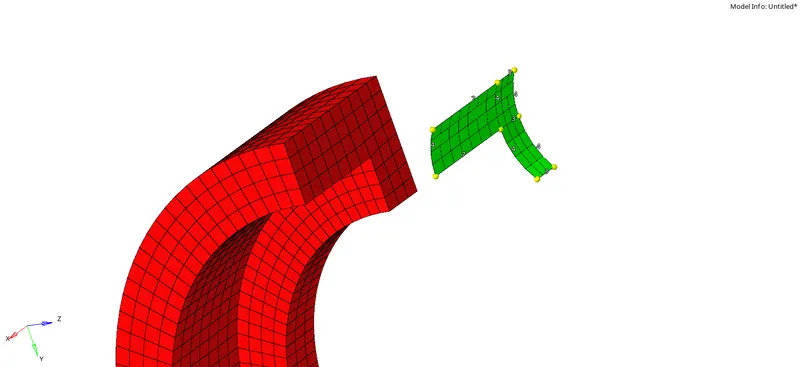
The node alignment and the selection of plane for the linear solid needs to be exactly same on both the surface.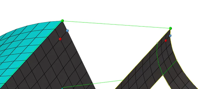
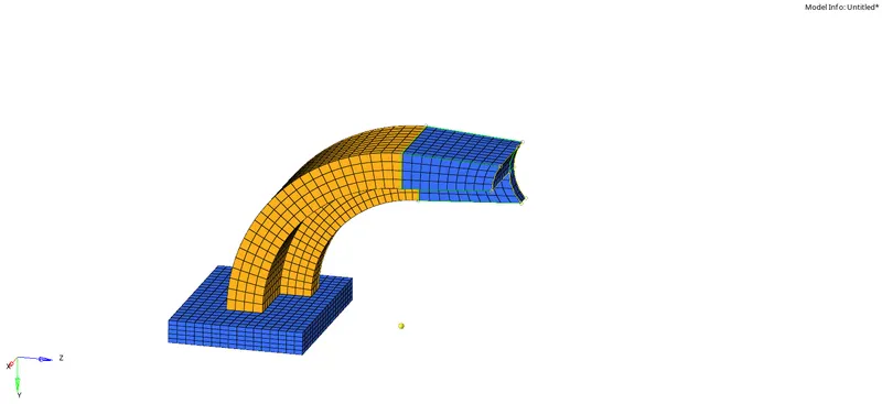
5. For the Final part, Mesh the top and bottom surface with similar no.of.nodes and make sure the connection between the previous part and the boss part is proper. We can project the points and extend the surface lines properly to create better guide path in order to solid map the elements along certain path.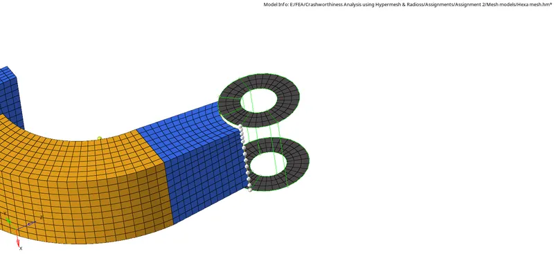
As in the above picture, mesh them with quad elements with same no.of.nodes on either side, and go to 3D >> Solid map >> Select the source elements to drag >> select the other side elements to match >> select the node path which explains the best of the feature and click mesh to create the brick mesh along the geometry.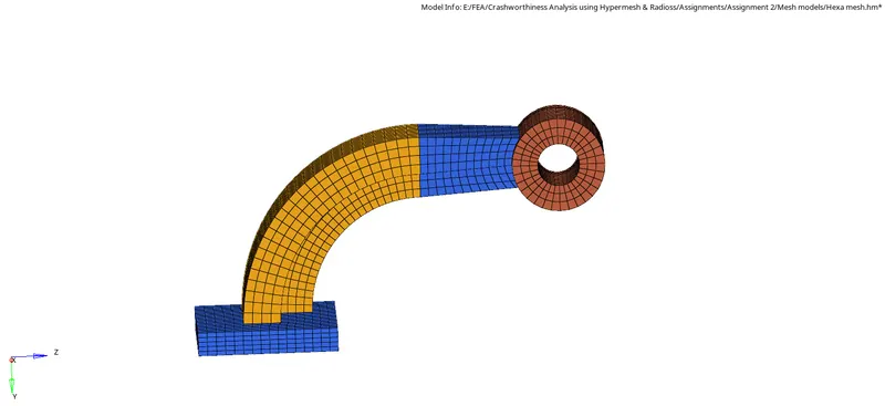
Once all the Hexa elements were created, we can delete the 2D elements by using By config option. Also we need to check the free edges and the element connectivity since the mapping of elements across such complex surface would provoke equivalence errors.
Thus the model has been meshed with proper Hexa elements.
RESULT & INFERENCE :
All the meshing has been carried out and all the input files to be changed in the radioss file has been done. From this exercise we learnt to deal with :
1. Calculations of Speed of wave, Time step, Tfreq values etc
2. Opening of Radioss starter and engine files and editing it.
3. Meshing of components in 2D and creating 1D elements in it.
4. Tetra mesh and Hexa mesh.