RADIOSS Engine File Editing & 3D Meshing
QUESTIONS:
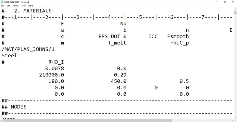
- Check the material properties of the rail component and calculate the speed of sound in steel rail-
E = 210000
Ρ = 0.0078
C = `sqrt`(E/Rho)
= `sqrt`(210000/0.00078)
C = 5188.745
- The length of the rail is about 1000 mm. Calculate the time takes for a shock wave to travel from one end of the rail to the other.
L = 1000mm
∆t = l/c
= 1000/5188.745
= 0.1927
- Time for sound to travel length of rail is 0.1927.
- Edit the engine file so that the stress wave can be monitored, moving from one end of the rail to the other during impact -this will require a termination time equal to the time it takes for the sound to travel the length of the rail(set on/RUN card)
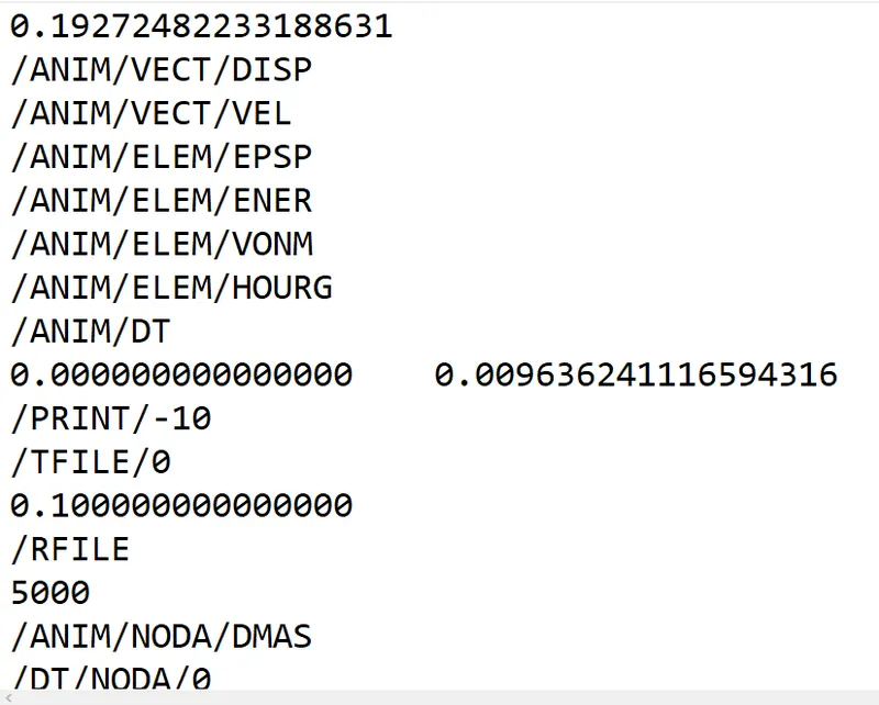
- Set the frequency of animation output to a time that will give 20 animation steps(/ANIM/DT)
Freq = 0.1927/20
= 0.009636
- Change /print -10.
AIM:
- To understand the radios input and output files, engine files, time and length calculations. To understand the tools in radioss used for 3D tetra and Hexa meshing of the components.
OBJECTIVES OF THE PROJECT:
- To calculate the speed of time for steel material.
- To calculate the time taken for the shock wave to travel through a material.
- To understand the configuration and coding of the Radioss engine files.
- To understand the 3D tetra and hexa meshing tools.
PROCEDURE:
- MODEL: 1D_ELEMENTS
- First step is to import the model in the Hypermesh Radioss profile.
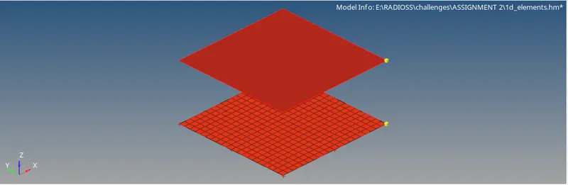
- Go to FILE > IMPORT > MODEL > BROWSE > OPEN > OK.
- Now, for the 1D model we have to mesh the surfaces with quad elements.
- For meshing go to 2D > AUTOMESH > MESH SIZE = 0.5 > MESH TYPE = MIXED > SELECT THE SURFACE > MESH.
- Now, the main objective is to deploy 1D connection.
- Go to 1D > RIGIDS > CREATE > NODE LIST > ELEMENT TYPE = RBODY > CREATE.
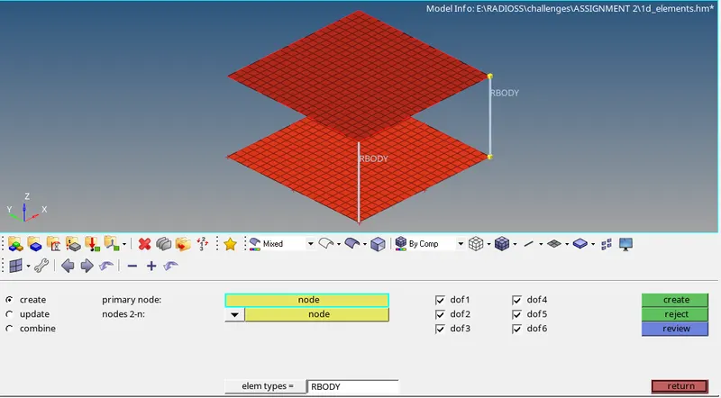
- Now, for creating RBE3 connections go to 1D > RBE3 > CREATE > NODE LIST > CREATE.
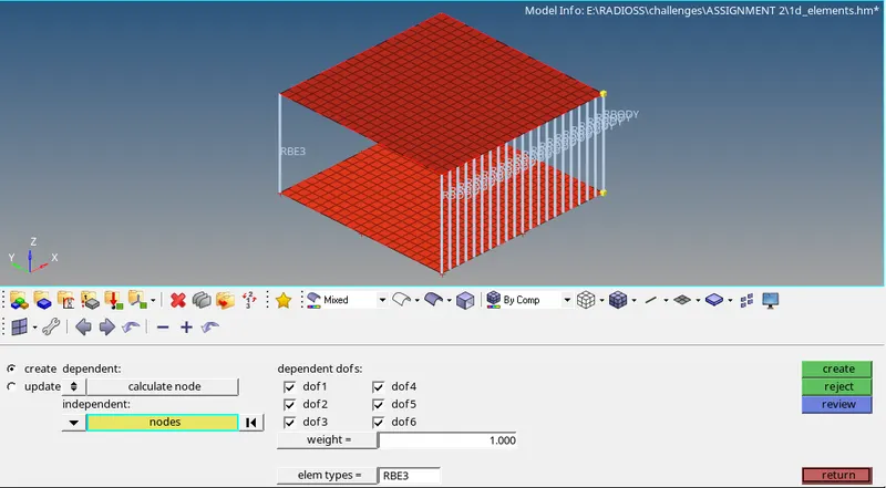
- Now, for creating spring elements go to 1D > SPRINGS > SPRING2 > NODE LIST > CREATE.
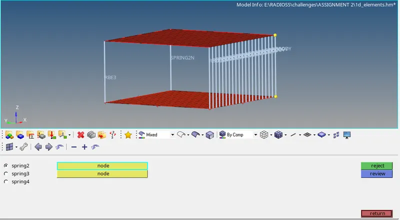
- Hence, the 1D connections are deployed.
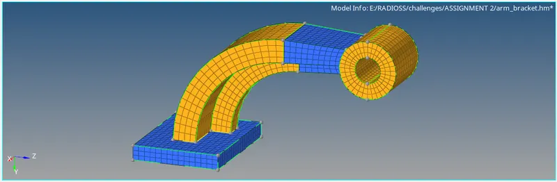
- MODEL: ARM BRACKET
- First step is to import the arm bracket model in the Hypermesh radios profile.
- Go to FILE > IMPORT > MODEL > BROWSE > OPEN > OK.
- Now, we have to mesh the model with Hexa elements.
- Switch off all the component geometry other than base geometry.
- Go to 2D > AUTOMESH > ELEMENT SIZE= 10 > ELEMENT TYPE = MIXED > SELECT THE BASE SURFACE > MESH.
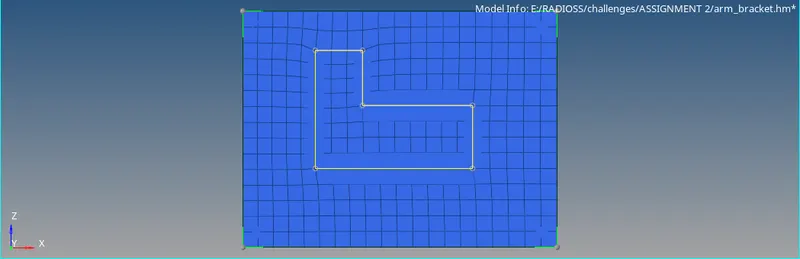
- Now, to convert this shell elements to hex elements go to 3D > LINE DRAG > DRAG ELEMENTS > ELEMENTS > BY FACE > ALONG – LINE > ON DRAG = 3 > DRAG.
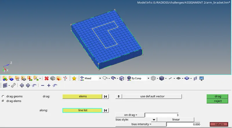
- This will drag the 2D elements along the line and create 3D hex elements.
- Now for the curved body create a node for base point by GEOM > NODES > ARC CENTER . LINES > SELECT LINE > CREATE.
- Now, go to 3D > SPIN > SPIN ELEMENTS > SELECT ELEMENTS > ALONG X AXIS > BASE POINT > ON DRAG = 20 > SPIN –
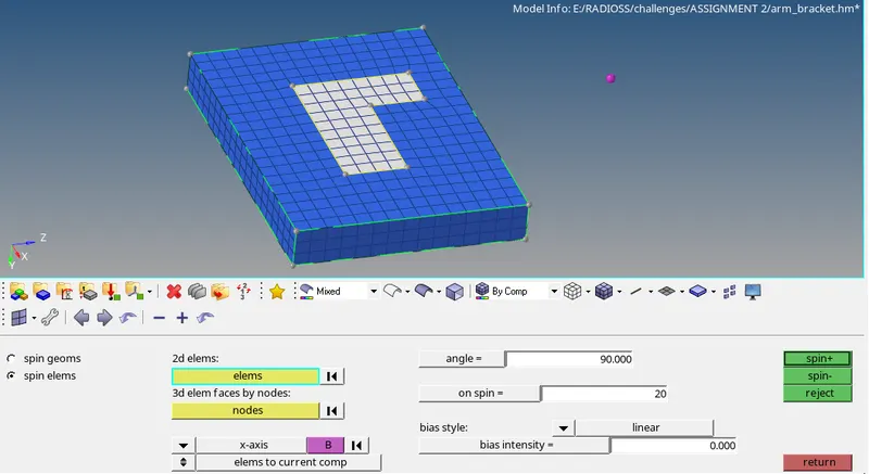
- This will spin the elements along the body and create 3D hex elements.
- Now, for the arm section we require a reference face to match the elements. Hence to obtain the face go to TOOL > FACES > COMPONENTS > BODY > EXTRACT FACES.
- Now, go to 2D > AUTOMESH and mesh the arm boss end surface in relevance to the body face.
- Then go to 3D > LINEAR SOILDS> FROM: ELEMENTS > TO: ELEMENTS > SELECT ALIGNMENT > DENSITY = 10 > SOLIDS.
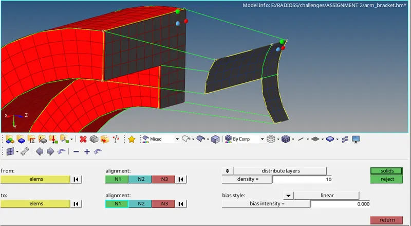
- This will match the face elements to the meshed elements and create 3D hex elements.
- Now, for the boss section go to 2D > AUTOMESH and mesh the plain surface in accordance with the arm element number.
- Then go to 3D > SOLID MAP > GENERAL > SOURCE GEOM > DEST GEOM > NODE LIST > ELEMENTS > BY FACE > MESH.
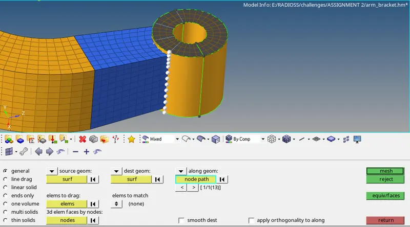
- This will complete the 3D hexa meshing of the arm bracket.
- Now, for deleting the 2D shell elements go to DELETE > ELEMENTS > BY CONFIG > QUAD4 > SELECT ENTITIES > DELETE.
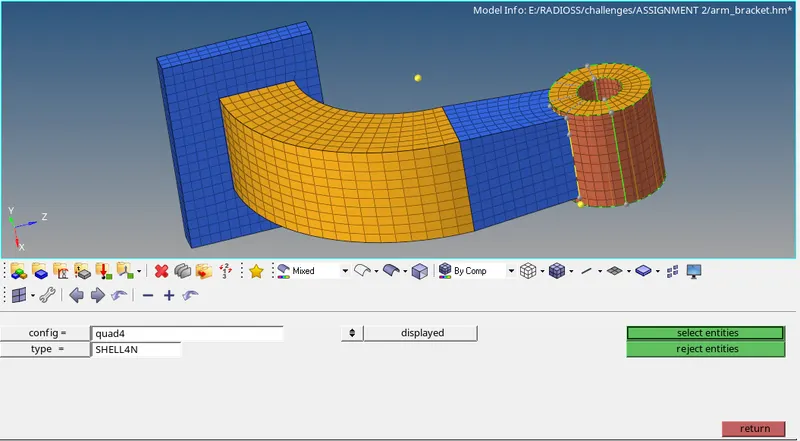
- Now, the model consists of only the HEX elements.
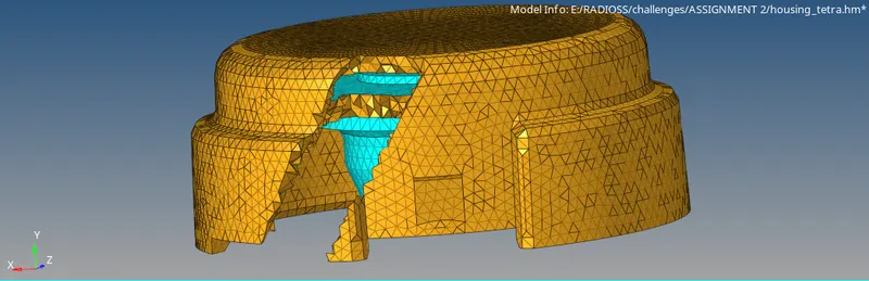
- MODEL: HOUSING
- First step is to import the arm bracket model in the Hypermesh radios profile.
- Go to FILE > IMPORT > MODEL > BROWSE > OPEN > OK.
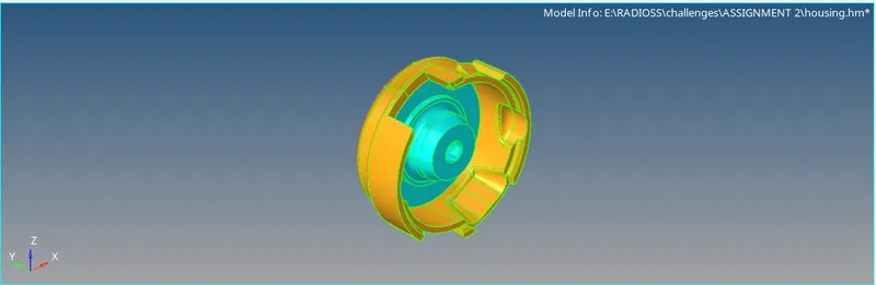
- Now, we have to create 3d tetra mesh on the model.
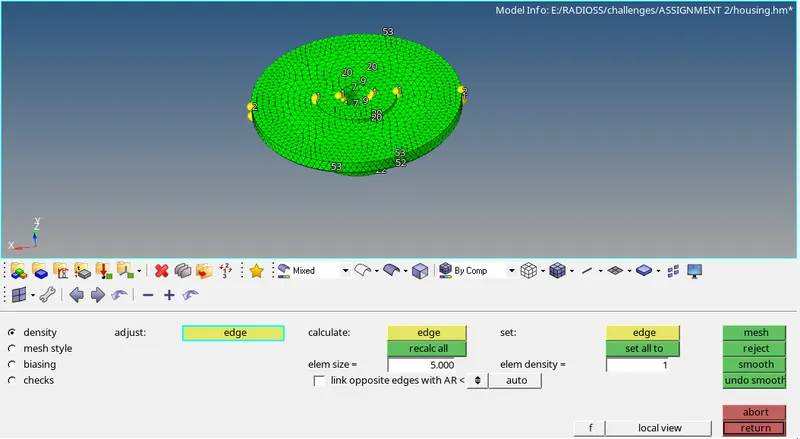
- Go to 2D > AUTOMESH > ELEMENT SIZE= 5 > ELEMENT TYPE = TRIAS > SURFS > DISPLAYED > MESH.
- Then go to 3D > TETRAMESH > TETRAMESH PARAMETERS > TET COLLAPSE = 0.15 > TETRAMESH > ELEMENTS > DISPLAYED > MESH.
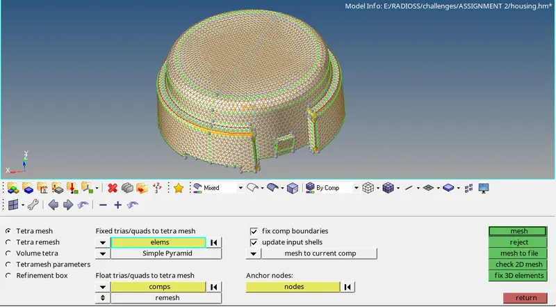
- This will create 3D volume tetra meh throughout the component.
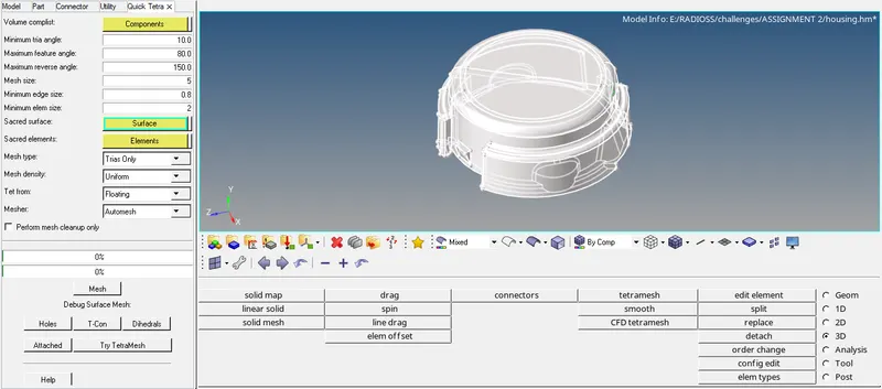
- You can also use the QUICK TETRA option as shown below.
- Now, to check the elements failing for tet collapse, go to TOOL > CHECK ELEMENTS > 3D TET COLLAPSE.

- Hence, the model is meshed with 3D tetra elements.
RESLUTS:
LEARNING OUTCOMES:
- To calculate the sound speed for the material.
- To calculate the time travel of shock wave.
- To deploy 3D tetra mesh.
- To deploy 3D hexa mesh.
- To use the 3D tools for tetra and hexa Mesh.
CONCLUSION:
- Hence, by performing this project we conclude that the models are meshed with the 3D tetra and hexa elements.