EDITING OF ENGINE FILE AND 3D MESHING (TETRA AND HEXA) OF COMPONENTS
EDITING OF ENGINE FILE AND 3D MESHING (TETRA AND HEXA) OF COMPONENTS
OBJECTIVE:
- To calculate the speed of the sound through the rail according to the provided material properties.
- To calculate the time taken by the sound to travel through the element.
- Editing of the engine file to monitor the stress wave, set the frequency of animation steps and to change the print.
- 3D mesh the given components according to the below mentioned criteria.
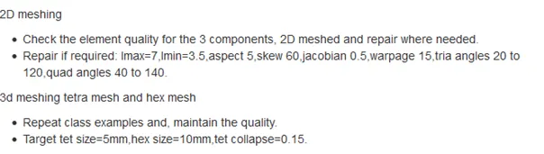
Fig: Criteria.
PROCEDURE:
1. Check the units and properties of the provided starter file as shown. The units are in gm, mm, ms. And the properties E=210000Mpa, Rho=0.0078 gm/mm³.
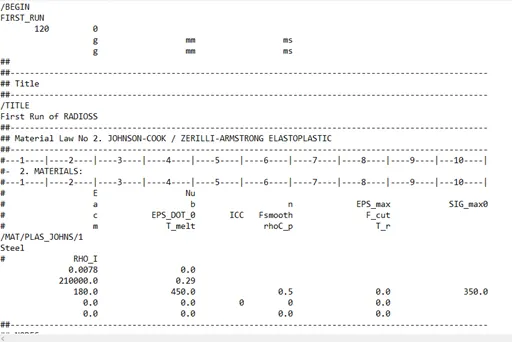
Fig: Starter file.
2. To calculate the speed of sound C= √ E/ſ , where E = Young’s modulus, ſ= Density.
C = √ E/ſ
= √(210000*10³/0.0078*10³)
= 5188.7452 mm/ms.
3 .To calculate the time taken by the shock wave to travel through the length of 1000mm.
∆Tc = L/C , Where L = Length, C= Speed of sound.
= 1000/5188.7452
= 0.1927 ms.
4. To calculate the time frequency.
Tf = ∆Tc/ N, N = No. of time steps.
= 0.1927/20
= 0.00963 ms.
5. Enter the calculated values by importing the starter file to Hypermesh. Enter the above calculated values to their respective cards as mentioned and export the solver deck model.
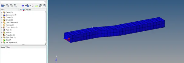
Fig: Imported solver deck file.
3D MESHING
6. Open the provided housing model for tetra mesh.
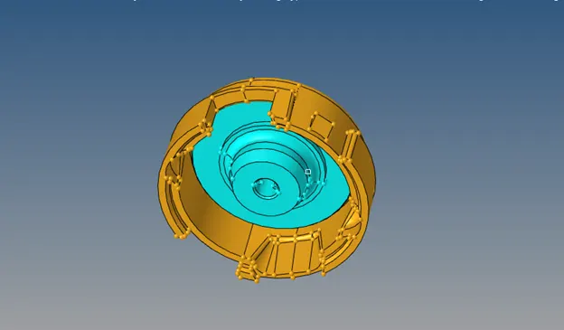
Fig: Imported model.
7. Check for any geometry errors. If found fix it, check for solids and if found delete.
8. Set cover component as current component and mesh the component with volume tetra option.
9. Set the tetra mesh parameters from 3D tab and select the surfaces, set the target tet size to 5mm and mesh.
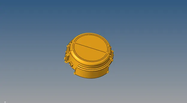
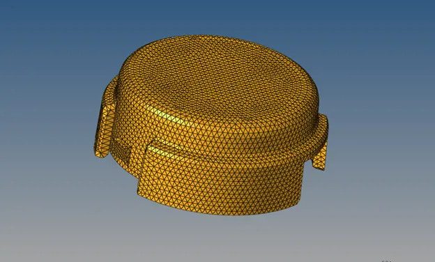
Fig: Tetra meshing.
10. Repeat the same steps for the hub part and check for tet collapse from quality check tab.
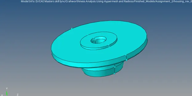
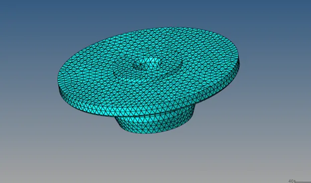
Fig: Tetra meshing.
11. Open the arm bracket model and perform the geometry checks.
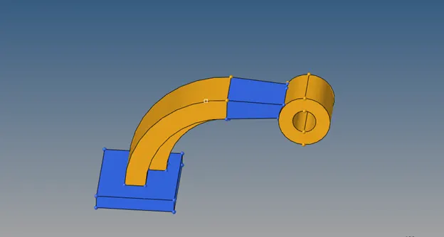
Fig: Imported model.
12. Since the parts are in separate components hide the unnecessary parts and start meshing of base with 10mm quad only elements as shown.
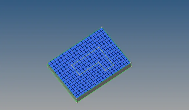
Fig: 2D Surface mesh.
13. To convert the 2d mesh in to hexa mesh go to 3D and offset the element, select the faces and elements, enter number of layers to 3 and offset.
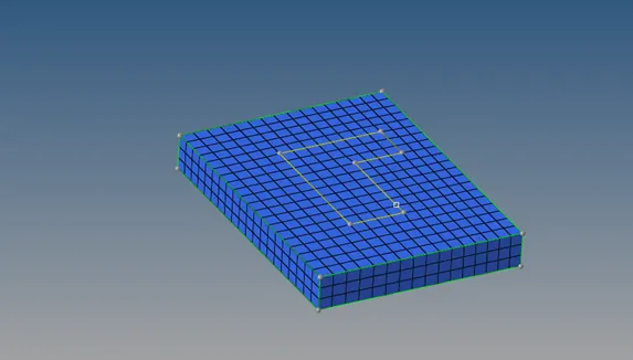
Fig: Volume mesh. (Hexa)
14. To mesh the arm curve go to linear solid and select line drag, select the elements and curve and set the element size to 10 and drag.
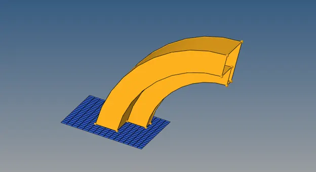
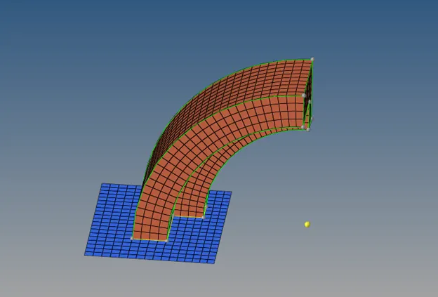
Fig: Line Drag.
15. Organize the elements to the original geometry.
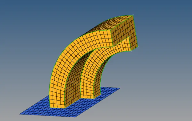
Fig: After organizing the mesh.
16. To mesh the arm straight create 2D elements on the end face so that they are equal in numbers to the other end elements. Create face for the arm curve component in order to create 2D elements. After hexa meshing delete the faces.
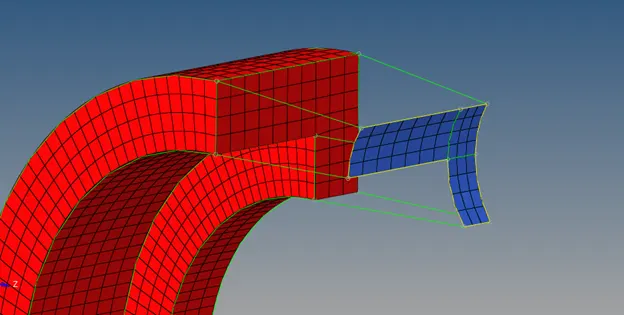
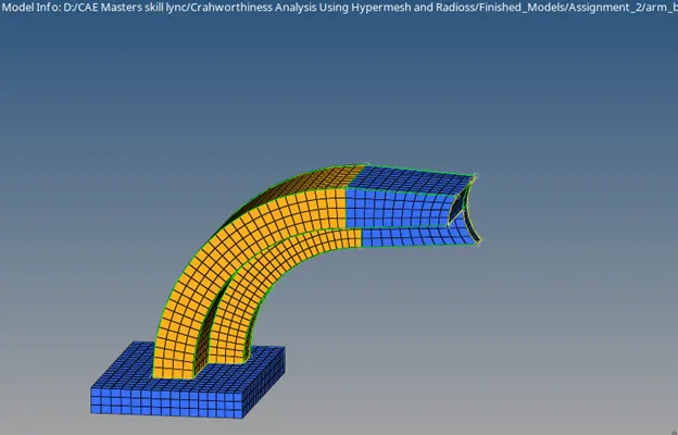
Fig: Meshing of arm straight.
17. For hexa meshing select linear solid and select the sets of elements and identical node locations.
18. To mesh the Boss part off set a node to the below surface and mesh the top surface using 2D elements with equal number of nodes.
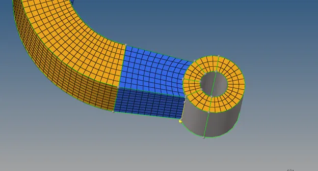
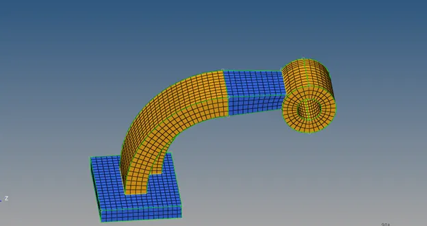
Fig: Meshing of Boss.
19. Using solid map general options select the target surfaces and node paths to create hexa elements.
20. Delete the 2D elements using by Config filter.
RESULT:
1. The speed of the sound is found to be 5188.7452 mm/ms.
2. The time taken by the shock wave to travel 1000mm is found to be 0.1927 ms.
3. The time frequency is found to be 0.00963 ms.
4. The calculated values were entered in the Engine file.
5. The given Models were meshed according to the specified parameters and no tet collapse failures were found.
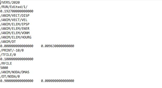
Fig: Edited Engine file.
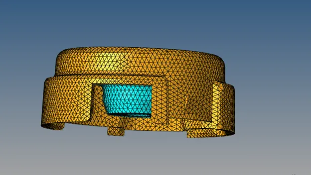
Fig: Final Model.