Assignment 2-RADIOSS Engine File Editing & 3D Meshing Challenge
Aim:
To study about the starter file and engine file in RADIOSS by changing the parameters for the given file. And also perform a 3D meshing on the given components of which one will have tetra mesh and the other one will have hex mesh.
Objective:
- Check the material properties of the rail component and calculate the speed of sound in steel rail=_______
- The length of the rail is about 1000 mm. Calculate the time takes for a shock wave to travel from one end of the rail to the other.
- Edit the engine file so that the stress wave can be monitored, moving from one end of the rail to the other during impact - this will require a termination time equal to the time it takes for the sound to travel the length of the rail (set on/RUN card).
- Set the frequency of animation output to a time that will give 20 animation steps(/ANIM/DT).
- 3D meshing - tetra mesh and hex mesh.
Target Tet Size = 5 mm, Tet collapse= 0.15, Hex Size= 10 mm..
- Solution:
- 1. Check the material properties of the rail component and calculate the speed of sound in steel rail=_______
- So to check the material properties of the material of the rail component. We have to import the component in the hypermesh.
- We have the ".rad" file. So for that, the profile should be RADIOSS.
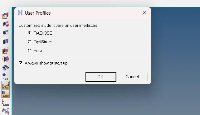
- Now we will go to the import option. There we are going to select the 0000.rad file and import it.
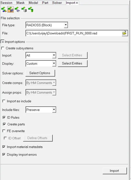
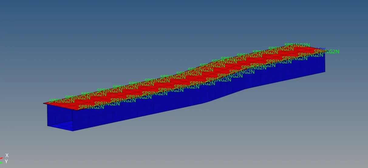
fig below is the rail component
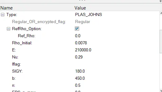
- Now we will go to material property and check the values. we can see the density and Young's Modulus of steel under Material property in Model browser window
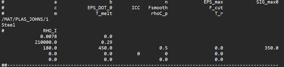
- we can also open "FIRST_RUN_0000.rad " starter file in notepad and find the Material properties, as highlighted in the image below
- Speed of sound in the material (v) = √E/ρ.
- where E = Young's modulus
- ρ">ρ� = density .
- Speed of sound (v) = √210000/0.0078 = 5188.745 m/s.
2.The length of the rail is about 1000 mm calculate the time takes for a shock wave to travel from one end of the rail to the other.
- Shock wave travels at the speed of sound.
- shock wave speed = speed of sound = 5188.745 m/s.
- time=distance/speed ofwave
- time takes for a shock wave to travel from one end of the rail to the other = 1000/5188.745 = 0.192724 ms.
3.Time for sound to travel length of rail= 0.1927 ms.
4. Edit the engine file so that the stress wave can be monitored, moving from one end of the rail to the other during an impact -this will require a termination time equal to the time it takes for the sound to travel the length of the rail(set on/RUN card).
- We have to give the end time to be 0.1927 ms. There are two methods to do it.
- First is just open the "0001.rad" engine file in Notepad and edit the end time value in the file..
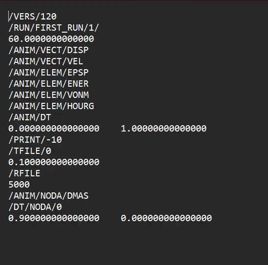
- Engine File after editing the required values we calculated.
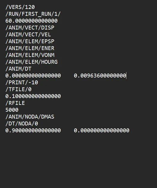
In hypermesh ,In the second method, we change the value in the hypermesh itself. There we go to the ENG_RUN card. There we change the Tstop value. There we have to give the value to be 0.1927 and after that, we have to run the file. So it will change the values in the 0001.rad file itself.
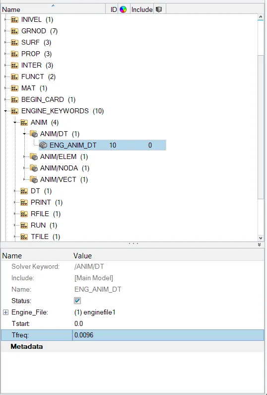
5. Set the frequency of animation output to a time that will give 20 animation steps(/ANIM/DT).
- Frequency = time/no. of revolution.
- 0.1927/20 = 0.009636.
- So to change this value. We have two methods
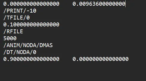
- First is just open the 0001.rad file and edit the end time value in the file
- In the second method, we change the value in the hypermesh itself. There we go to the ENG_ANIM_DT card. There we change the Tfreq value. There we have to give the value to be 0.009636 and after that, we have to run the file. So it will change the values in the 0001.rad file itself.
- Using hyper crash
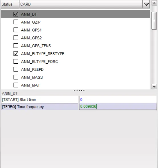
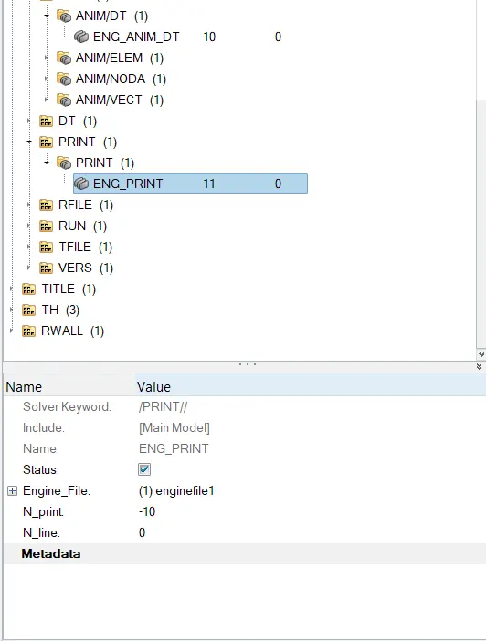
Change /print -10.
Using hyper crash
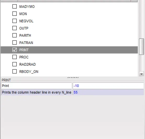
Using hypermesh radioss.
- We can see that the by default PRINT value is 10. So there is no need to change that
3D meshing:
Methods to generate Tetra Meshing:
There are three methods to generate Tetra Meshing as stated below
- Conversion of 2D tria to Tetrahedral Elements, by using Tetra Mesh panel.
-
Using the Quick Tetra Mesh, from the Utility panel.
-
Using the Volume Tetra Mesh panel.
1. Conversion of 2D tria to Tetrahedral Elements, by using Tetra Mesh panel.
-
Import the Model into HyperMesh and clean the geometry.
-
Delete the solid from the model, by selecting the Delete→ Solid→ Delete entity.
-
Now perform the 2D meshing on the model, by selecting the Mesh type as “Trias”.
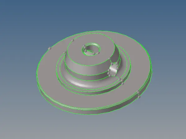
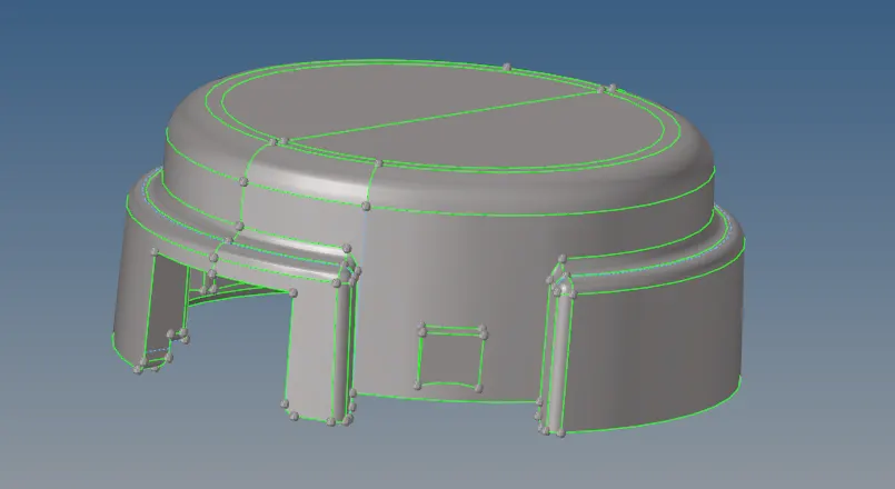
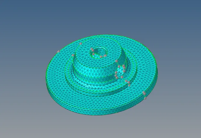
- After completing the 2D meshing, the model should be cleared with the Minimum and Maximum Elemental error.
- Now the model is ready to perform the Tetra Meshing. Select the 3D→ tetramesh option.
- In the tetra mesh panel, select the elements under the “Fixed trias/quads to tetra mesh” option .
-
After selecting the elements, click on the “Mesh” button
Hexa Meshing
MESHING OF ARM BRACKET USING BRICK ELEMENTS
Obejective:
- To import the arm bracket model.
- To clear the geometrical error, if any present.
- To mesh the bracket using brick/hex elements.
Procedure:
- The meshing of any component using Hexa elements is complicated as compared to the mesh using tetra elements.
- Generally, tetra mesh is widely preferred when the stresses generating on the component are not the part of concern and vice versa.
- In this assignment, the arm bracket has to be meshed using only brick elements.
- To do that, different methods had to follow for different sections of the arm bracket.
- Firstly, the arm bracket model was imported into the software.
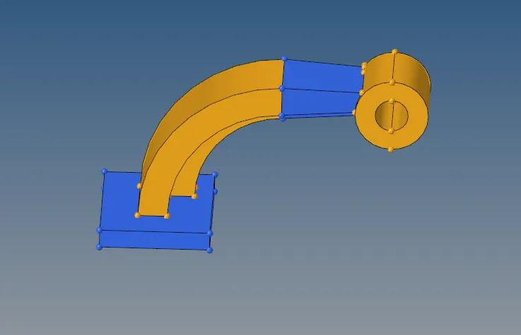
- From the figure, it can be observed that the arm bracket model consists of four different sections.
- While meshing using Hexa elements, manual inspection is required for nodal connectivity.
- Thus, each section had meshed individually.
- Firstly, the face of section 1 is meshed with 2d elements of size 5 units.
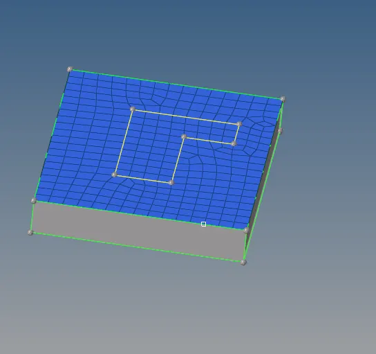
- Now, using 3D → elem offset → solid layers, the 2d shell mesh is converted to 3d Hexa mesh with element thickness of 5 units and 5 layers,.
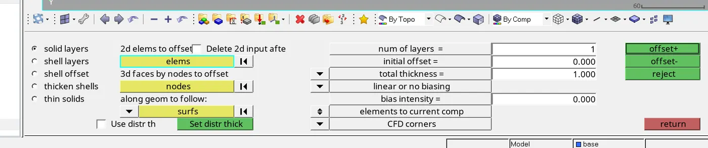
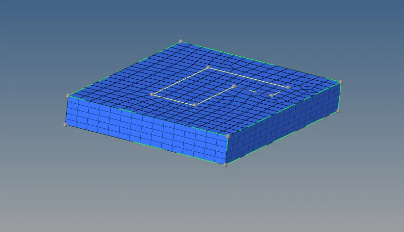
- After the meshing of section 1, for the meshing of section 2, the different methods had to follow because of its curved shape,
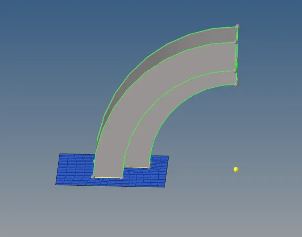
- To mesh section 2, firstly, a center of the curve is obtained for reference. It can be obtained using Geom → nodes → Arc Center, or Geom → distance → three nodes. After taking out the center, using 3D → spin → spin elems, the shell mesh inscribed by the curve is selected and it is spin about the center for 90º with 25 layers of elements .


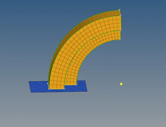
- he spinning of shell m along the x-axis for 90º to create 3d Hexa mesh on the curved section.
- Once section 2 is ready with 3d Hexa mesh, for meshing of section 3, which is a tapered section as shown in fig. 6, the shell mesh of section 2 is required.
- Using find faces we have to get the arm curve faces to mesh the section 3.


- To get the shell mesh of section 2, Tool → faces → elems is used. It appears exactly like 3d Hexa mesh of section 2,
- But when some of its elements are masked, it is hollow from inside.
- Now, to mesh section 3, the rows and columns of shell elements available on one side of it, the other side has to mesh with the same number of rows and columns using shell elements.
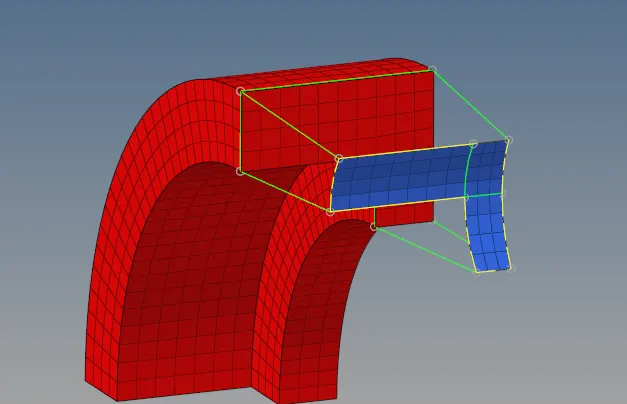
- he second side of section 3 is meshed with the same number of rows and columns as present on the first side.
- Now, using 3D → solid map → general, selecting the elements to drag and elements to match, and providing the element size of 5 units along the lines as can be seen in fig. 7, section 3 has meshed with Hexa elements.
- To mesh section 4 or boss section, the section was divided into multiple sections
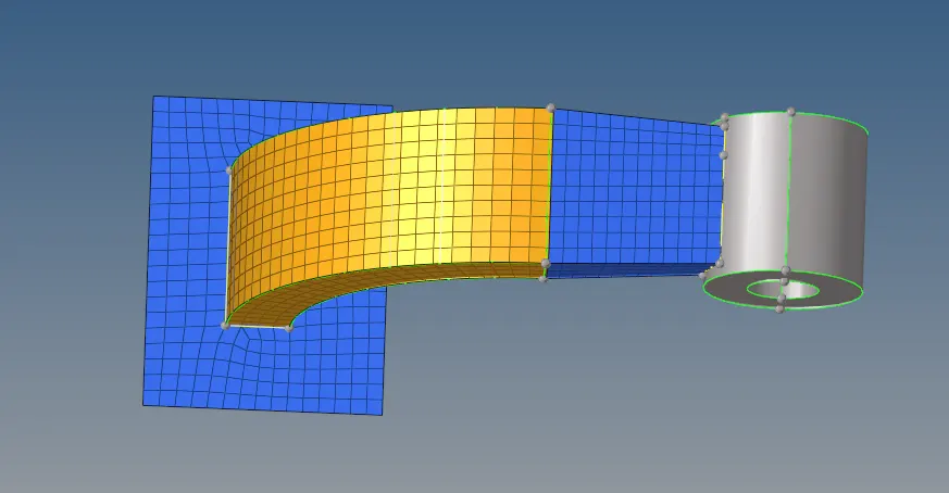
- Using 3D → solid map → line drag, providing the shell elements of the boss as source elements, and node path as a reference, the boss was meshed,
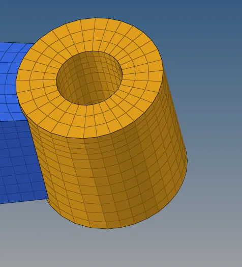
- The boss of arm bracket model meshed with 3d Hexa elements.
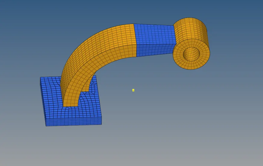
- This is how all the sections of the arm bracket model mesh and the completely meshed model appear