Assignment 2-RADIOSS Engine File Editing & 3D Meshing Challenge
1) Engine File
Import the ‘FIRST_RUN_000.rad’ file to hyper mesh solver, to read the data related to the file.
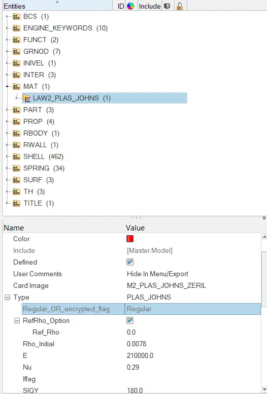
Read the material protective of the component.
The time step and the animation time frequency are calculated using the following steps.
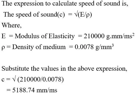
Thus, the expression to calculate the velocity of the sound is 5188.74 mm/ms.
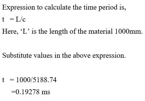
Thus, the time required for the sound to travel through the material is 0.19278 ms.
The expression to calculate the time for 20 frequency is,
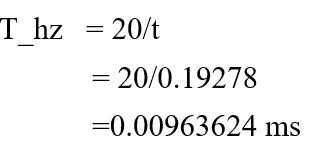
Thus, the time interval to capture the animation is 0.00963624 ms.
2) Housing
Import The model to the hyper works.
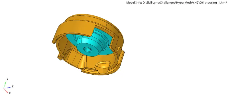
Use automesh(2D) system to mesh the surface of the body
This 2D mesh can be converted to the 3D mesh by using the tab feature ‘tetramesh’.
During the mesh study process, only the ‘trias’ is considered for a better understanding of mesh and quality.
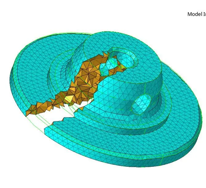
After meshing the ‘hub’ the element quality is checked.
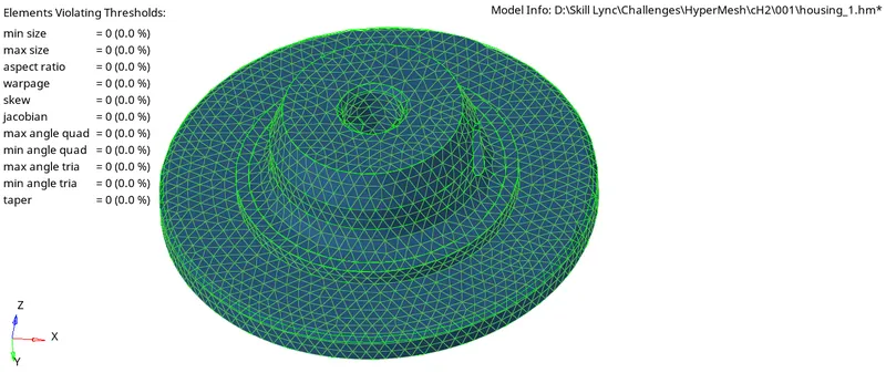
Now the ‘cover’ is directly converted to 3D mesh with the help of volume tetra mesh or ‘Quick TeraMesh’
(View > Browser> HyperMesh > Utility > Geom/Mesh > Quick TetraMesh).
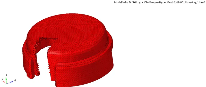
Once The mesh is Created check the quality of the elements.
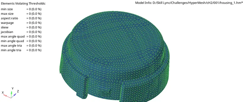
Final Mesh Form
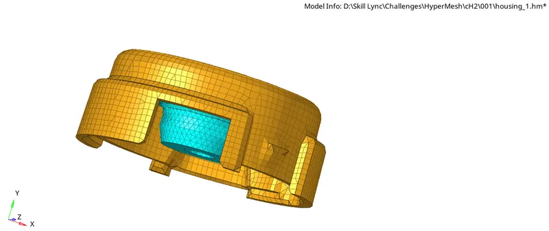
3) Arm Bracket
Import The model to the Hyper works workspace.
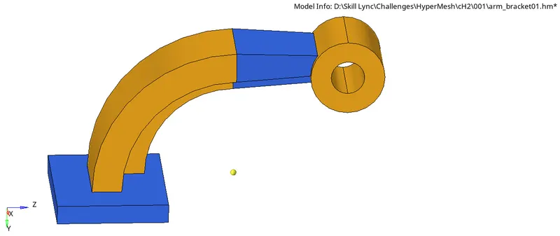
The base part is meshed using the automesh (2D). Once the 2D mesh is formed offset the element along the surface or drag the elements along the line. Once the 3D elements are formed the 2D elements have to be deleted.
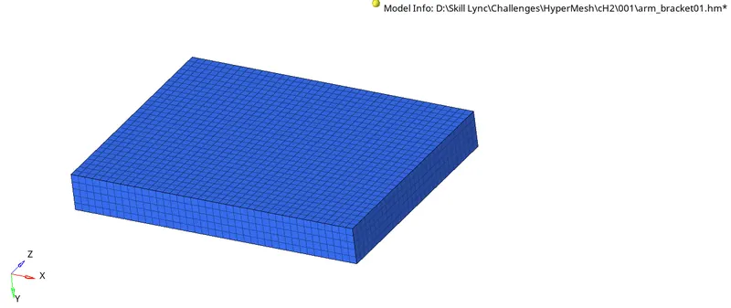

Some elements on the base are selected to mesh the ‘Arm Curve’. To mesh the arm curve the ‘spin’ feature under the 3D mesh tab is used. For proceeding with the spin feature the model needs a center point or nod and a spin axis.
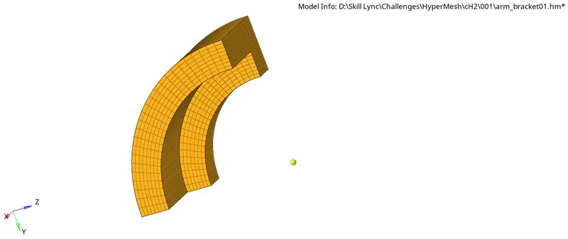

The Arm straight is meshed using the ‘linear Solid’ feature. For this feature to work we need a start and end element phase with the same number of elements in respective directions. The start elements are copied from the ‘arm curve’ using the ‘faces’ feature, and the end elements are made using the 2D ‘Automesh’ feature on a surface.
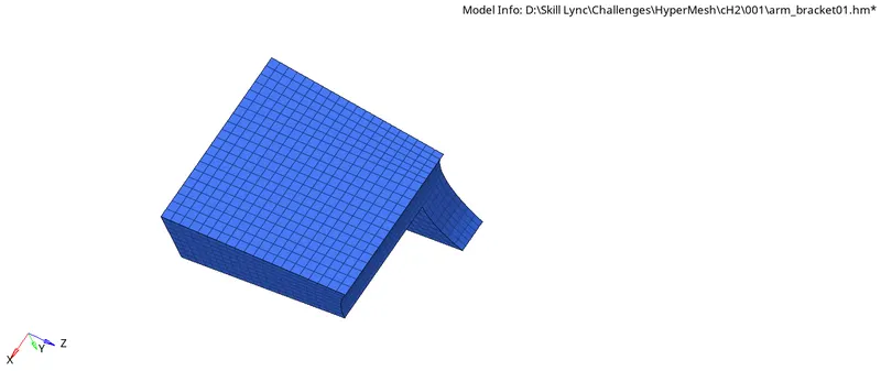

The boss feature is meshed using the ‘Solid Map’ feature. For that one of the flat faces is selected and meshed using the ‘Automesh’ feature. And the 2D meshed are mapped along the nodes on the ‘arm straight. We can also use a line on the curve surface.
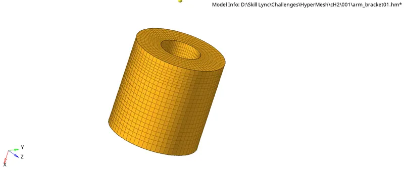

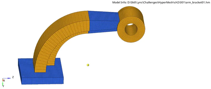
Final Model (Mesh)