Assignment 2-RADIOSS Engine File Editing & 3D Meshing Challenge
Aim:- To study about starter file and engine file in RADIOSS by changing the parameters for the given file.A And perform 3D meshing ( Tetra and Hexa meshing ) on the given components.
Objective:-
* Check the material properties of the given rail component and give the answer of questions.
* Edit the engine file according to given instructions.
* Perform 3D meshing on given components with given element size and maintain quality.
Questions and Answer:-
1. Check the material properties of the rail component and calculate the speed of sound in steel rail=_______
* First we have to check the material properties of rail components.
* For this we import the given starter file in Hypermesh.
* We have '.red' file , so for that we have to set RADIOSS user interface.
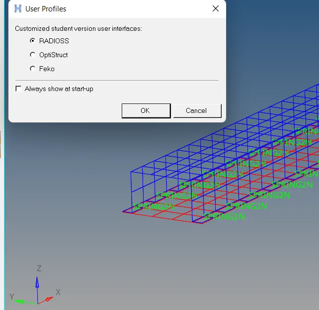
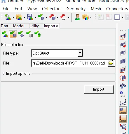
* Now we will go to the import option. There we are going to select the 0000.rad file and import it.
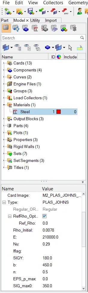
* After importing file we will go to material property and check the values. we can see the density and Young's Modulus of steel under Material property in Model browser window.
* we can also open "FIRST_RUN_0000.rad " starter file in notepad and find the Material properties.
* Calculation-
* Speed of sound in the material (c) = c= √(E/ρ)
* where E = Young's modulus
* ρ = density
* So speed of sound (c) = √(210000/0.0078) = 5188.745 m/s
2. The length of the rail is about 1000 mm.calculate the time takes for a shock wave to travel from one end of the rail to the other.
* The length of the rail=1000mm
* shock wave speed = speed of sound = 5188.745 m/s
* time = distance / speed of shock wave
dt = l/c
* time takes for a shock wave to travel from one end of the rail to the other = 1000/5188.745 = 0.1927 ms
3. Time for sound to travel length of rail= 0.1927ms
4.Edit the engine file so that the stress wave can be monitored, moving from one end of the rail to the other during impact -this will require a termination time equal to the time it takes for the sound to travel the length of the rail(set on/RUN card)
* We have to give the end time to be 0.1927 ms.
* For editing the file we open this file in Notepad and edit the end time value in the file.
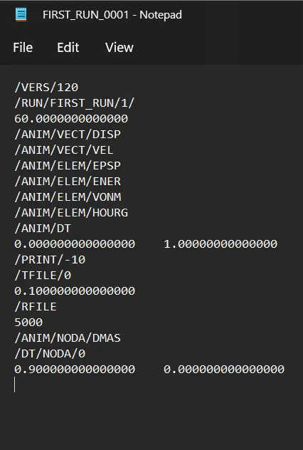
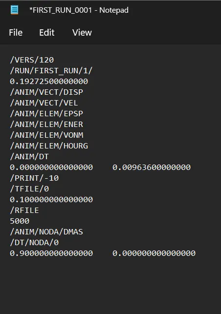
5.Set the frequency of animation output to a time that will give 20 animation steps(/ANIM/DT)
* frequency =Termination time/Number of animation steps.
* Termination time = 0.1927248223318ms. and animation steps=20
* Animation frequency = 0.009636
* Change value of animation frequency
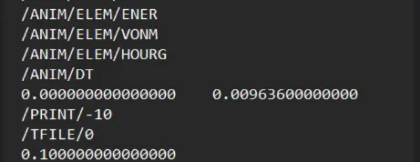
6.Change /print -10.
7.3d meshing tetra mesh and hex mesh
- Repeat class examples and, maintain the quality.
- Target tet size=5mm,hex size=10mm,tet collapse=0.15.
3D Tetra Meshing:
For Housing Model:-
* For this model we use, Conversion of 2D tria to Tetrahedral Elements, by using Tetra Mesh panel.
1. Import the model and clean the geometry:-
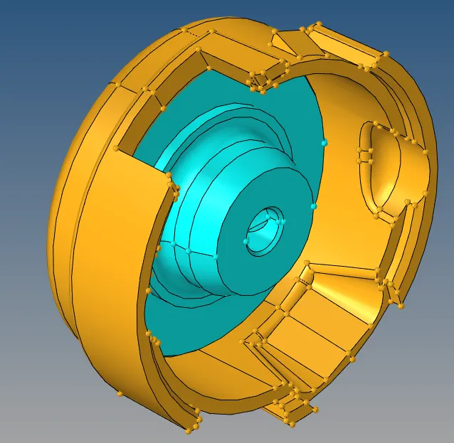
* Import the housing model.
* This model contain 2 components.
2. Geometry cleanup and defeaturing:
* We will check model for any free surfaces, gaps , overlaping surfaces by viewing in visualization panel.
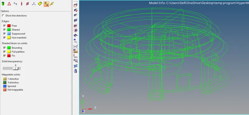
In the given model there is no free surface , gap and overlaping surfaces, hence we can proceed with geometry cleanup in which we remove the lines by toggling where minimum thickness occur.
3. 2D Meshing:
* As per the method ( 2D to 3D trtra meshing ) we have to first create 2D mesh with tria element.
* For 2D meshing we use automesh tool then we select the surface and meshing done. (2D - automesh - sixze and bias -select surface)
* Before meshing we set the quality criteria for 2d elements. ( min length = 3 , max = 7 , target = 5 )
* For 2D meshing we use only tria element because our aim is to do 3D tetrahedral meshing on given components.
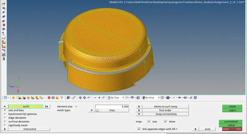
* After meshing we check element for quality, as we observed many element are failing for min and maximum size so to resolve that we use remesh tool and also use quality index panel for rid of this problems.
* At the end we check all elements are passed our quality criteria for obtain required 3D tetrahedral meshing.
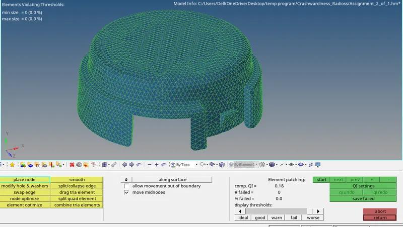
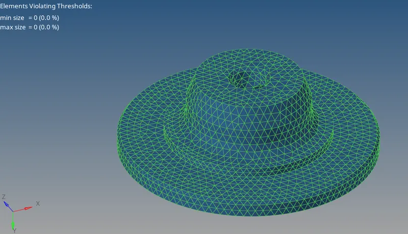
* We do all above processes individually for both components.
4. Tetrameshing ( Converting 2D to 3D mesh )
* As per method we have to generate 2D mesh into 3D mesh. in order to do this we go to 3D panel and then tetra mesh , select the 2D elements and click on mesh. (3d - tetra mesh - tetra mesh - element)
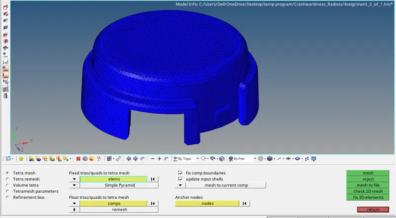
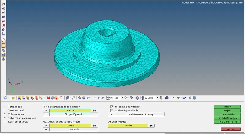
* We done 3D meshing individually for both component.
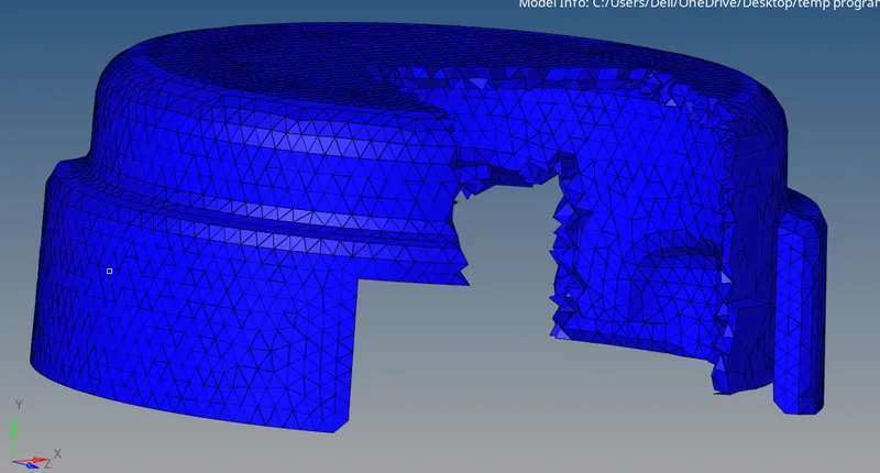
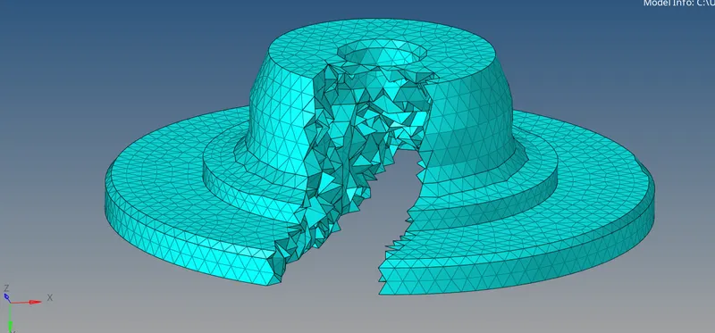
* Above image shows representation of 3D mesh.
5. Element Qualily checkup :
* Ones the tetra mesh is created we will check for quality of 3D elements.
* For quality check we use check element tool in which we only check for Tet collapse because the given quality requirement is only tet collapse. ( Tool - check element - 3-D - Tet collapse )
* We check elements for tet collapse with the value of 0.15 as per given guidline.
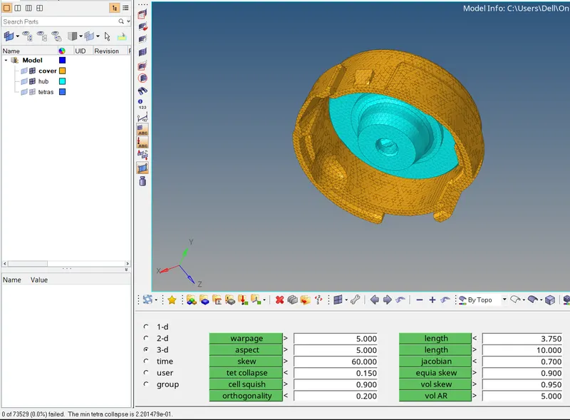
* As we clear the quality issue of 2D elements there was no Tet collapse issue in the 3D mesh as above figure shows.
3D Hexa Meshing:
For Arm Bracket Model:-
Procedure:-
* Importing the model.
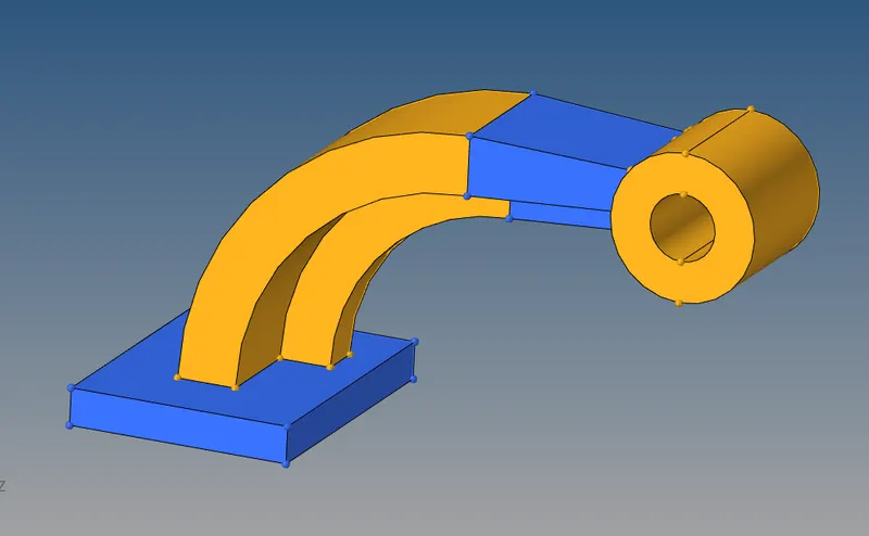
* From the figure, it can be observed that the arm bracket model consists of four different sections. While meshing using Hexa elements, manual inspection is required for nodal connectivity. Thus, each section had meshed individually. Firstly, the face of base part is meshed with 2d elements of size 10 units, as shown in fig.
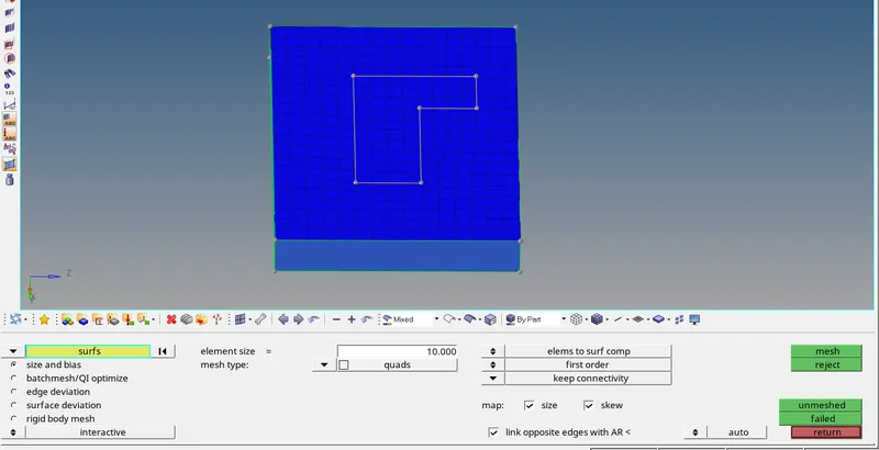
* Now we have to do 3d meshing on base so that we use element offset tool which create 3D element by offseting the 2D elements.( 3D - ele offset - solid layers )
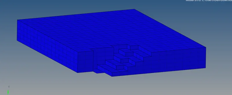
* After the meshing of Base part, for the meshing of Arc comonent, the different methods had to follow because of its curved shape.
* First we create arc centre by distance tool using 3 node option.
* Then we use spin elements tool for creating 3D mesh on this curved part. we give value of angle as 90' and layres value 25.
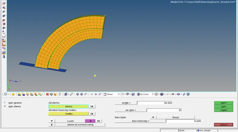
* The spinning of shell element along the x-axis for 90º to create 3d Hexa mesh on the curved section.
* After meshig this curved part we mesh the tapered section of middle arm.
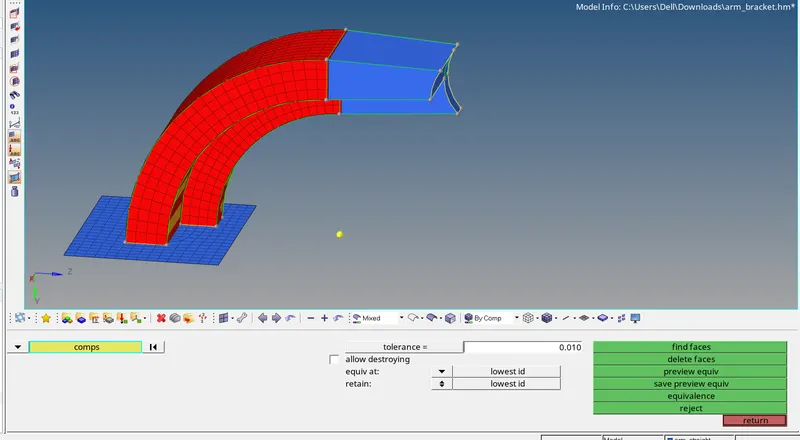
* For this first we create faces of 2D elements as shown in below image. ( tool - faces )
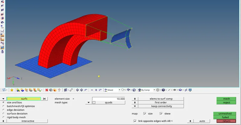
* Then we create shell mesh for other side. This surface mesh elements is same column and row as 2D faces elements
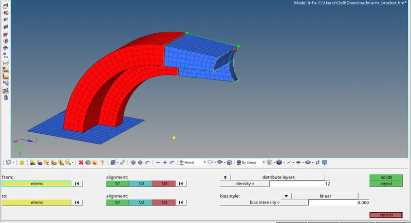
* Now, using 3D - solid map - general, selecting the elements to drag and elements to match, and providing the element size of 10 units along the lines as can be seen in below fig.
* After this part we go for meshing boss section.
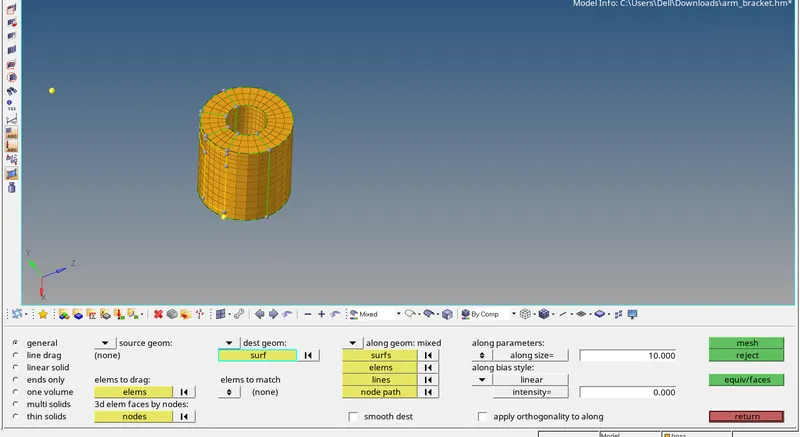
* For meshing this part first we mesh 1 side circular surface with 2D elements.
* Using 3D → solid map → general, providing the shell elements of the boss as source elements, and node path as a reference, the boss was meshed, as shown in below fig.
* In this way we mesh the arm bracket mdoel with 2d elements.
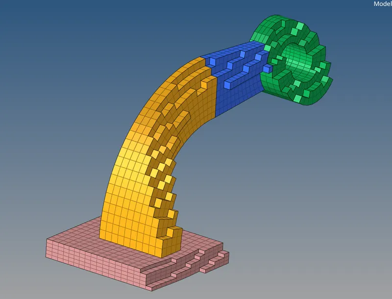
Fig - Representation of 3D mesh.
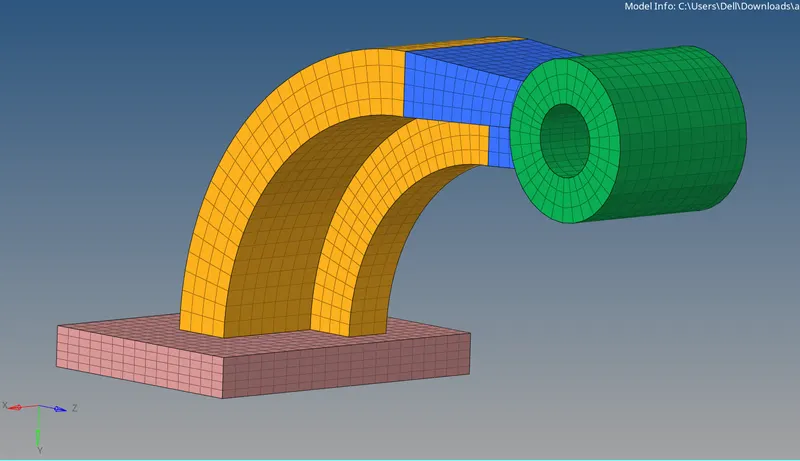
Fig - Complete meshed model.
Result:- The given engine file is edited as per given instructions and requirements and also 3D meshing is successfully done on given components as per instructions.
Conclusion:-
Here we successfully edited the RADIOSS engine file and done 3d meshing on the given components as per given requirements.