Assignment 2-RADIOSS Engine File Editing & 3D Meshing Challenge
Assignment 2-RADIOSS Engine File Editing & 3D Meshing Challenge
Objective:
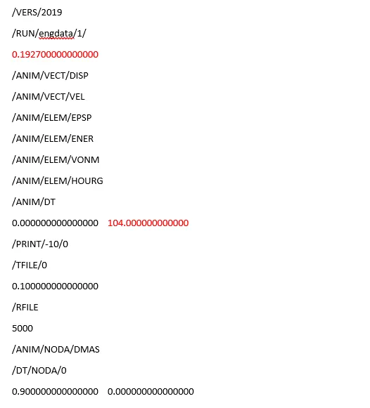
Engine File Snippet:
Questions:
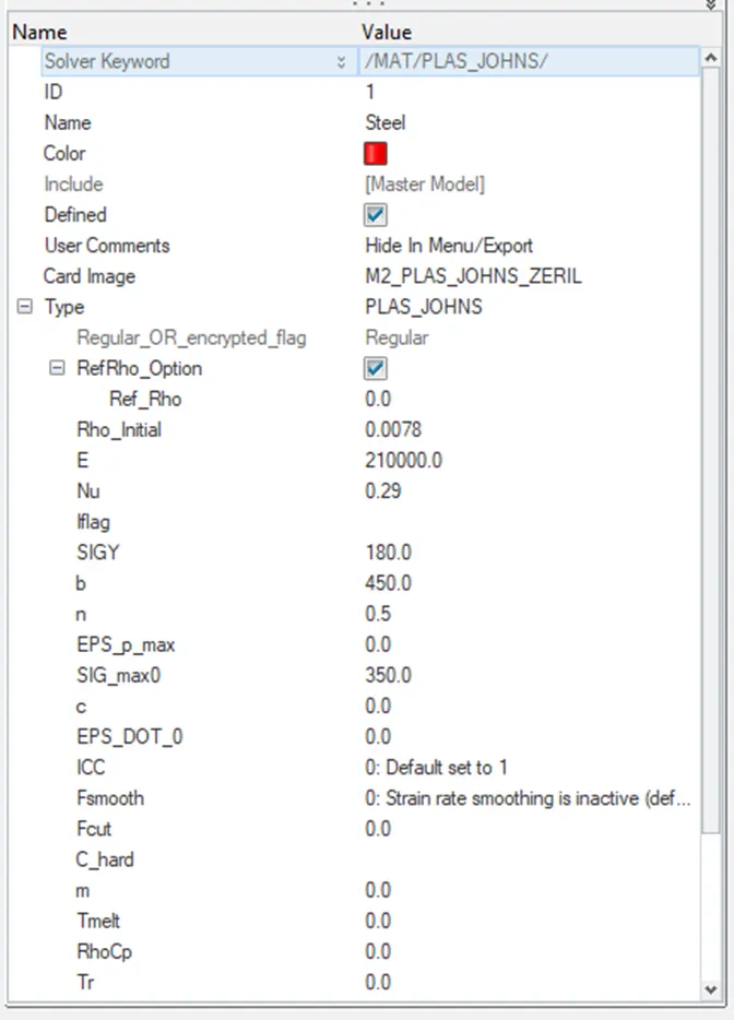
1. Check the material properties of the rail component and calculate the speed of sound in steel rail=_______
2. The length of the rail is about 1000 mm.calculate the time takes for a shock wave to travel from one end of the rail to the other.
3.Time for sound to travel length of rail=______
4.Edit the engine file so that the stress wave can be monitored, moving from one end of the rail to the other during impact -this will require a termination time equal to the time it takes for the sound to travel the length of the rail(set on/RUN card)
5.Set the frequency of animation output to a time that will give 20 animation steps(/ANIM/DT)
6.Change /print -10.
7.3d meshing tetra mesh and hex mesh
- Repeat class examples and, maintain the quality.
- Target tet size=5mm,hex size=10mm,tet collapse=0.15.
Solution:
Calculation of speed of sound in the rail component
Speed of sound in any steel, c = √E/ρ
C = √210000/0.0078 = 0.5188 × 10 4 m/s = 5188.75 m/s
The length of the rail is about 1000 mm
Distance = 1000 m
Time taken t= d/c = 1000/5177.75 = 0.1927 ms
Time for sound to travel length of rail for 1000mm rail
Time t = 0.1927ms
4,5,6
Termination time is nothing but the value of time taken 0.1927ms.
Therefor time frequency, Tfrequency = (0.192/20 )-1 = 103.788 ms, which is approximatly = 104 ms
7. .For 3-D meshing of given models given that,
Target tetra size=5mm
Target hex size=10mm
Target tet collapse=0.15.
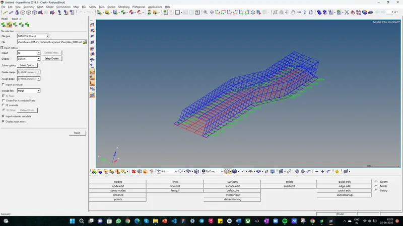
Models given are,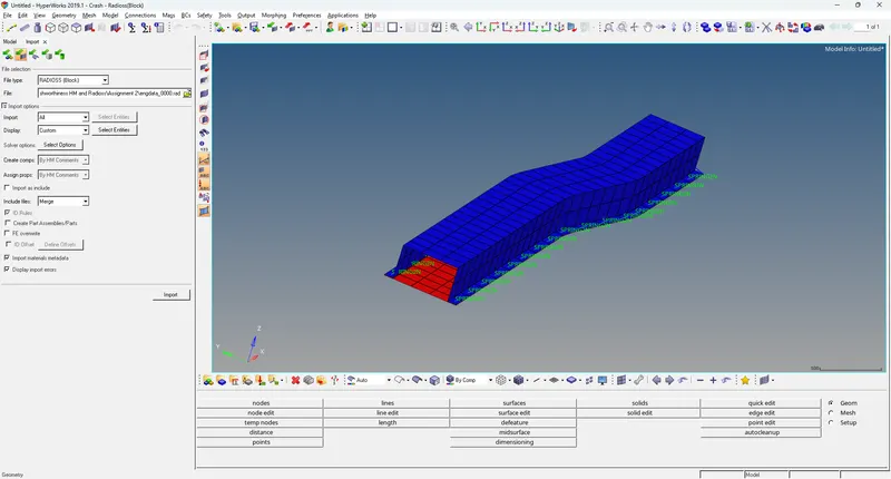
3d meshing tetra mesh and hex mesh
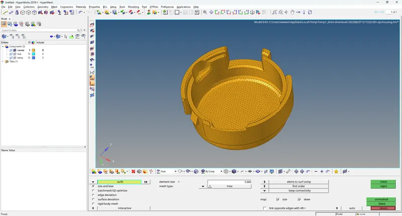
1. Housing Model (Tetramesh) – The given model is as follows,
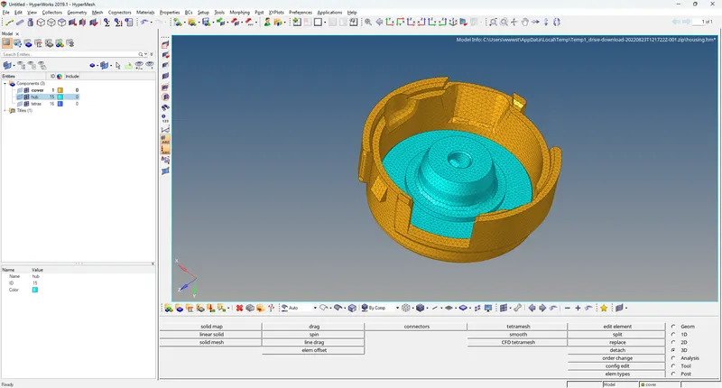
We will inspect the model for surface flaws after loading it into Hypermesh so that we can perform geometry cleanup. We will move forward with meshing because the model has no surface flaws. The model consists of two parts: the hub and the lid. So, one by one, we will mesh them. As listed below, there are three general ways to create tetra meshes:
- Using a Tetra Mesh panel, convert 2D tria into tetrahedral elements.
- utilising the Utility panel's Quick Tetra Mesh.
- Volume Tetramesh panel usage.
As a result, we will mesh the hub component using the first technique, which involves transforming 2D tria to 3D tetra components. We will set the hub component as our current component, hide all other components, and then use the F12 keyboard shortcut to access the 2D Automesh panel. Here, we'll choose the surfaces that are visible and type the value 5 mm for the target element size. The most crucial step is to click on mesh while selecting the mesh type as trais alone. We must transform the hub's 2D tria elements into 3D tetra elements after they have been created. To do this, we will navigate to the 3D page's tetramesh panel and choose the Fixed trias/quads to tetra mesh option before selecting the 2D tria elements. The following is

2. Arm Bracket (Hexamesh) – The given model is as follows
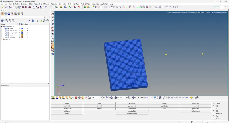
We will inspect the model for surface flaws after loading it into Hypermesh so that we can perform geometry cleanup. We will move forward with meshing because the model has no surface flaws. The model consists of four parts: base, arm curve, arm straight, and boss. So, one by one, we will mesh them. We will mesh the base component first because meshing the other three components later on can be helpful. Making it our current component will allow us to conceal all other components. On the top surface of the base component, we will create a 2D mesh by choosing the mixed mesh type. Therefore, we will basically build every 2D quad element on the surface.We will offset these components in order to transform them into 3D hexa elements. So, we'll head to the element offset panel on the 3D page. Here, we will choose the 2D items to offset under the solid layers panel, specify the number of layers as 5, the total thickness, which is 25 and then click on the offset command. By offsetting the 2D elements in 5 layers to a thickness of 25, this will produce 3D hexa elements.
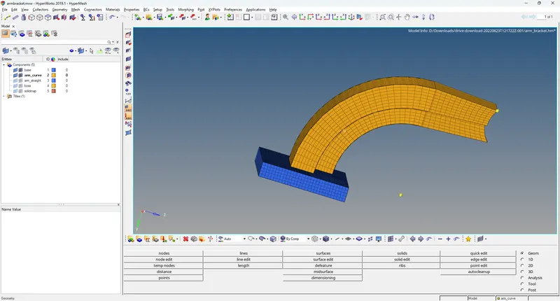
We will now mesh the arm curve component that connects the base because the base component has the imprint topology of the arm curve component. We'll make it the active component and conceal the others. This component's geometry is shaped much like a partial torus. Therefore, we can rotate the components to create a 3D hexa mesh. We will then navigate to the spin panel on the 3D page. In the spin elems sub-panel, we'll choose the 2D elements from the imprint area, input 90 for the angle, 25 for the spin, and choose the x-axis as our rotation axis. The F4 shortcut key will be used to access the distance panel from the base point, and the three nodes option will be used to build a centre node. the central node.We'll utilise this centre node as the starting point and spin the elements using the spin option. As a result, 25 layers will be used to generate the 3D hexa components along the geometric profile.
We will now mesh the part that connects the arm curve with the arm straight. We will use the linear solid command to create a 3D mesh as this component has tapered geometry. To make a linear solid, we will require elements or faces in 2D. Therefore, using the 3D hexa components of the arm curve component, we will make faces. We will choose the components of arm curve in the faces panel on the Tool page, then click locate faces. The arm curve elements will get faces as a result of this. We will generate a 2D mesh on the opposing tapering surface of the arm straight component so that the nodes and elements perfectly match the opposite face, as illustrated below.
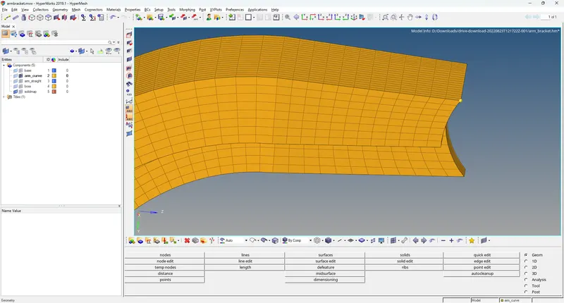
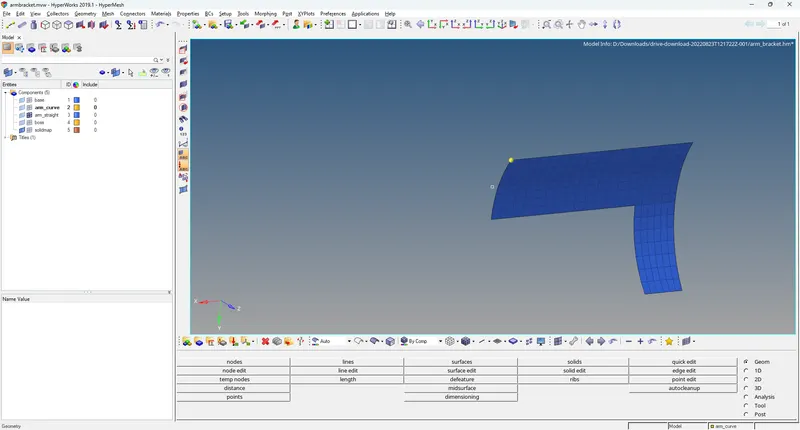
Next, we'll go on to the 3D page's linear solid panel. Here, we'll choose between elements as the components' faces, which are shown on their joining surfaces in red, and elements as their tapering surfaces, shown in blue. We will adjust the density to 12 and then click on solids to ensure that the nodes are properly aligned. By doing this, 12 layers of solid hexa elements will be created, linking the two meshes. We will now remove the earlier-created faces to obtain the following final result:
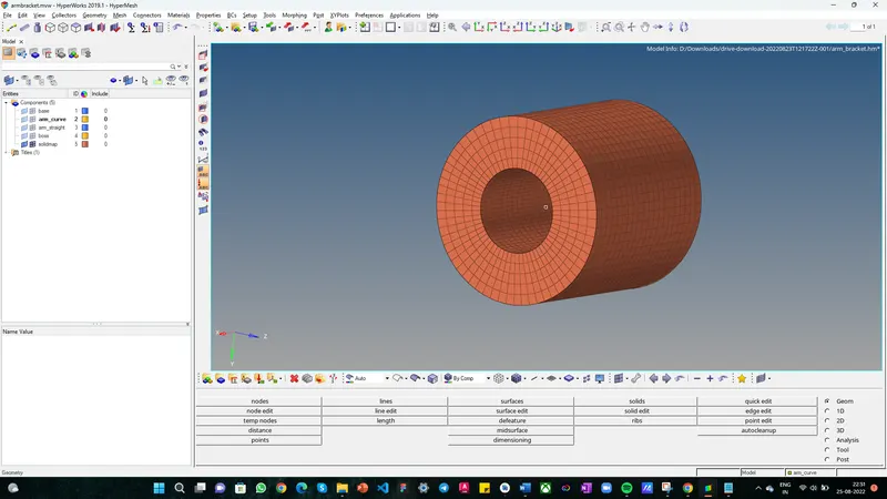
On the Boss component, meshing will now be done. We can mesh this component using a general solid map because we also need to connect the mesh to the components of the arm straight component. Using the project command, we will first project an outermost node to one of the component's plane surfaces. On the adjacent flat surface, a 2D mesh will then be created. Next, we'll go to the general sub-panel of the 3D page's solid map panel. The components to drag here will be the 2D produced elements, along geom will be the node route, and mesh will be selected after setting the source geom to none and the dest geom to be the opposite surface. By doing this, 3D hexa elements linking the components of the arm straight component will be created. These parts will be kept in a brand-new solidmap component. Using the organise command, we will move these components to the boss component. The mesh is thus as follows:
All of the model's 2D shell components will be removed in the end. We'll use the F2 shortcut key to go to the delete panel to accomplish this. Here, we'll click on the shown choose entities to select elements using the configuration quad4. This will choose every component of the 2D quad. Then, we can select the option to delete entities to remove all of the 2D quads from our model and replace them with 3D hexas.
Final Result –
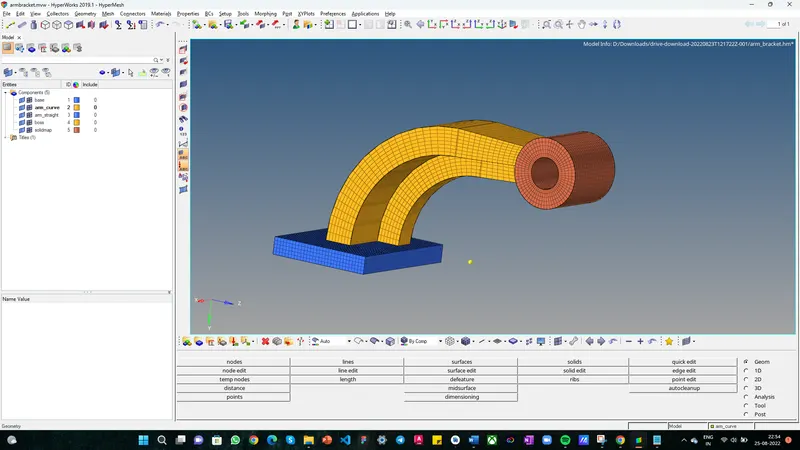
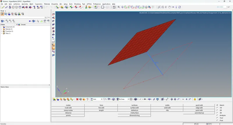
Line mesh
CONCLUSION :
It has been successfully calculated how fast sound travels through steel and how long it takes for a sound wave to travel the entire length of a steel rail. By directly altering the.rad file, these calculated values are provided as the termination time and the frequency of the animation output in the engine input file. Then, using the 3D solid elements (tetra and hexa) with the necessary quality and mesh flow, the two components (housing and arm bracket) are joined together.