Assignment 2-RADIOSS Engine File Editing & 3D Meshing Challenge
Aim: To calculating the values & editing values on the engine files, also to perform the volumetric meshing on different geometries by using hypermesh.
OBJECTIVE:
- To calculate the speed of sound in steel rail and also calculate the time taken by shock wave to travel in steel rail.
- To edit the engine file for termination time and animation time step.
- To perform shell mesh on housing component and also have to fix the quality issues.
- To perform volumetric meshing with tetrahedral elements for housing component and fixing Tet-collapse issues.
- To perform volumetric meshing with hexahedral elements for arm bracket.
PROCEDURE:
1. Check the material properties of the rail component and calculate the speed of sound in steel rail.
To check the material properties of rail component, we have to open the .rad file. So, to open the required “FIRST_RUN_0000.rad” file we have to follow:
File--->Import---->Solver Deck---->File: select file--->Import.
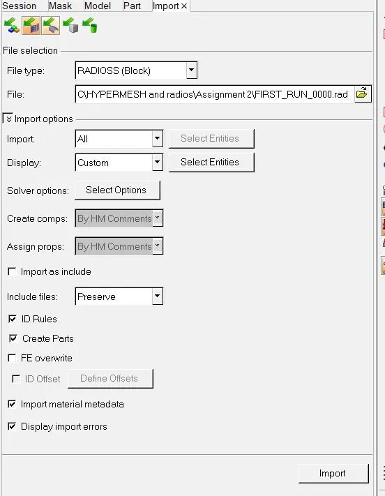
Once file is opened, it will look like as shown in picture below.
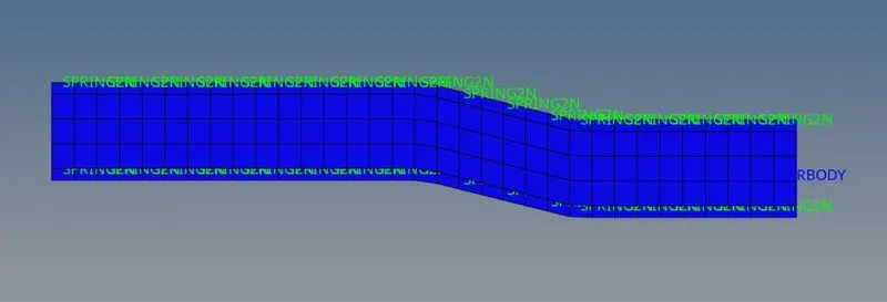
Now, in order to check the material properties, we have to follow:
Model--->Materials---->Steel---->refer below image.
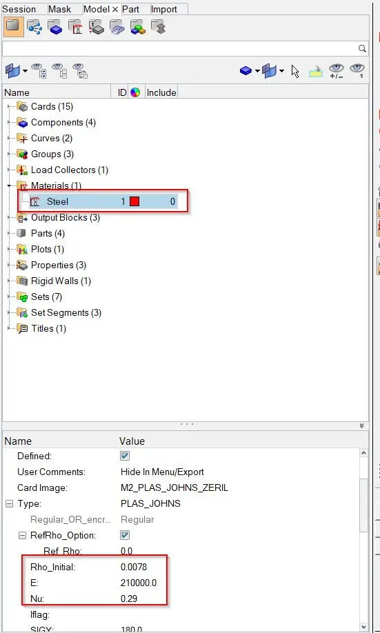 |
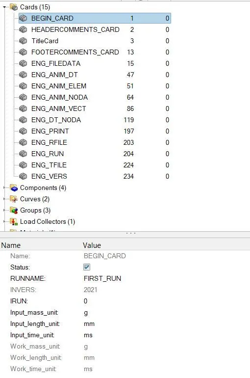 |
From above picture we can see the material properties, such as
Density (Rho) = 0.0078 g/mm3
Young’s modulus(E) = 210000 N/mm2
Poissons ratio(Nu) = 0.29
Speed of sound in steel rail, c = √(E⁄p)`
where, c denotes speed of light.
E denotes Young’s modulus.
Rho is density.
c = `√(210000⁄0.0078)`
c = 5188.7452 mm/ms
2. The length of the rail is about 1000 mm. Calculate the time takes for a shock wave to travel from one end of the rail to the other.
Length of rail = 1000 mm
Time for sound to travel length of rail, Ts = `(Length of rail)/(Speed of sound in air)`
Ts = `1000/5188.74`
Ts = 0.1927ms
3. Time for sound to travel length of rail
Time for sound to travel length of rail = 0.1927ms
Time for a shock wave to travel from one end of the rail to the other end is equal to the time for sound to travel over length of rail.
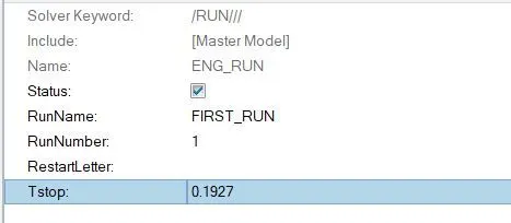
4. Termination time = Time for sound to travel length of rail = 0.1927ms
Now we have to update the termination time or Tstop time in model cards as shown in picture below.
Model ---->Cards---->ENG_RUN
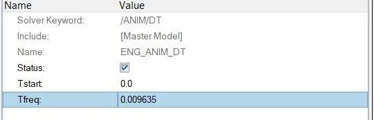
5. Set the frequency of animation output to a time that will give 20 animation steps(/ANIM/DT)
Tfreq = `(Termination time )/(animation steps)`
Tfreq = `(0.1927 )/20`
Tfreq = 0.009635
Now in order to edit the card we have to follow:
Model ---->Cards---->ENG_ANIM_DT
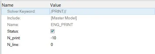
6. Change /print -10.
To edit the card we have to follow:
Model ---->Cards---->ENG_PRINT
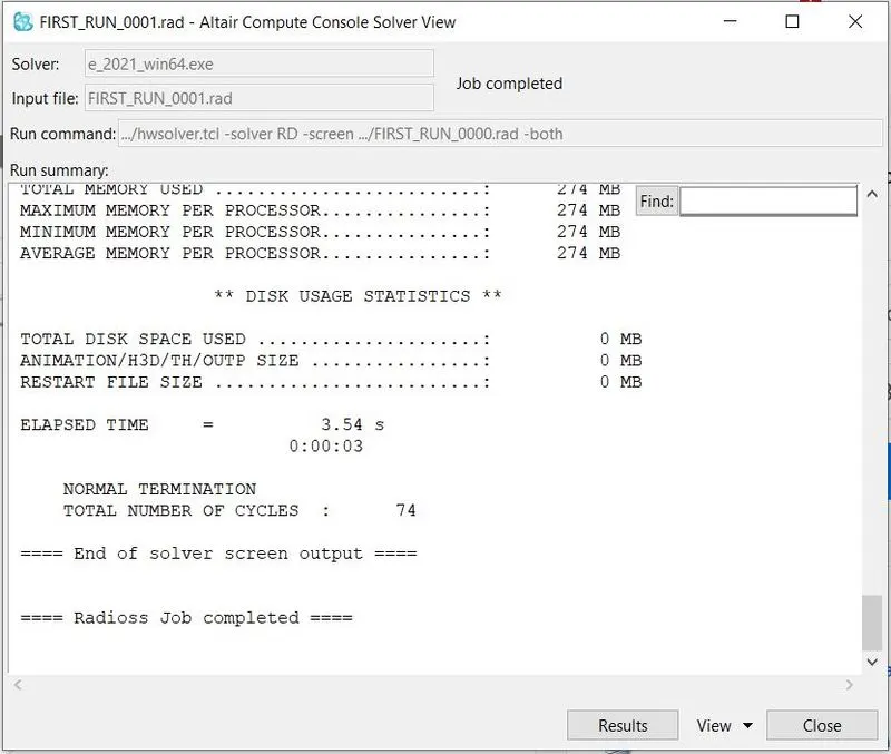
Now we can check the animation depending upon Tstop and Tfreq, by following:
Analysis---->Radioss
Now we have to give location to export the input file:

click on Radioss, and new window will get pop-up. A simulation will start to show result,
Now click on result and new window will get pop-up with result as shown below.
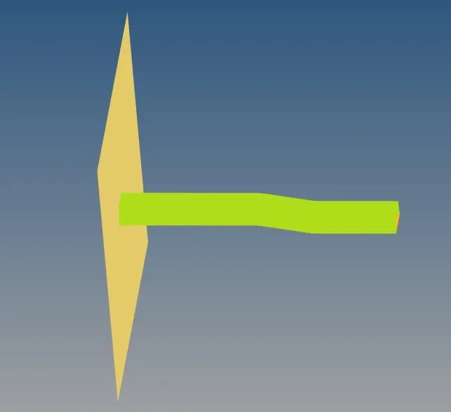
By using different animation controls, we can check and animate the results as shown in picture below.

Now we can check the number of animation frequency at file location of saved animations.
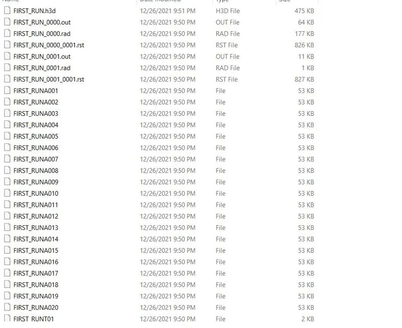
A. CAD MODEL 1-HOUSING:
1. Procedure:
Open the hyperworks software, and then we have to set user profile interface i.e. Optistruct or RADIOSS. Optistruct is implicit solver which handles small deformations. And RADIOSS is explicit solver which handles large deformation. So we will use RADIOSS as user interface.
First we have to import the required file, which is in .stp format. So to import the .stp file format model in hyperworks, we have to follow:
File--->Import---->Geometry---->File type: STEP---->select file--->Import.
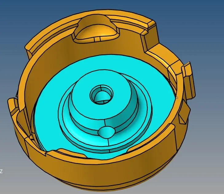
Figure 1: CAD model of Housing Component.
Once model is opened, then we will switch the geometry color mode from “auto mode” to “By Topo”. Once mode is changed model will look like as shown in picture below.
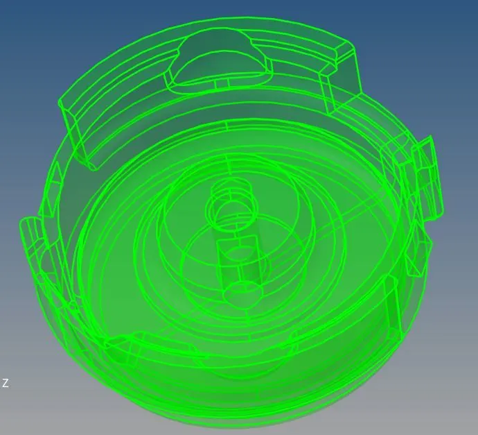
Figure 2: CAD model of Housing Component.
Once Housing model is selected to make it visible in hyperworks window. It will show the solid component. And we have need for surface only. From which we will extract mid surface. So, we have to delete the solid by using delete option. In order to use delete option. Under collectors select delete then select solid as displayed and then have to select delete entity. Once solid is deleted, we will only have surface. And the model will look like as shown in picture below.
By default, “auto mode” is selected in “geometry color mode”. If auto mode is on we cannot check the free edges, CONS, suppressed edges and sharp edges etc. which are the main criteria for geometry check.
Now we will switch the geometry color mode from “auto mode” to “By Topo”. Once mode is changed model will look like as shown in picture below.
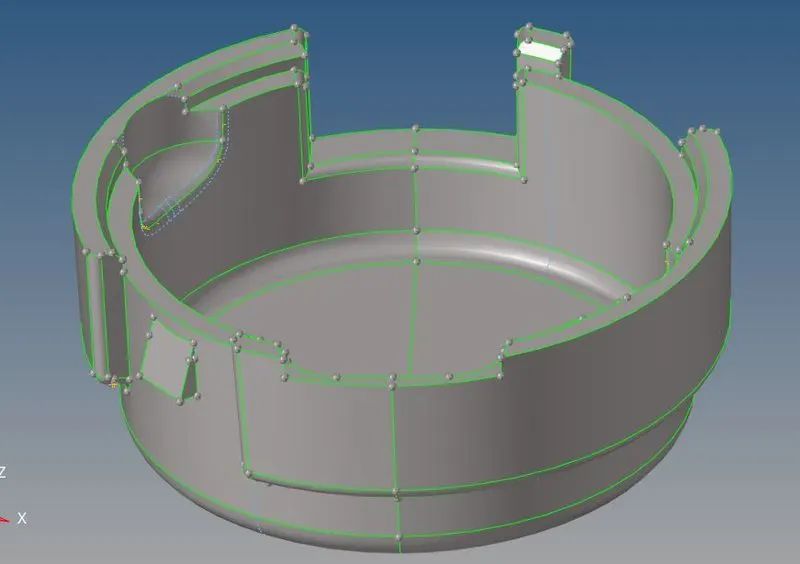 |
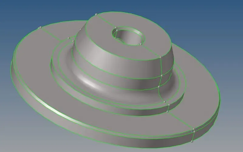 |
| Figure 3: CAD model of Housing Component. | Figure 4: CAD model of Housing Component. |
Free edges are shown in red color. In this surface edge is not connected to any other surface edge.
Shared edges are shown in green color. This is the boundary between two connected surfaces.
Suppressed edges are shown in blue color.
2. Geometry cleanup:
In ousing model we have edges dis-connectivity. Which means these edges have no shared edges and are acting like a free edge as shown in picture above.
In order to resolve these issues, we can perform toggle function under edge edit in geometry module by increasing the tolerance value. If this operation will not work, then we can perform either autocleanup and manually cleanup.
To perform geometry cleanup operation, we will use autocleanup panel. Cleanup operations include the equivalencing of "red" free edges, fixing of small surfaces (relative to the element size), and detection of features such as beads. It also performs specified surface editing/defeaturing operations like the removal of pinholes (less than specified size), removal of edge fillets, and the addition of a layer of washer elements around holes.
To perform this operation, we have to follow:
Geometry---->autocleanup---->select surface: all---->autocleanup
In order to resolve those errors which are not auto detected, we have to manually perform spline / filler, ruled options to repair geometrical errors by following
Geom---->Surfaces---->select spline/filler or ruled.
Spline/filler subpanel option helps to create surfaces by filling in gaps, such as a hole in existing surface. And ruled subpanel option helps to create surfaces by interpolating linearly between lines or nodes.
Once geometrical errors are resolved model will look like as shown in picture below.
As we will perform defeaturing, which will help us to provide good meshing flow by eliminating unnecessary CONS on flat surfaces. To suppress these unnecessary CONS we have to perform toggle function by following
Geom---->edge edit---->toggle.
3. Discretization of component:
A mesh is a network that is formed of cells and points. A meshing is the process of subdividing the structure from infinite number of points to the finite number of node and elements. This process is also known as discretization.
And we have to maintain the distance between two nodes equal to the average target length i.e. 5mm. This can be done by following certain steps i.e.
2D---->automesh---->select surface---->element size---->mesh type: trias---->mesh.
In order to fix quality meshing we will use some of useful function such as remesh, rebuild mesh, smooth, split elements, align nodes, replace nodes etc.
We will also use normal panel which is under tool. Normal panels help to display and reverse the normal of elements or surfaces.
Once discretization is done model will look like as shown in picture below:
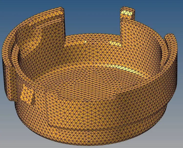
Figure 5: Discretization of Housing Component.
Now we need to verify the connectivity between the nodes throughout. To verify and correct connectivity we will use equivalence by following certain steps.
Tool---->edges---->select element---->preview equivalence---->equivalence
we can also increase the tolerance value if the nodes are not getting highlighted.
4. Result and Conclusion
4.1 Element quality checking
During meshing we have to take care of element quality. Element quality help us to understand how much the element has deviated from the ideal element. Because during meshing poor elements will misrepresent the geometry and will lead to inappropriate results. To perform quality check operation, we have to follow certain steps i.e.
2D---->quality index
In quality index we have cleanup tools which helps us to fix element quality such as drag tria elements, element optimize, split quad element and combine tria element etc.
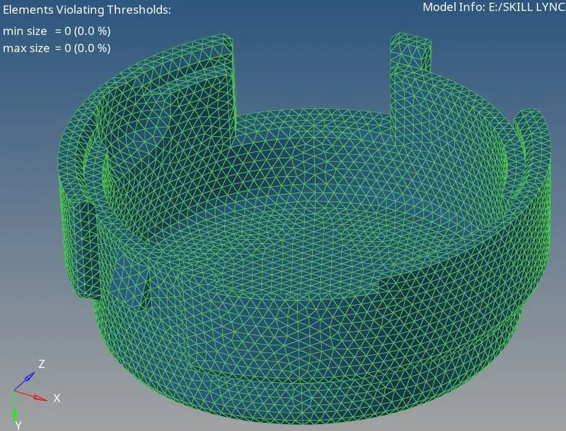
Figure 6: Element quality checking of Housing Component.
So from above mentioned picture, we can analyze practice model is passing quality criteria.
5. TO GENERATE TETRAHDRAL ELEMENTS USING SHELL ELEMENTS
To perform tetramesh on housing component, we will use algorithm type is Tetra mesh to generate meshing in interior of volume by following:
3D---->tetramesh---->Tetra mesh.
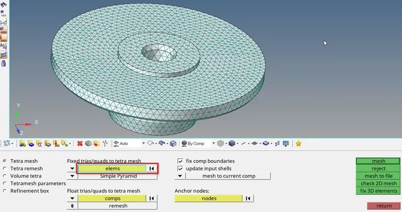
Figure 7: Volumetric meshinig of Housing Component.
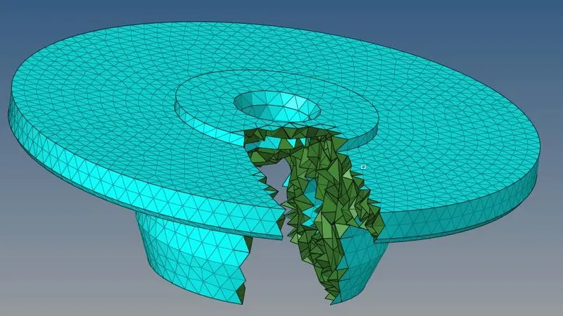
Also, for better mesh quality, we should have to fill Tetramesh parameters such as Max-Min tetra size, Tet collapse, smoothing etc. Once Tetra mesh is generated, model will look like as shown in picture below.
 |
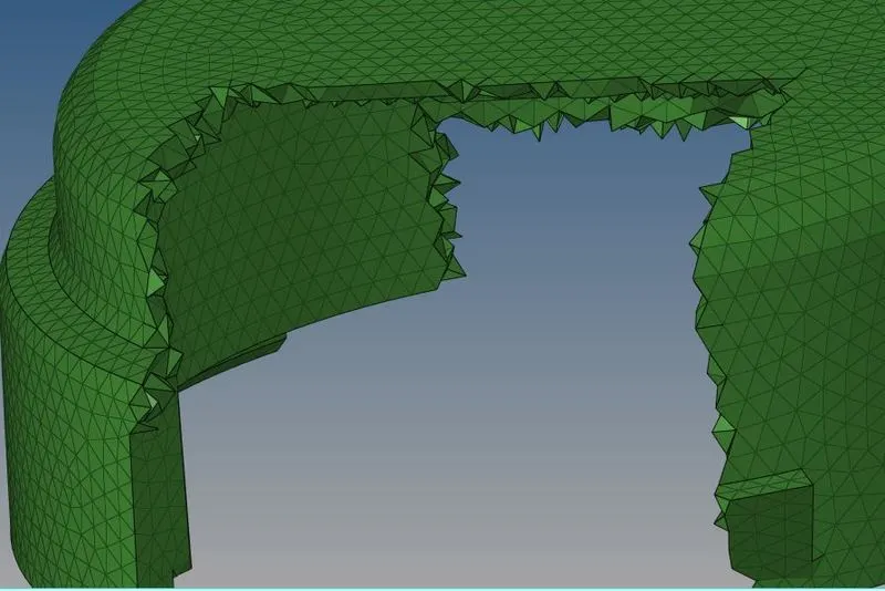 |
| Figure 8: Tetrahedral meshinig of Housing Component. | Figure 9: Tetrahedral meshinig of Housing Component. |
Also we have to make sure, there should be no kinks and dips on the surface of components. If we get any collapse, we have to rectify those elements by moving nodes manually. Some of the methods that can helps use for improving the quality of elements are as follow:
- Manual adjustment
- Tetra remesh
So, we have no TET collapse issues in both outer and inner components as shown in picture below.
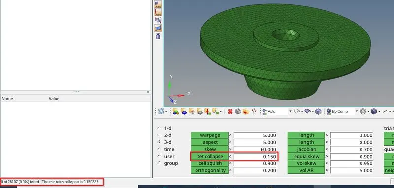 |
Figure 10 :Element quality checking |
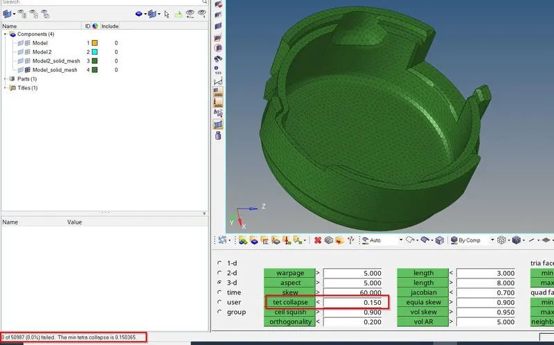 |
Figure 11 :Element quality checking |
B. CAD MODEL 2-ARM BRACKET:
Procedure:
1. To perform volumetric meshing with hexahedral elements for arm bracket:
Procedure to open Arm Bracket model is same as explained above for Housing model. Once model is opened, it will look like as shown in picture below.
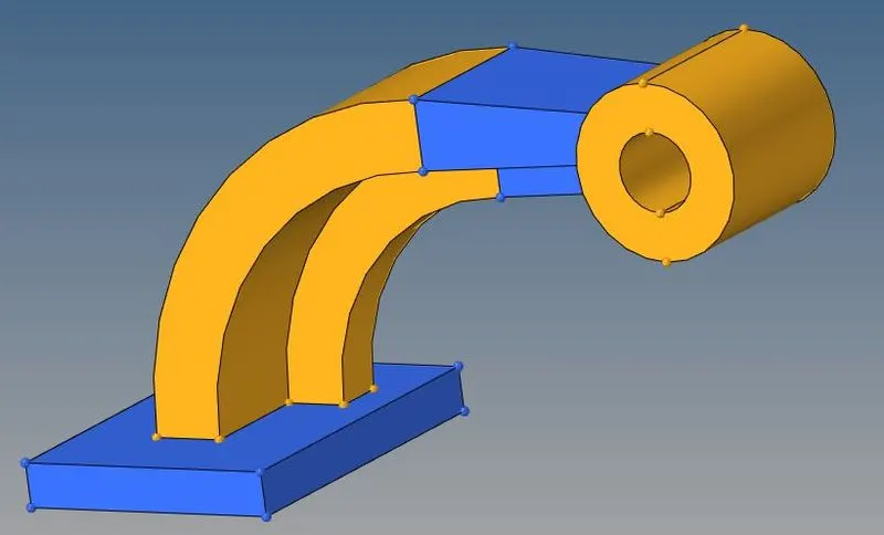
Figure 12: CAD model of Arm bracket.
2. By using Solid Map option
First we have to follow Hexa mesh on Base of arm bracket. In order to perform hexa mesh on base, we have to perform shell mesh on base with quad elements of target size 10mm as shown in picture below.
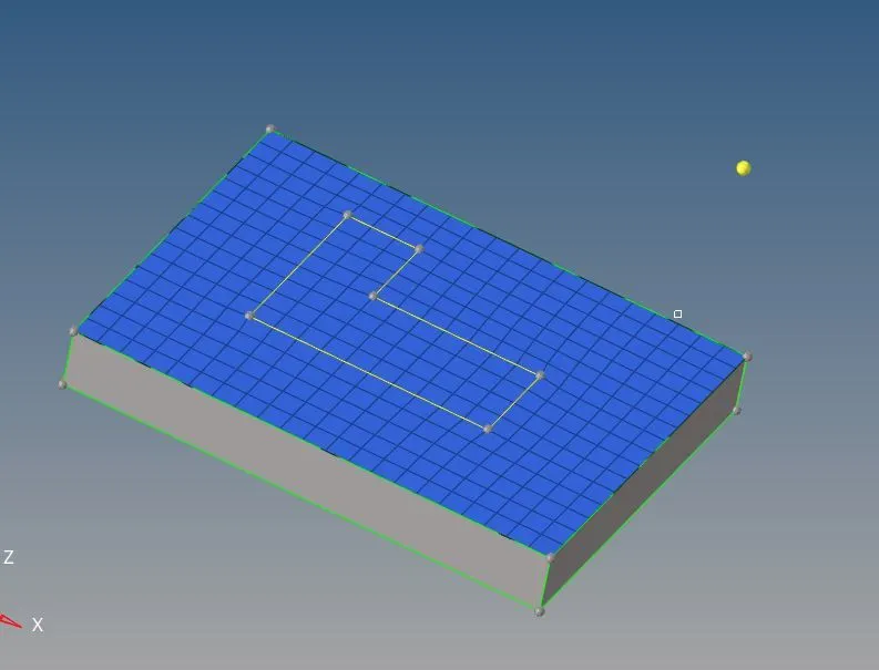
Figure 13: Hexahedral meshing of Arm bracket.
Now we have to select solid map option in order to create hexa elements by following:
3D---->solid map---->general.
First we have to select shell elements in “elems to drag” option. Now select bottom surface as “dest geom” and also select side surfaces as “along geom”. And finally have to click on mesh.
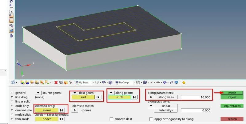
Figure 14: Hexahedral meshing of Arm bracket.
Once brick or hexa mesh is done, model will look like as shown in picture below.
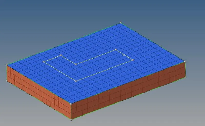
Figure 15: Hexahedral meshing of Arm bracket.
3. By using Spin option
Now we have to create hexa elements in arm curve. So in order to create elements along curve, first we need arc center about which elements have to spin. so, inorder to create center node, we have to follow.
Geom---->distance---->three points---->select points on arc---->circle center.
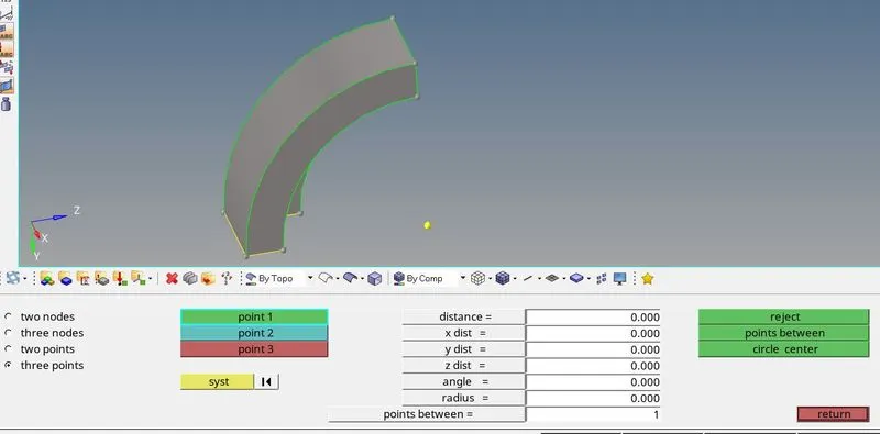
Figure 16: Hexahedral meshing of Arm bracket.
Now in order to spin Quad shell elements about arc center, we have to follow.
3D---->spin---->spin elems---->spin-.

Figure 17: Hexahedral meshing of Arm bracket.
Once spin operation is done model will look like as shown in picture below.
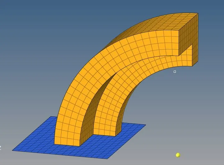
Figure 18: Hexahedral meshing of Arm bracket.
4. By using linear solid option
Now we have to create the shell elements with quad elements of target size 10mm at the front of arm straight as shown in picture below.
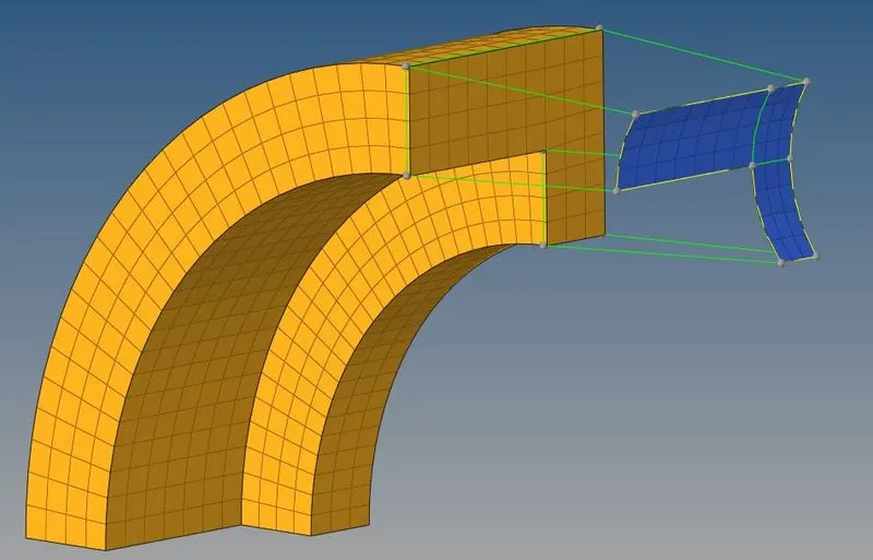
Figure 19: Hexahedral meshing of Arm bracket.
Linear Solid Panel helps to create solid elements between two groups of plate elements. Make sure to keep the number of elements same at both start and end of the objects. Now in order to use linear solid panel we have to follow.
3D---->linear solid---->solids.
In from element option we have to select the elements where you want the plot elements to begin. And in to element option we have to select the elements where you want the plot elements to end.
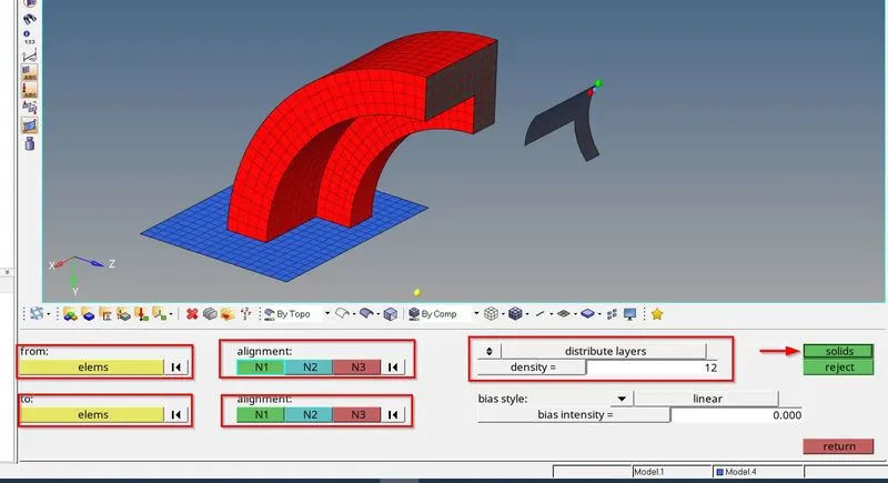
Figure 20: Hexahedral meshing of Arm bracket.
Once linear solid operation is done, model will look like as shown in picture below.
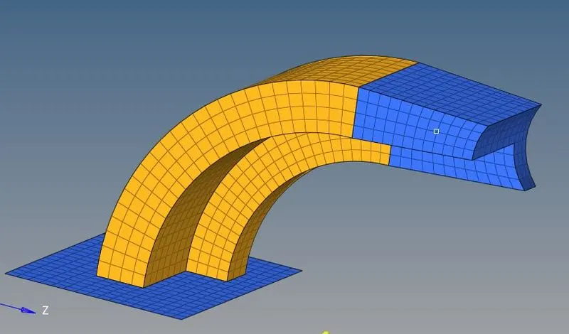
Figure 21: Hexahedral meshing of Arm bracket.
5. By using Solid Map option
Now we have to perform shell mesh with quad elements on top face of the boss. Then we have to project the shell elements to the bottom face of boss as shown in picture below.
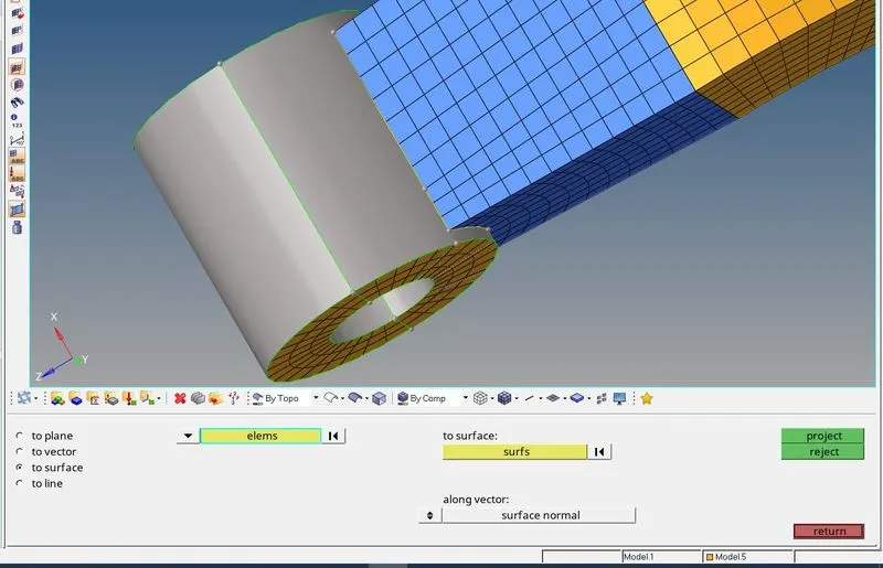
Figure 22: Hexahedral meshing of Arm bracket.
Now we have to use solid map option by following
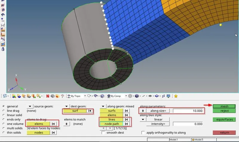
Figure 23: Hexahedral meshing of Arm bracket.
Once solid map operation is done model will look like as shown in picture below.
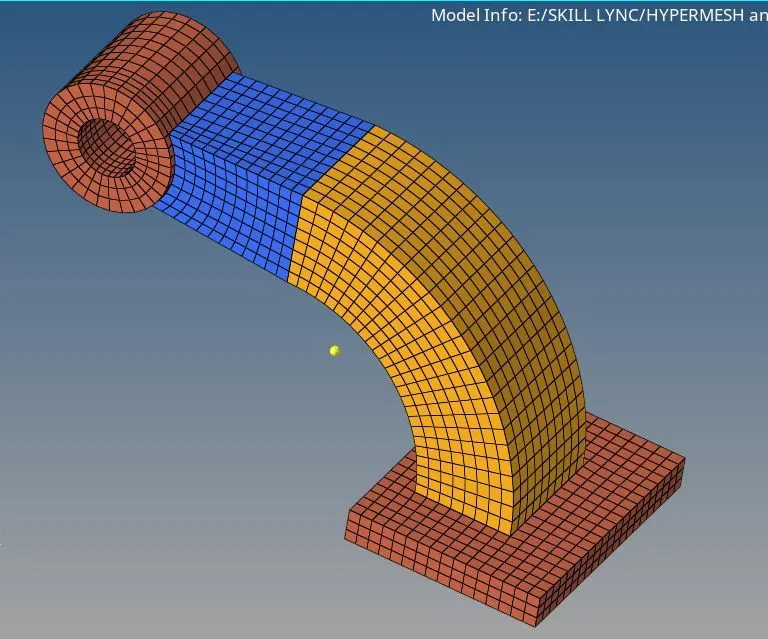
Figure 24: Hexahedral meshing of Arm bracket.
CONCLUSIONS
- Calculated the speed of sound in steel rail and also calculated the time taken by shock wave to travel in steel rail and edited the termination time and animation time step in engine file.
- Performed volumetric meshing with tetrahedral elements for housing component
- Performed volumetric meshing with hexahedral elements for arm bracket.