Assignment 2
- Objective:
- Using the material properties of the rail component, calculate the speed of sound in steel rail.
- Calculate the time taken for the shock wave to travel from one end of the rail to the other. The length of the rail is about 1000 mm.
- Time for sound to travel length of rail.
- Edit the engine file so that the stress wave can be monitored, moving from one end of the rail to the other during impact.
- Set the frequency of animation output to a time that will give 20 animation steps(/ANIM/DT).
- Change /print -10.
- 3d meshing tetra mesh and hex mesh on the given components with target tet size=5mm,hex size=10mm,tet collapse=0.15.
- Procedure:
To find the mechanical properties of the steel rail, we need to open the Starter Deck Input file which is the 0000.rad file. This file contains all the information of the model such as the properties of the
material, all the nodal id's, boundary conditions on the components etc. This file is readble by the user as it is text format. Open the file and find the properties of the material, so that we can calculate
the speed of sound through the rail.
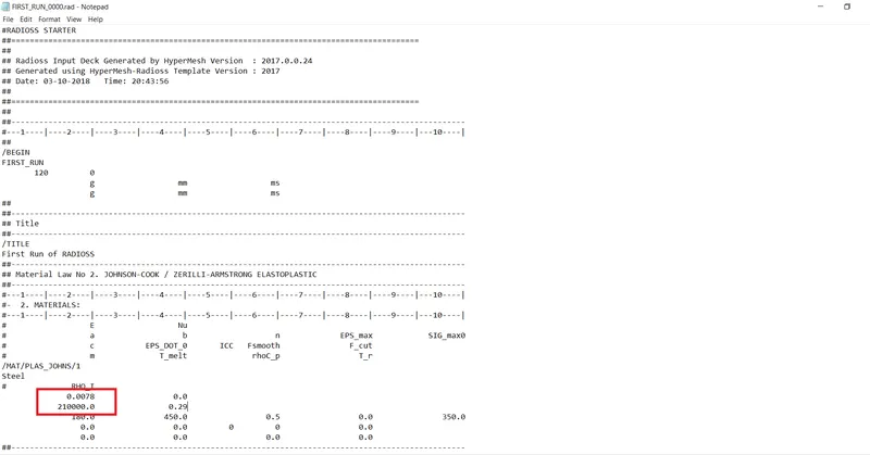
From the file, the Young's Modulus and Density for the material are found to be 210000.0 and 0.0078 which are the properties of steel. Using these properties, we can calculate the speed of sound in the rail.
- Speed of sound through in the rail = √(E/ρ)
= √(210000/0.0078)
= 5188.74
2. Now the time taken for the shock wave to travel from one end of the rail to the other can be calulated as -
T = length of the rail / speed of sound in the rail
= 1000 / 5188.74
=0.1927
3.Time for sound to travel length of rail = T = 0.1927 as the length of rail is 1000mm.
4. The engine input file runs and control the simulation and the selected variables to be displayed in the output file. For the stress wave to be monitored, moving from one end of the rail to the other during
impact, edit the Engine file. This will require the termination time shown below to be made equal to the time it takes for the sound to travel the length of the rail.
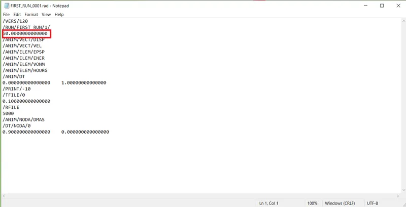
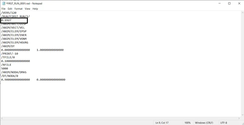
Set it to 0.1927
5. Setting the frequency of animation.
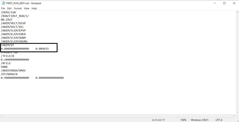
The frequency animation time for 20 animation steps can be calculated by dividing the termination time by the no. of animation steps. Then make the change in the 0001.rad file.
Tf = Termination time / 20
= 0.1927 / 20
= 0.009635
Now we can start with the next task, which is the 3D meshing of the given component. The given files are .hm file, which can be directly opened. Go to File > import > Model. Select the file and click on
open. The file will be opened.
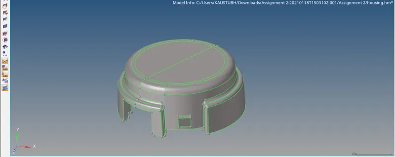
Check for any geometric losses in the component. Set the geometry color mode to By Topo and click on visualization icon. Check only Free edges and Non-manifold edges. Press F to fit to screen.
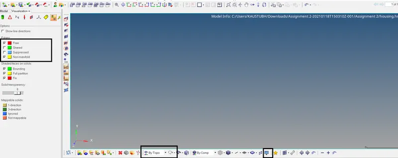
No error in the geometry is found. Also no geometry cleanup is required to be done considering the minimum element size. We can proceed to meshing the component. Go to 2D > automesh. Set mesh
type to trias and element size = 5. Select the displayed component and click on mesh. The component is now meshed with trias. Now go to 3D > Tetramesh > Tertramesh parameters. Set min tetra size
equal to 5 and tet collapse = 0.15. Check fill voids, fix midnodes and smoothing.
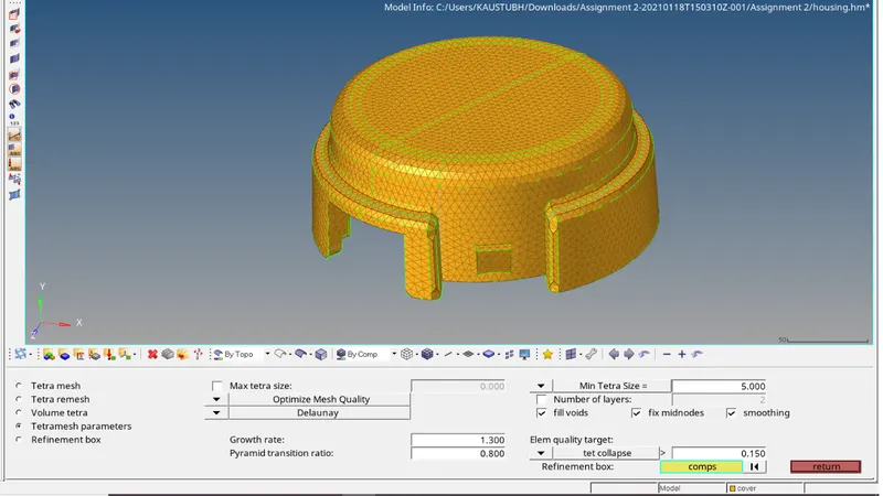
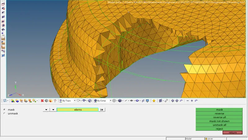
Now go to Tetramesh. In the Fixed tria selector, select all the elements and click on mesh. The 2D elements will now be converted into tetras as seen below.
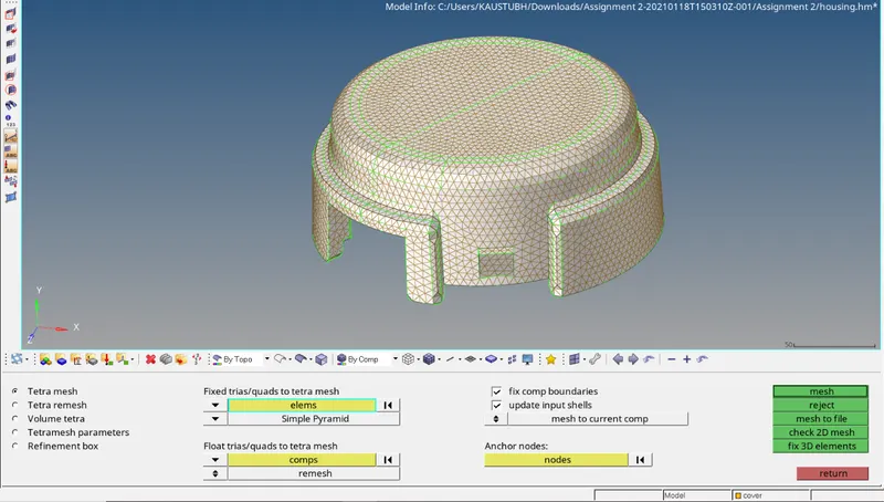
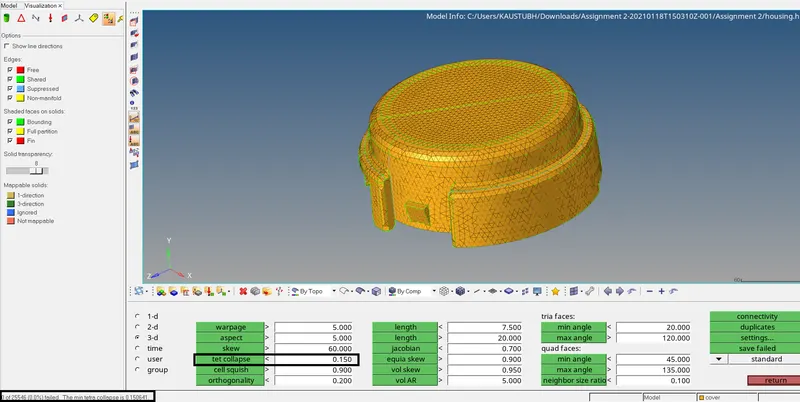
Now we can check the 3D elements failing for tet collapse. Press F10 to go to check elements panel and click on 3D > tet collapse. Set the value for min tet collapse = 0.15 and click on tet colllapse. 0
elements are found failing for tet collapse.
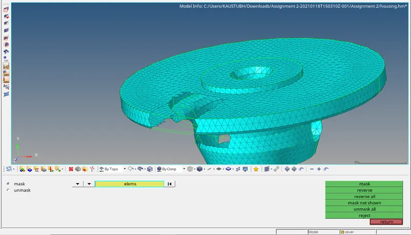
Now hide the mesh and turn the display on for hub component. The component is meshed with shell elements as seen below.
We have to maintain the quality of 2D elements as per given criteria and then convert the 2D elements into 3D. Go to check elements panel and check for failed elements. Around 2000 elements are found
failing for minimum height. Click on save failed. Press F5 and set the entity selector to elements. Right click on it and select retrieve and unmask adjacent elements.
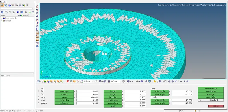
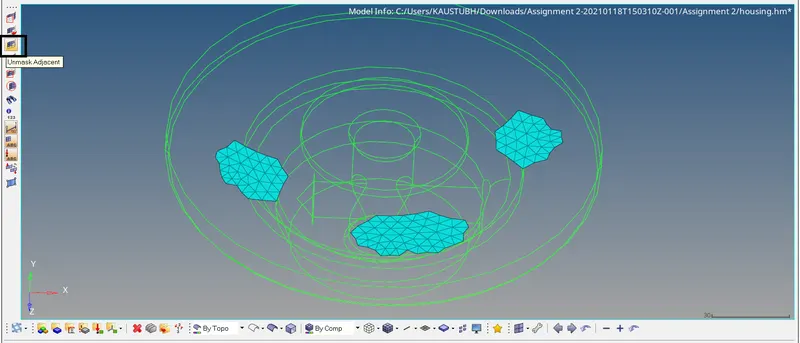
Remesh the failed elements with the adjacent elements so that the we can repair the elements failing for quality criteria. Reduce the failing elements to min as possible. All the elements are repaired except for
min. length as these elements are located in the areas where the surface itself is very small.
Now convert the 2D elements into 3D using tetramesh option discussed earlier.
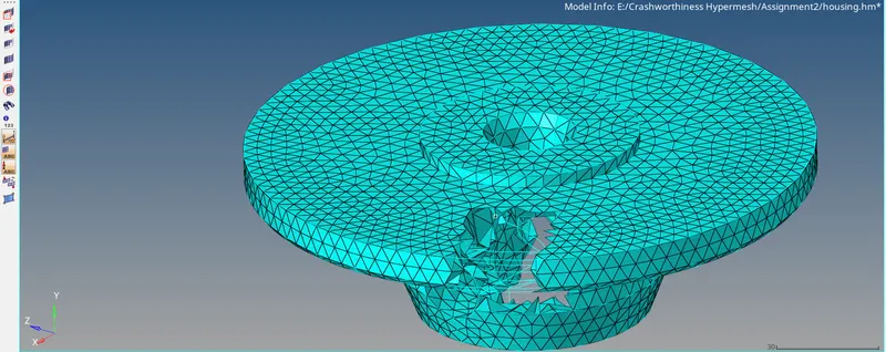
No elements are found failing for tet collapse.
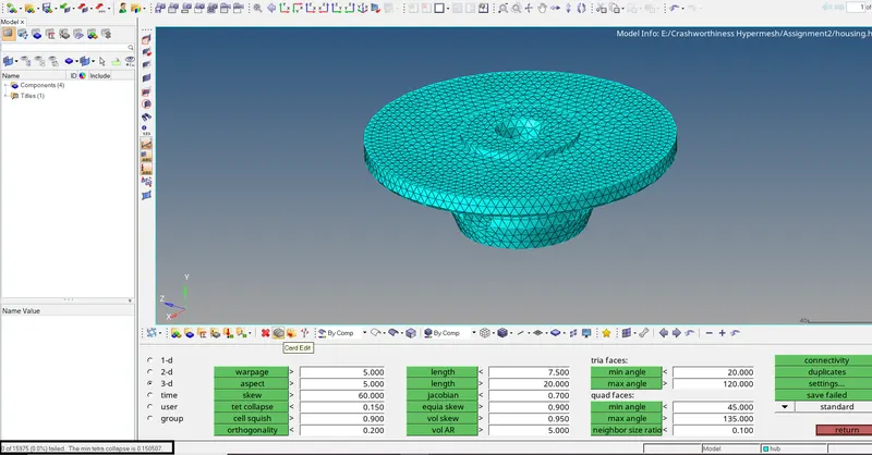
Now tetra meshing is completed. We can proceed with hex meshing for arm bracket. Open the file and isolate the base component. Mesh the surface with element size as 10 and element type as quad.
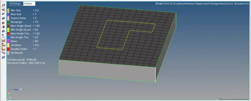
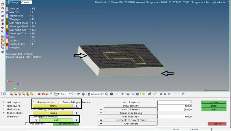
Now go to 3D > element offset > solid layers. In the 2d elements to offset select the displayed elements. In along geom to follow set the entity selector to surfs and select the displayed surface. Enter
num of layers = 5 and total thickness =25 which is the actual thickness of the base. Click on offset.
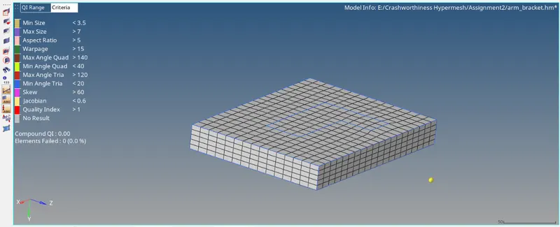
Make arm curve as current component.
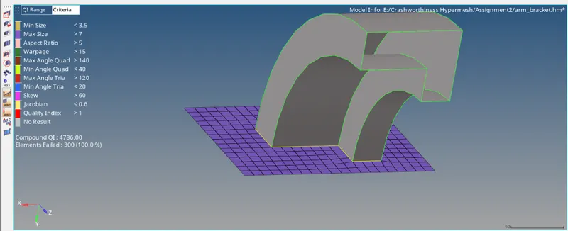
For the arm curve seen above, we can spin the elements in the intersecting portion as it is forming Non-manifold edge. First create centre of arc to define the centre of rotation.
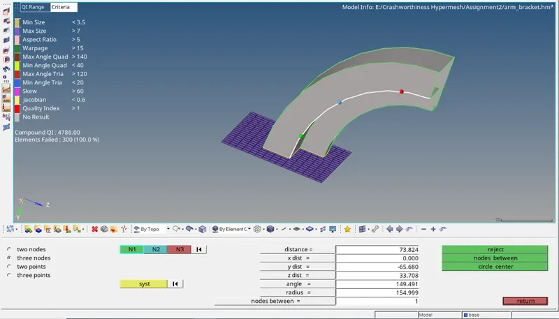
Press F4 to go to distance panel. Select 3 nodes option and create 3 temporary nodes on the edge as shown above. Click on circle center to create centre of circle. Now go to 3D > Spin.
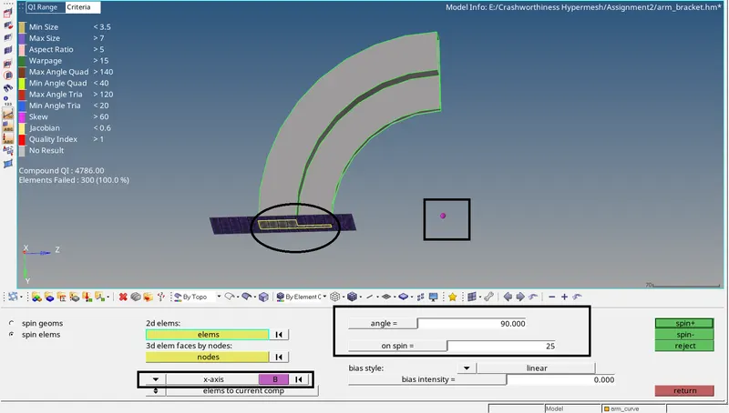
In the 2d elems selector, select the elements shown above. Enter angle of spin as 90. Enter on spin = 25 which is the no. of layers of element to be created. Select the axis of rotation as X axis and centre of
rotation the centre node which we created and click on spin -
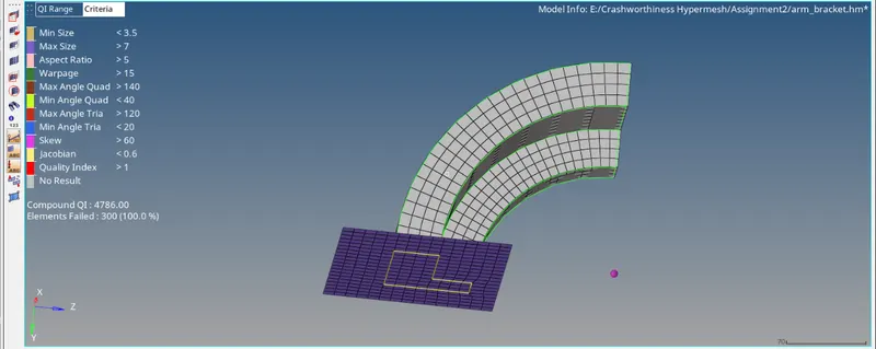
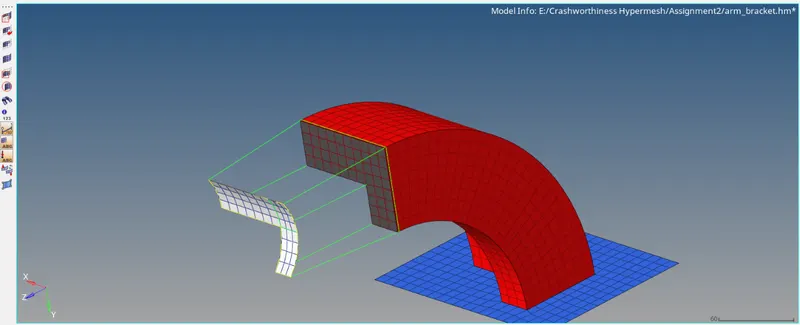
Now isolate arm straight component. As seen the component is extending from one end and linearly extending other side.
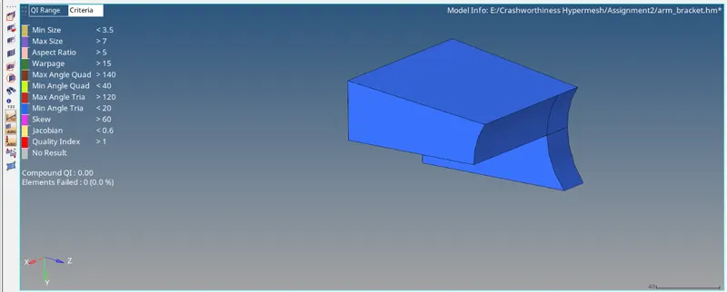
We can create same no of 2D elements on both ends and then create brick elements between them. We already have elements on one side from the spinned elements. We need to extract faces from the brick
element from one side. Go to Tools > faces. Select the arm curve component and click on find faces.
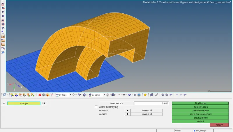
The 2D faces will be extraced as shown. Now create same no. of shell elements on the other side of arm straight.
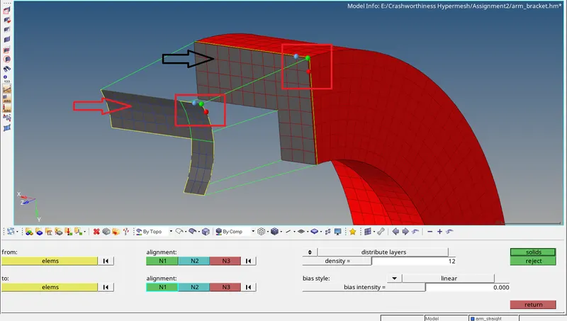
Now go to 3D > linear solid. In From entity selector, select the elements indicated by black arrow and in To entity selector, select elements indicated by red arrow. For alignment, select the nodes in same
sequence or order shown below in both the selectors. Enter density =12 i.e no. of element layer and click on solids. Brick elements will be formed as seen below.
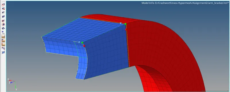
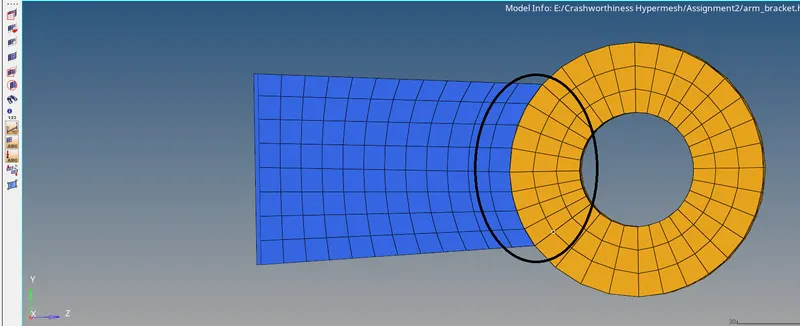
Now display off all the component except boss and arm straight. As seen, there are 8 elements on the surface of arm straight on the end portion. So we will create 8 elements on the surface of the boss in the
splitted region to match with the elements of the arm straight.
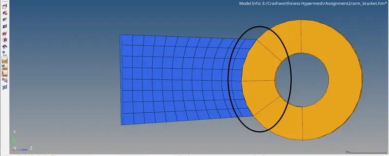
Go to 2D > automesh and mesh with quad elements as shown.
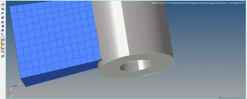
Now project the highlighted node on the bottom surface. This is done so that we can define the node path for the created elements to create brick elements.
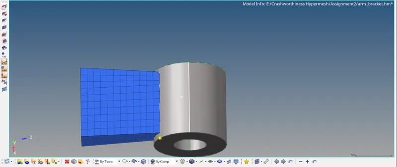
Now we can drag the created elements along the length of the boss. Go to 3D > linear solids > general. In the elements to drag selector, select the elements highlighed in black color. In the node path,
select the displayed nodes and in the lines selector, select the line shown in the rectangular box. Enter along size = 11 and click on mesh.
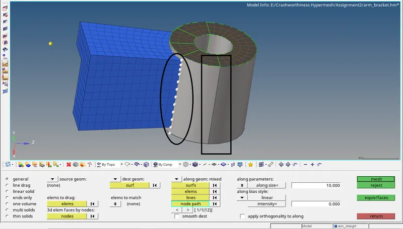
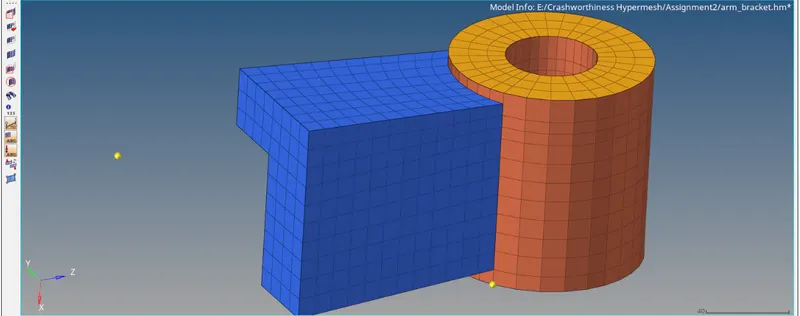
The brick meshing for the arm bracket is now completed. We can delete the quad elements which we created for creating the brick elements. Go to Delete panel > elements > By config. Select the config to
quad4 and type to CQUAD4. Click on select entities. All the quad4 elements will be selected. Now click on delete entities to delete the quad4 elements.
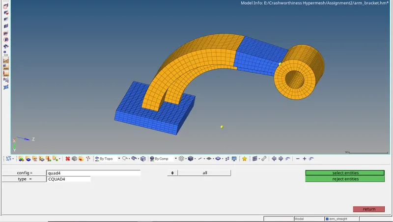
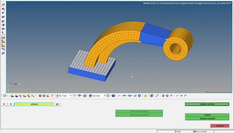
The brick meshing for the arm bracket is now completed.
- Outcome: We have learned how to calculate the speed of sound through a material using its properties and to calculate the time required for shock wave to travel from one end to another. We have also
learned how to read and modify the Starter Input Deck File to get the modal information such as loading conditions, material properties and the Engine Input File so that we can make changes to it to
get the output in the required form. Also we have discussed how to perform Tetra meshing using 2D to 3D method and how to perform brick meshing.