Assignment 2
AIM:
To perform tetra and hexa mesh on the given components and understand the radioss analysis
PROCEDURE:
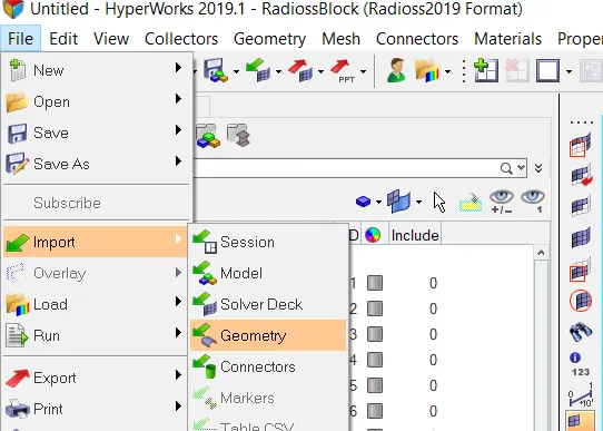
- First import the given component into the hypermesh.
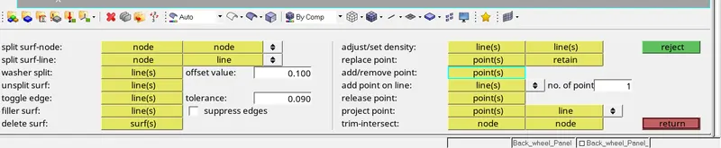
- Geometry cleanup the given components with the cleanup tools in the quick edit panel.
- Meshing the given componet in 2d by using 2d automesh option.
- After meshing the same components in 3d by using tetra mesh.
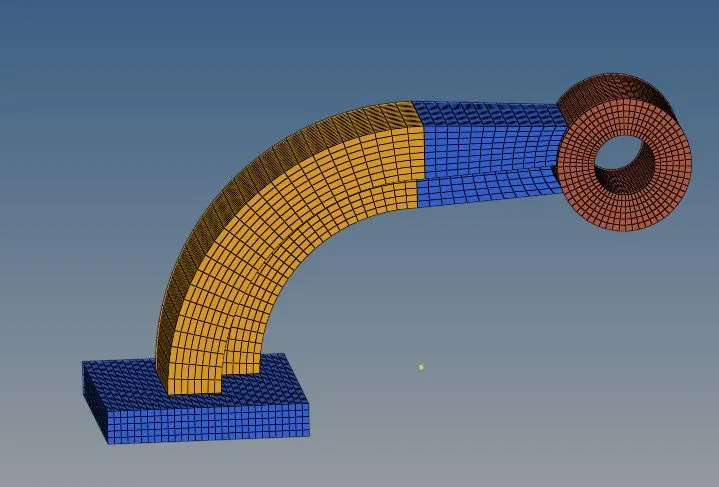
- Then meshing the arm bracket component in hexa mesh by using the tools in 3d like element offset, solid mesh etc.
STEP 1: IMPORT THE GIVEN COMPONENTS
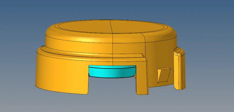
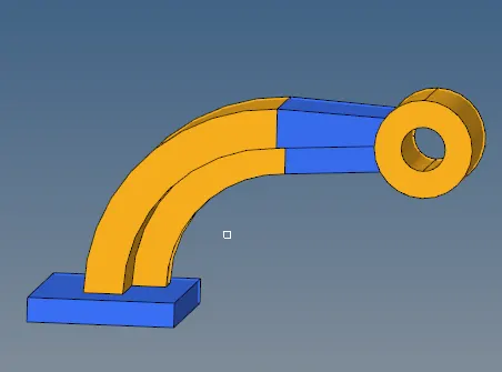
CAD MODEL IMAGE:
STEP 2: GEOMETRY CLEANUP
Before doing mesh, geometry cleanup the given housing and armbracket components .
STEP 3: 2D AUTOMESH
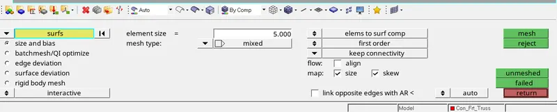
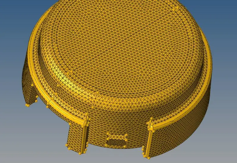
After geometry cleanup the given components, meshing the components.For arm bracket component use mixed mesh type to mesh the component and housing use the trias mesh type to mesh.Make a proper flow on the mesh of the components.
STEP 4: 3D TETRAMESH
- This option is used to create tetra mesh on the given components.
- After creating 2d mesh on the component,create tetra mesh by selecting its element.
- There is another option in there without creating 2d mesh on the component.
- we create tetra mesh by using the option volume tetra mesh.
- Then check the tetra elements for tet collapse in check elements option in tool.
- If elements are failure for tet collapse use fix 3d elements option in the tetra mesh panel.

STEP 5: CREATING HEXAMESH OPTIONS
3d > solid map > line drag
There are so many tools to create hexa mesh.This tool is used to create hexa mesh by using lines,nodes,surface.
First we create 2d mesh on the top of the surface and drag the mesh to create mesh on the component.
By using this tool we create tetra mesh with connectivity.

3d > element offset > solid layer
This option is used to create hexa mesh on the given component . After creating 2d mesh on the top like line drag selecting surface to drag the element to create hexa element.

3d > line drag
This option is used to create hexa mesh by using line. After create 2d mesh on the top surface use the line surface to drag it.

3d > linear solid
This option is also used to create hexa mesh. For that create both top and bottom side 2d mesh and select the plane to create nodes.

Mask option
This is mak option it is used to mask the hexa element.For that select configration mask and give hex 8 then give select entities it will select and mask it.

3D > SPIN
This tool is used to create hexa mesh on the angled componet. For that first i create a center node by using distance tool in that using the three nodes to create center node.Then selceting the nodes as a base node, give angle as 90deg and give spin it will create mesh in the angled part.

STEP 6: CHECK ELEMENTS
tool > ckeckelements > 3d
After creating tetra mesh ckeck the elemnts for tet collapse

FINAL MODEL IMAGE:
Radioss analysis:
1. Check the material properties of the rail component and calculate the speed of sound in steel rail=
Young's modules = 21000g/mm^2
Density= 1000g/mm^3
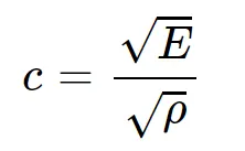
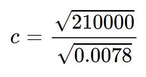
c =5188.74mm/sec
2.The length of the rail is about 1000mm. calculate the time takes for a shock wave to travel from one end of the rail to the other
Length = L =1000mm
speed = C = 5188.74mm/sec
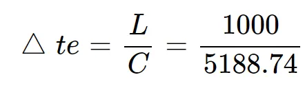

3. Time for sound to travel the length of rail = 0.19272 sec
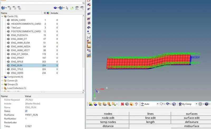
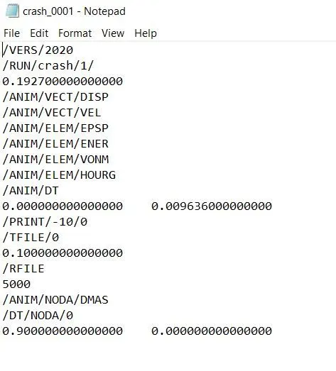
4.Edit the engine file so that the strss wave can be monitored, moving from one end of the rail to the other during an impact- this time its takes for the sound to travel the length of the rail (set on/RUN card)
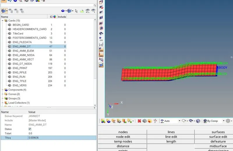
5.Set the frequency of animation output to a time that will give 20 animation steps(/ANIM/DT)
Frequency of animation = f = 0.1927/20,
Frequency of animation = f = 0.009636Hz
6.Change /print -10.
CONCLUSION:
I uderstood how to create 3d tetra mesh.
I understood how to create 3d hexa mesh.
I understood how to calculate critical time and frequency.
RESULT:
Create tetra and hexa mesh on the componets are completed and radioss analysis question are solved .