Hexa meshing in Hypermesh and Editing the Engine file
Assignment 2 Report.
- Objective: 1. To check the Material Property for the given Starter File and Calculate the Speed of Sound in that material.
2. Calculate the time taken for sound to travel the length of the rail.
3. Edit the Engine file according to the questions given.
4. To perform Tetra Meshing on the given component.
5. To perform a Hexa Mesh on the component. - Procedure:
1. For the first question, we need to import the starter file in Hypermesh while we keep the RADIOSS as the Solver. To import a starter file, we need to be in the RADIOSS Solver and then click on the Import option (the green icon as marked.) In this option we will get another icon of a file (also marked). We need to select the required starter file and import this file into the Software.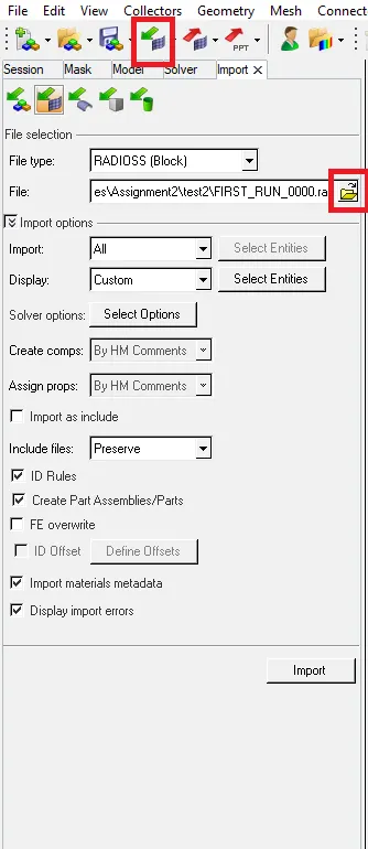
Importing process.
After we impot this file we then simply need to click on Materials in the Model Tab and the click on the material provided, Steel in this case.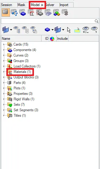
Checking Material Properties.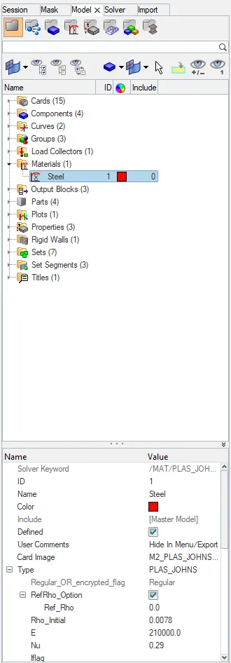
Material Properties
As we can see all the various properties such as the Density, youngs modulus and even the poissons ratio of the material of the material in the other tab that opens up.
So now to caculate the speed of sound for the material (Steel) we only need the Youngs modulus and the Desnity of the material. In this case The youngs modulus is given as 21e+4 GPa and the Density is given as 0.29 M Kg/L. And the formula to calculate the Speed of Sound for a material is given by:
`root`(Youngs Modulus/ Desity)
So here it will be `root`( 210000/0.007)`
Hence the value of Speed of Sound will be 5188.7452 `ms^-1`
2. Since the length of the Rail is given as 1000mm, and we need to calculate the time taken for the shock wave taken to travel from one end of the rail to the other.
We know that the shock wave travels at the speed of sound for that material. Since we have already calculated the speed of sound for this material, we can use the formula of
Speed = Distance/Time
From this we can conclude that Time = Distance / Speed.
In this case the Distance is 1000mm which is 1m and the speed is 5188.75ms-1
So,
Time = 1 / 5188.75
= 1.94e-4 s
= 0.194 ms (this is the unit for time because the other units were used on the similar scale.)
3. In this situation where we have to calculate the time for a Sound wave to tavel the length of the Rail, we simmply need to use the
Speed = Distance / Time
Here we have the Distance as the Length of the Rail which is = 1000mm or 1m.
The Speed for a sound wave to travel through the given material (Steel in our case) = 5188.75 `ms^-1`
Hence the Time Taken will be: Distance / Speed
= 1 / 5188.75 s
= 1.94e-4 s or 0.194 ms
5. And now to begin with the Tetra Meshing on the given component, the very first step in this process is to delete the solids present in the model. To do this, we can use the delete command (shortcut-F2) and use the solids option in it.
Solids Delete command.
The next step would be to perform a geometric clean up on the model. To do this, we need to switch on the "Display all fixed points" option on the Left hand side of the screen. Display nodes command.
5.2 After this option is enabled, we need to measure all the possible distances between the edges where the element (tria in this case) might fail for minimum element length Quality criteria. When these edges are found, there are multiple ways in which they can be corrected, one such method is to simply toggle the edge if it is not disturbing the feaeture of the model. To do this, we can use the Quick Edit Tab (shortcut-F11) and use the Toggle Edges options.
Quick Edit Tab.
5.3 After the model is Geometrically cleaned, we need to proceed to mesh the component with tria elements. To perform a 2D tria meshing on the component, we can use the automesh command in the 2D tab (shortcut-F12). We need to alter the target element length and the meshing elements before we go ahead with the meshing process.
2D -> Automesh.
Automesh Command.
5.4 After the 2D Meshing is performed on the surface, we need to check for the Quality errors in the model. To check them, we need to use the Check elements command in the Tools Tab. We will give the necessary inputs and check for every criteria given.
Quality Check.
If at all any elements are failing then we need to resolve them using the cleanup tools in the Quality index command under the 2D tab.
2D -> Qualityindex.
Quality Index command.
5.5 After all the Quality criteria was cleared, then we need to move to coverting them into 3D Tetra elements. To do this, we can use the tetramesh command in the 3D tab in the pushpanel.
3D -> Tetramesh.
TetraMesh command.
We need to select the elements and then give in the Tetra mesh to the component. We can confirm if the tetra mesh is done or not by simply masking the 2D surface elements. To do this, we can use the mask command (Shortcut- F5) and mask the elements to see the Tetra elements in the model.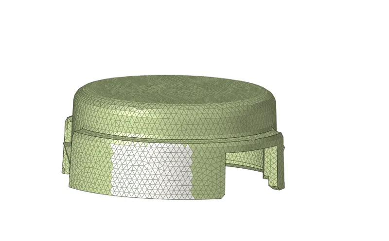
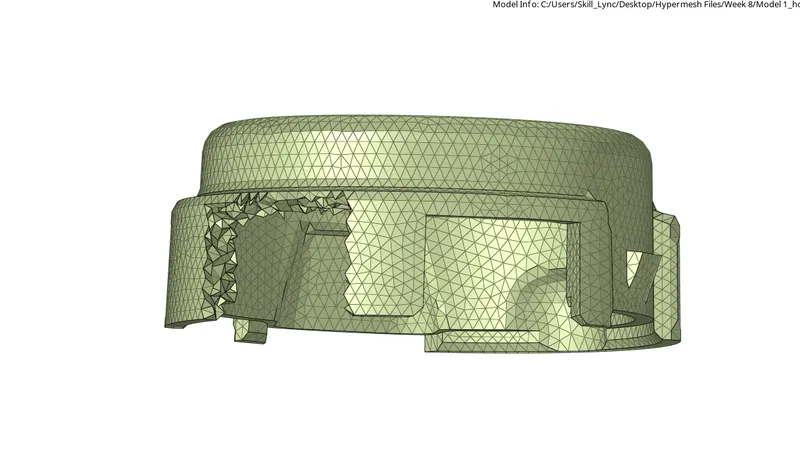
5.6 After the 3D Meshing is done, we need to check for Tet collapse error in the 3D Meshed tetra elements. We can do do this by using the check elements option and checking for the tet collapse option under it.
Checking for Tet collapse.
We can see the number of elements that have failed for that particular Quality criteria by simply clicking on it. The number of elements appear on the bottom left hand side of the screen.
Number of tet collapse failing elements.
Since my Quality criteria had been cleared with the 2D elements, we get 0 tet collapse errors in the 3D elements.
After the Tet Collapse error has been cleared, the model is said to be meshed with 3D Tetra elements.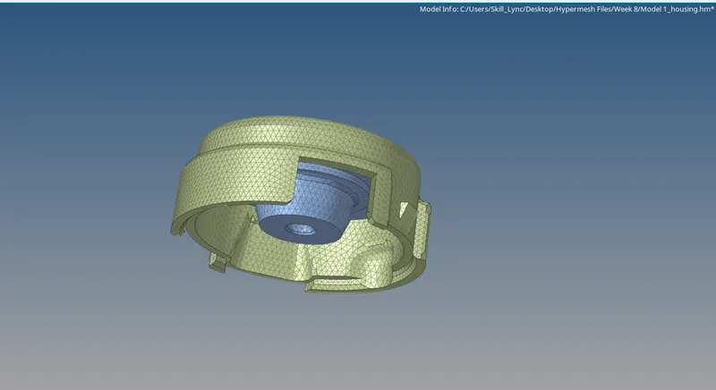
Final Meshed component.
6. Now to perform a Hexa Mesh on the given component 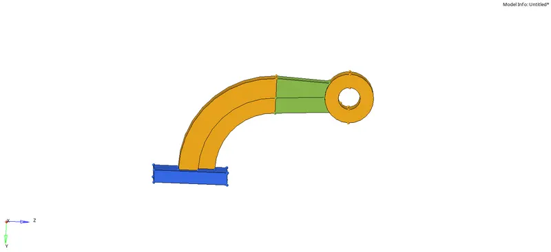
Initial Model.
To start the Hexa Mesh on the component we need to use the 3D tab and use the various options in it. Some of the options are Solid map, Line drag, etc.
3D -> Hexa Mesh options.
6.1 We need to start at the Base of the component. We need a 2D Shell mesh to perform the 3D Hexa Mesh, so we will firstly mesh the base surface with a proper Quad Mesh (No Tria and Rotating Quads in the Mesh.) To mesh the base surface with Quad elements we need to use the Automesh command (shortcut-F12).
2D Mesh options.
Please note that we will mesh with the mixed type of elements and then go on to remove the Tria elements from the base. We also need to check the Flow Align and size option to get a better Mesh flow.
After meshing the surface we then drag the elements along the line to forming proper Hexa Elements along the Surface. To do this we need to use the Solid Map command and use the Line drag option in it. In this option we need to give the 2D elements as an input and the line along which the elements are to be dragged along.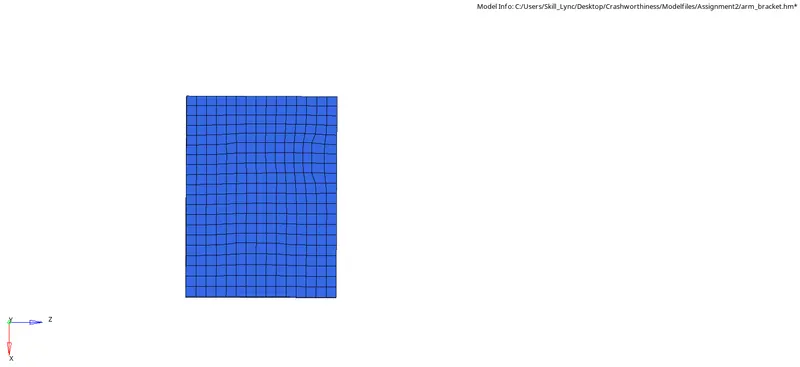
Before Line Drag.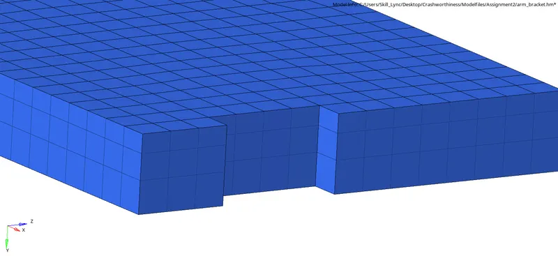
After Line Drag.
Another command that we can use when meshing the component with 3D Hexa Mesh is the command of Spin in the 3D tab. To use this command we need to plot the circle center of the arm curve component. To do this, we need to use the nodes command in the Geometry tab. In the nodes command, we need to use the option of arc center.
Geometry -> Nodes.
Arc Center command in Nodes.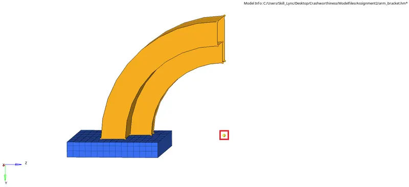
Arc Center Created.
So, when we use the Spin command, we firstly need to select the 2D elements on the base that are coincinding with the Arm Curve component and then set the angle as 90degrees and set the on spin as 25 (This is the number of elements that will be formed on the arm curve component.)
Spin command.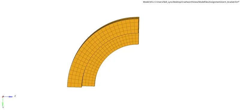
Spin Command Output.
The next command we can use is the command of Linear Solid under the 3D Tab. In this command we can simply map elements if the number of nodes on the edges are equal and if the Shape of the Geometry is similar. As we can see that the goemetries in this case are almost similar.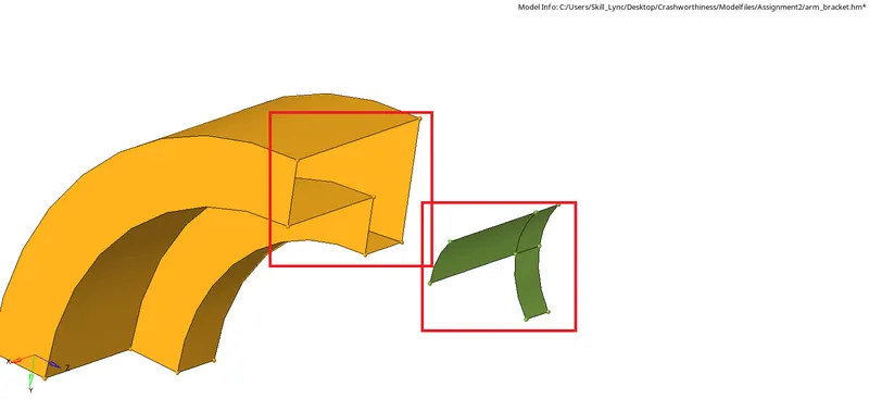
Similar Geometries for Linear Solid.
In this, we can map the elements from the first geometry to the next geometry. So the "From" elements are the elements from which we need to extend the elements and the "To" elements will the elements on the Second Geometry. In this command we need to carefully select the N1,N2, and N3 nodes on both the First and the Second Geometry.
Note: We need to equal the number of nodes on the similar edges.

Linear Solid Command.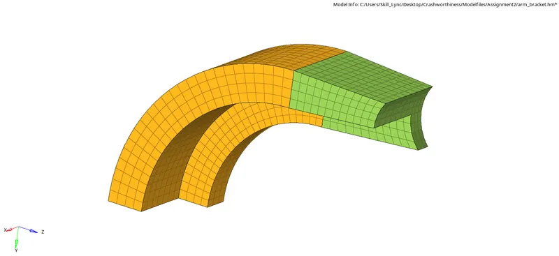
Linear Solid Output.
Using such operations we can complete the entire model with a proper Hex Mesh.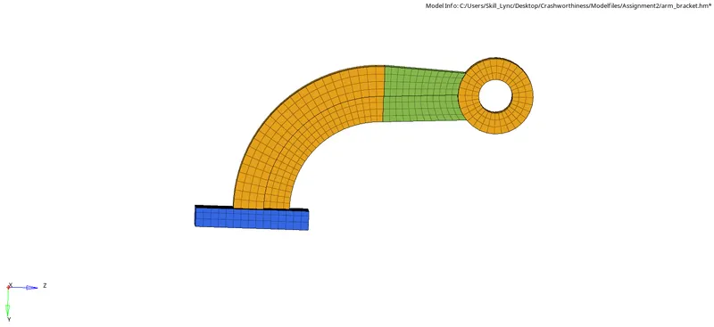
Final Hexa Meshed component.
7. To now according to the fourth question, we need to terminate the simulation when the time becomes equal to the time it takes for the sound to travel the length of the rail.
We already know the time for the sound wave to travel the distance of the rail is = 0.193 ms.
Hence our run time needs to be this exact value. So after importing the file, we need to select the Model tab and then select the ENG_RUN file and then change the Tstop to 0.193 ms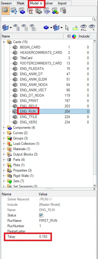
Changing the Run time.
And the next step is to run this file while we have the tfreq set to 1. We can check this tfreq in the ENG_ANIM_DT File.
And after running this file we get a number of Animation files in the main file directory.
So, after a particular number of iterations, we understand the following Formula:
Run time / Number of Animation file = Tfreq
So, According to this, my Tfreq. will be of the value = 0.00965
Like this we can alter the number of animation files that will be formed after the simulation and the frequency to be set.
- Conclusion: In conclusion I would like to state that this assignment helped me gain a better overall look of how to run a simulation in the RADIOSS solver and how to alter the number of Animation files according to ones need.