3D MESHING ON GIVEN COMPONENTS
AIM:-To perform box and Hexa mesh of given component and to understand radioss analysis.
PROCEDURE TO PERFORM 3D MESH:-
- First, we need to geometry cleanup
- Then after we need to give quality criteria
- After that, we need to perform mesh
- Then save the file in.hmw file
GEOMETRY CLEANUP:-
- First, we need to clean the geometry.
- To clean the set view to visualization and set geometry color mode to mixed.
- See whether errors are present we need to clear them.
- If errors are not present we need come to move further mesh.
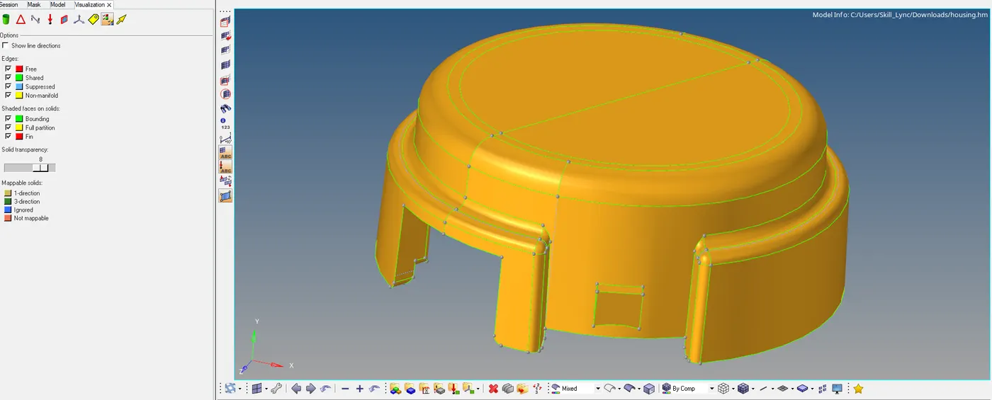
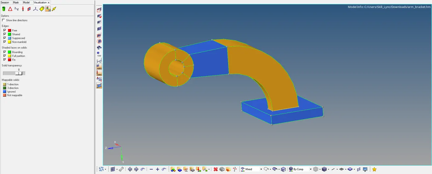
- Two objects are free from errors we can proceed further
MESHING:
- For the parts which are greater than 6mm, we need to do solid meshing.
- There are two types of meshing one is structured mesh one is an unstructured mesh.
- After meshing makes sure that we do not have any tetcollapse issue.
UNSTRUCTURED MESH:-
- From the name itself, we can understand the mesh is unstructured.
- To perform this mesh we must follow the process first we need to do perform a 2d mesh of trias/R trias.
- After that, we need to convert it to volume by those 2d mesh formed on the surface.
- There majorly three ways to perform mesh two are automatic and one is manual.
- Before any mesh, we need to give quality parameters and give the target element size and click on apply.
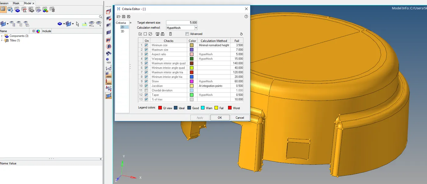
- After that, we need to do mesh on the surface with trias as mesh
- Go to 2d select auto mesh and then select surface and set mesh type as trias and press mesh
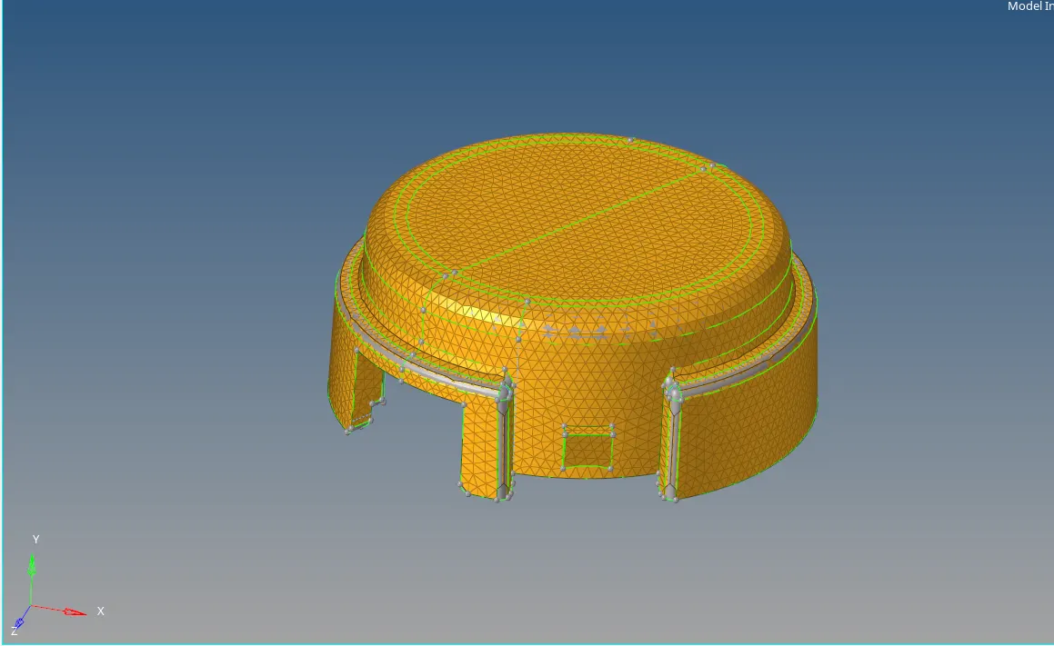
- Then we need to do 3D mesh for that we need to go 3D select tetra mesh and select tetra mesh.
- select the element and mesh them.
- Before mesh, we need to set mesh parameters in it.
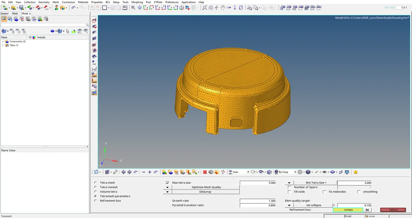
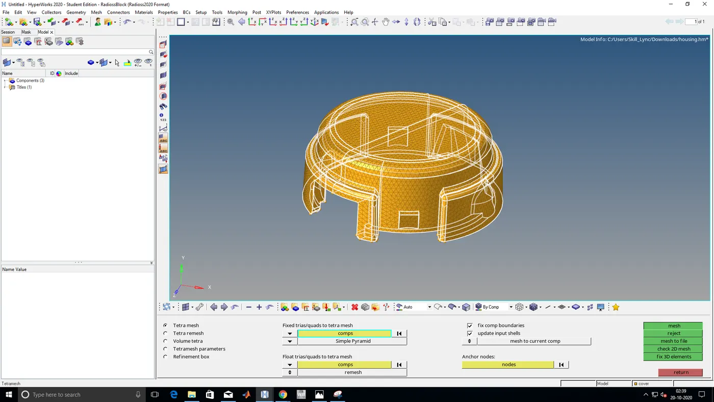
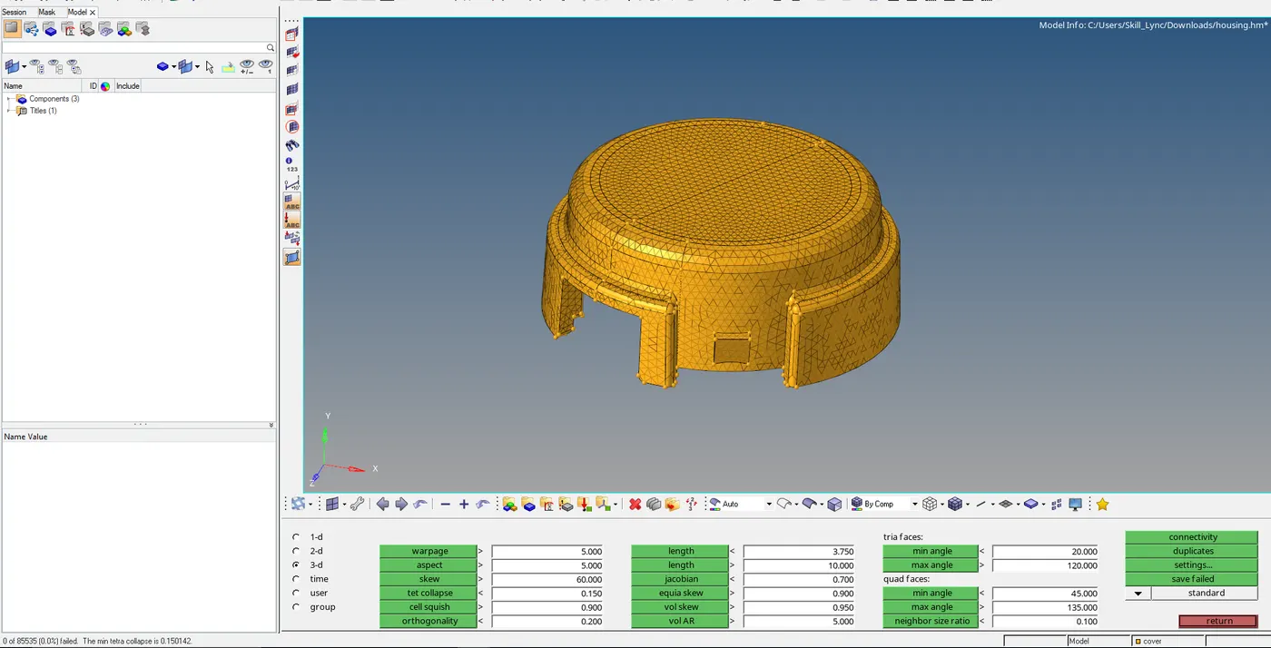
- Mesh done perfectly no quality issues
- If any issues we need to fix them by remesh or by going again to tetra mesh you can fix 3d elements
- Open that file and set the target element size and give parameters that to we resolved and then set fix quality
- After we need to select show elements failed and then select to fix it.
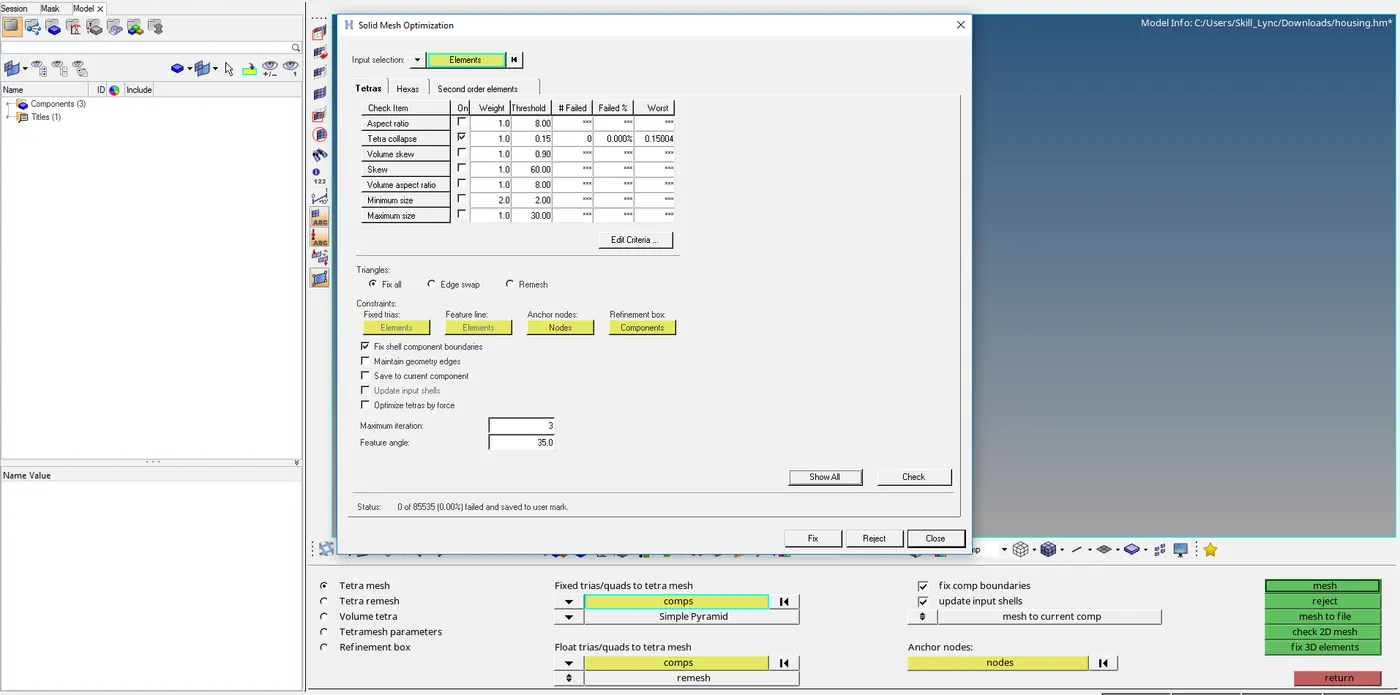
- The other method just goes to volume tetra and select component and give the mesh.
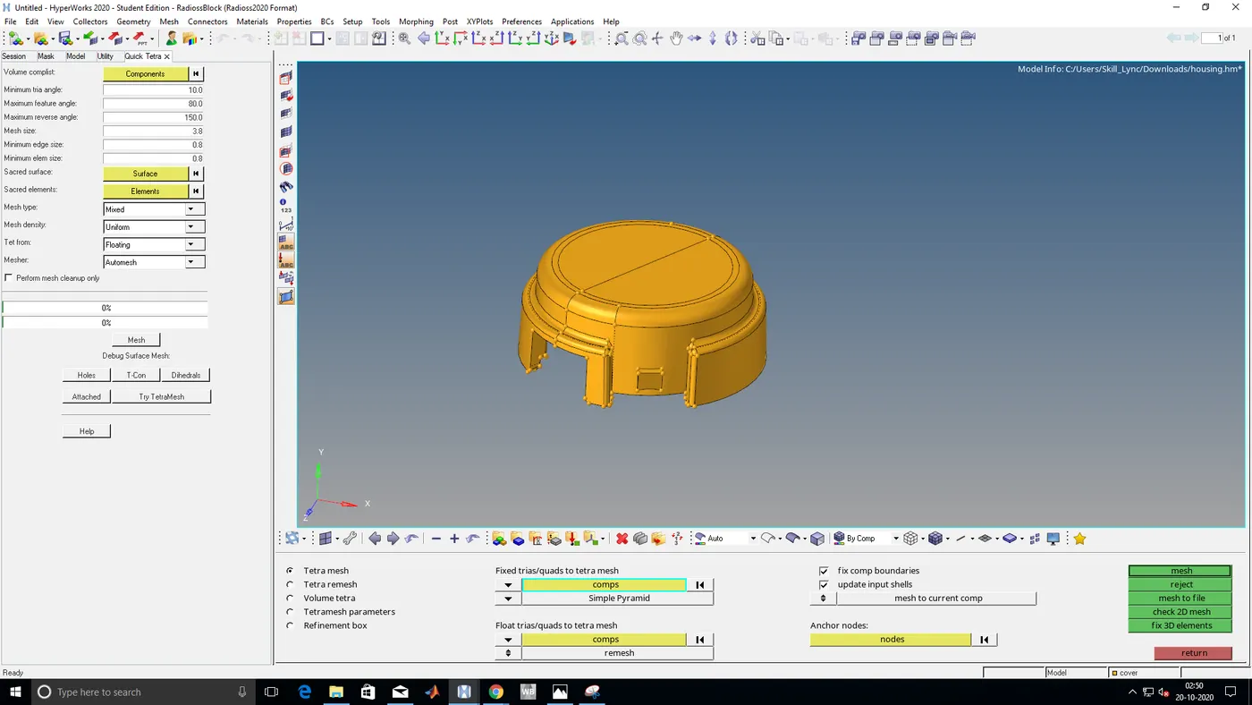
- The automatic mesh we need to go to view browser select hyper mesh utility and go to geo/mesh select quick tetra
STRUCTURED MESH:-
- This mesh is also called as Hexa mesh or box hexamesh.
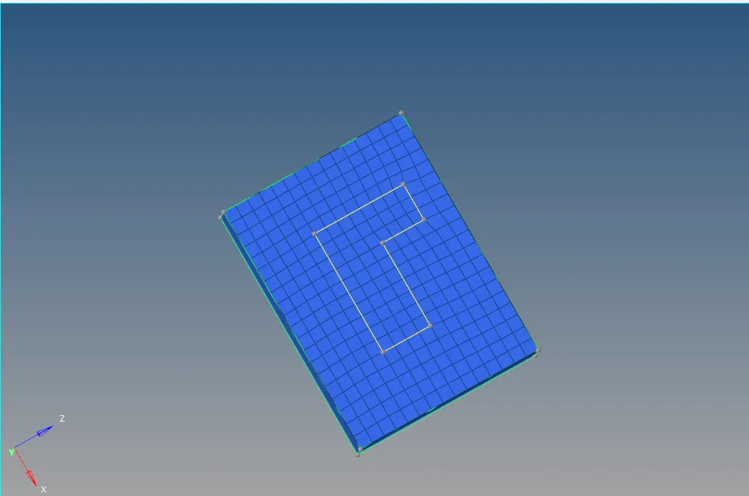
- In this type of mesh, we need to make 2d shell mesh drag them to the entire geometry
- Make sure that we need to have the only quad if it is rotating it is fine
- Make sure that make component current when you are going to do volume mesh
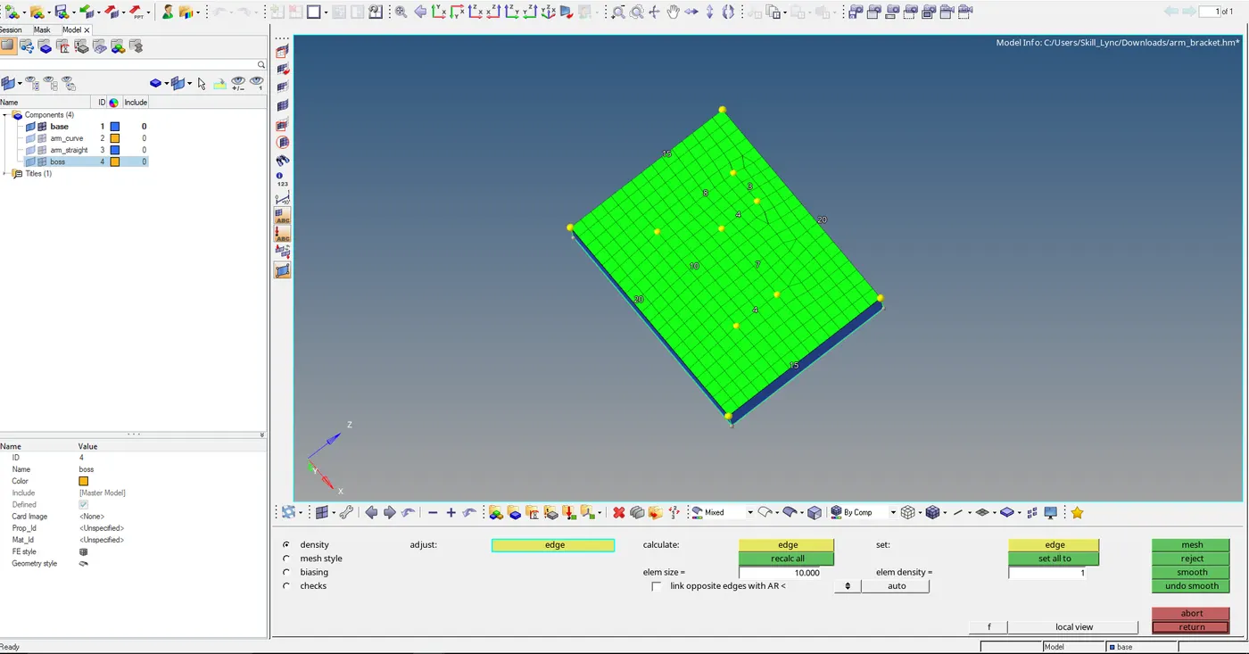
- Eliminate trias or make mesh style as a quad and mesh it.
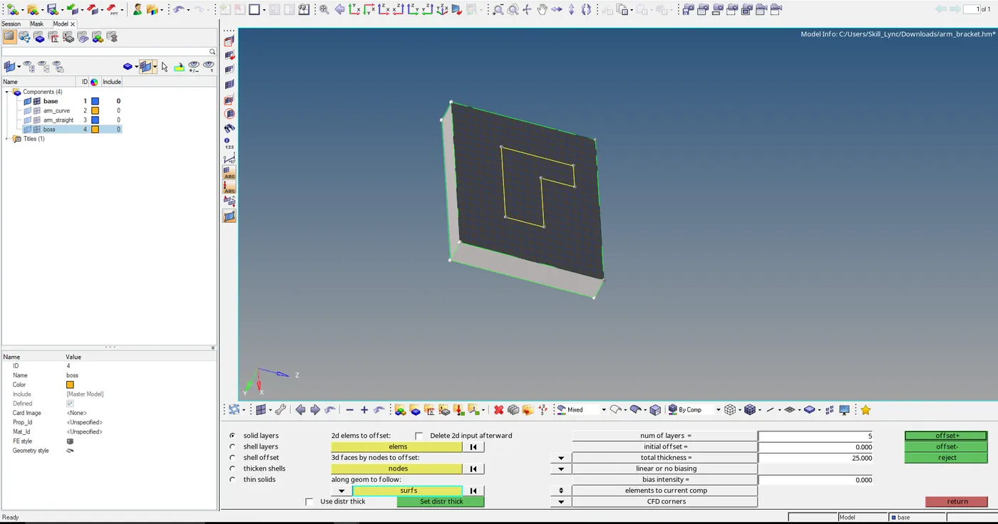
- To drag it to the bottom we need offset elements in 3d
- Select the elements need to be offset and then give thickness and assign the number of layers do u need
- Then after we needed to give direction to extended by selecting side surfaces
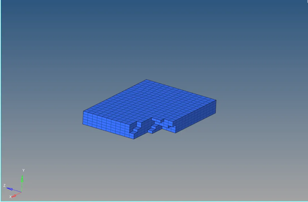
- The parts in curvature we need to spin then by using 2d mesh
- First, we need to go to mask and select elements in elements select config and select hex8 and select mask and reverse
- we need to create a center point arc for the elements to make it spin
- Go to node select arc center and select any line and click enter center node will be created
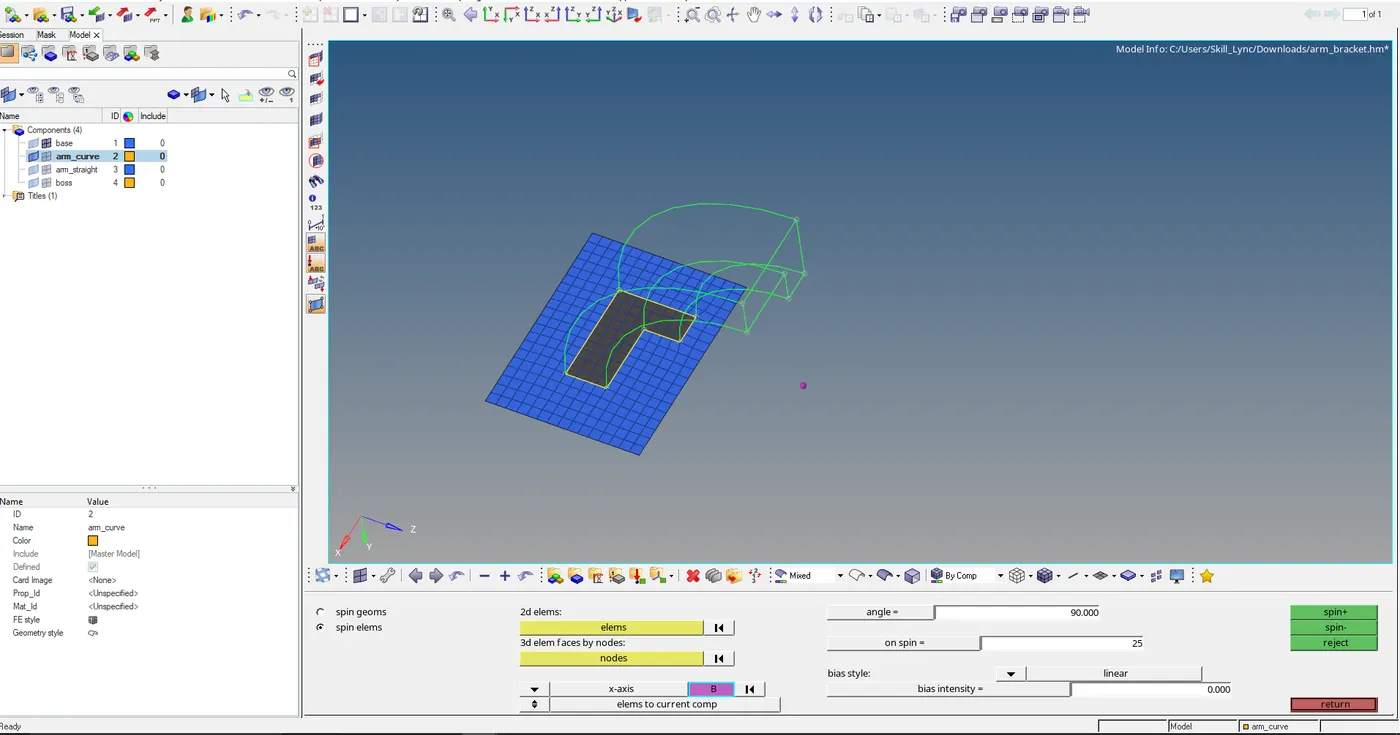
- Then select the elements and go to spin in 3D select the 2d element to be formed
- And select the normal axis and select the base node as the center and select the angle as 90 and give the number of layers needed.
- And select spin.
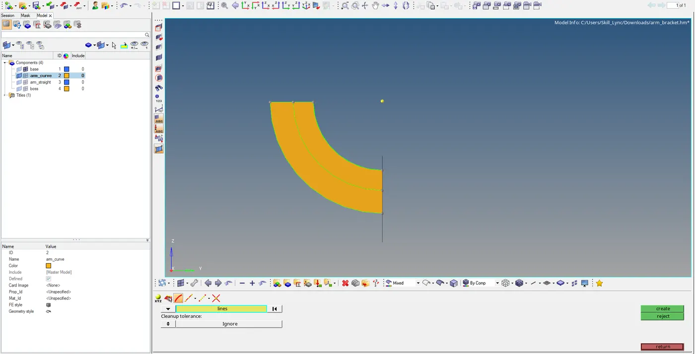
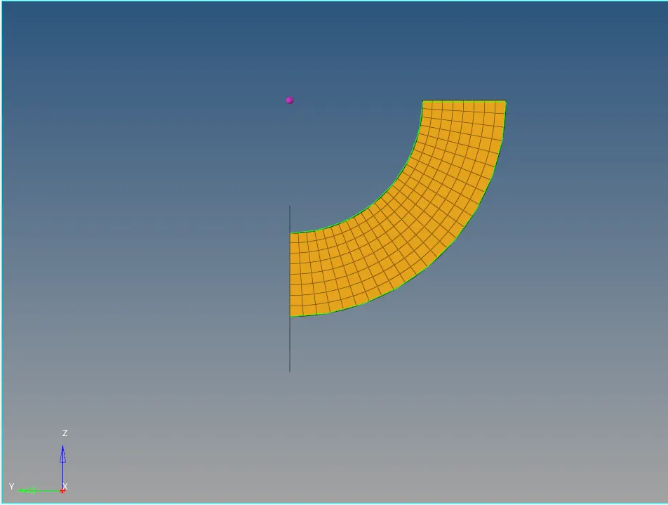
- The next subpart is a taper to make it hexa8 we need a2d element so we need to make 3d arm curve to face
- Go to tools and select the face and select the arm curve and select the faces and then turn off the mesh of the arm curve
- Now to extend we need to follow linear solid make sure the fact that to be extended the be meshed with the same node.
- Select the element to be extended in arm curve and select the opposite elements to be joined and give alignment of two faces
- And we need to set layers and select.
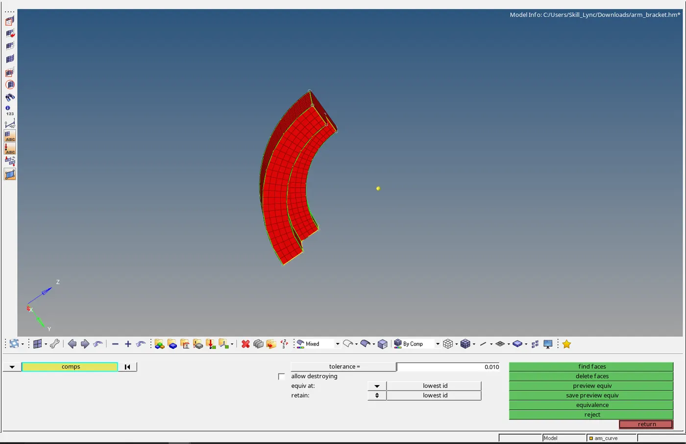
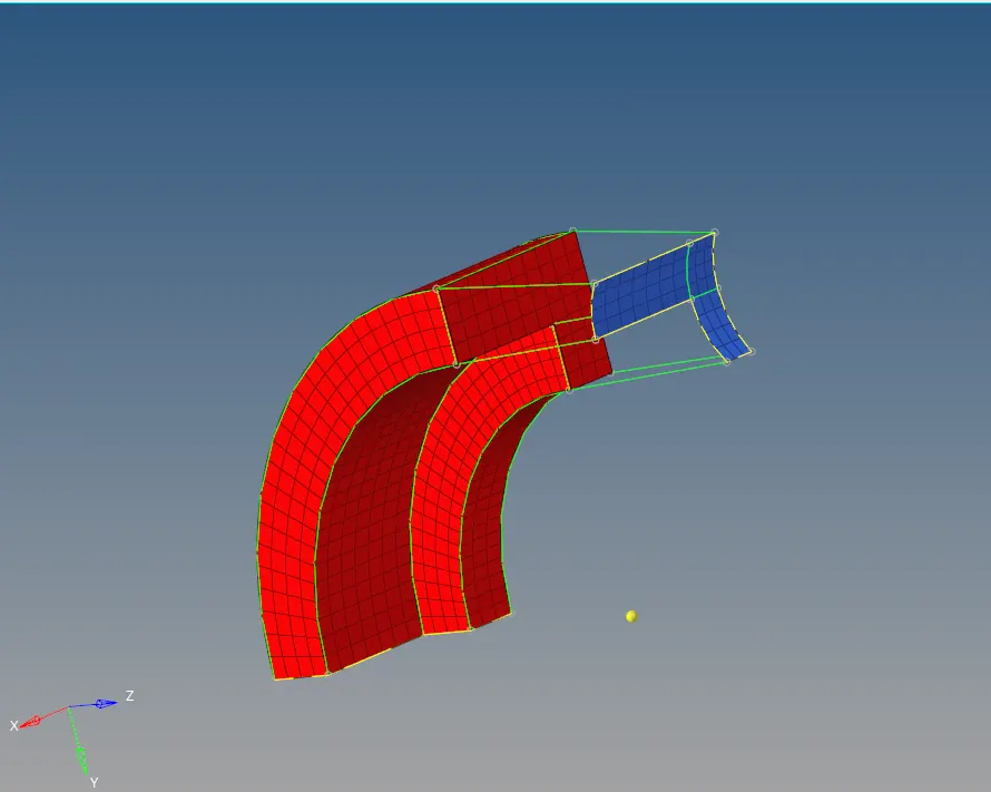
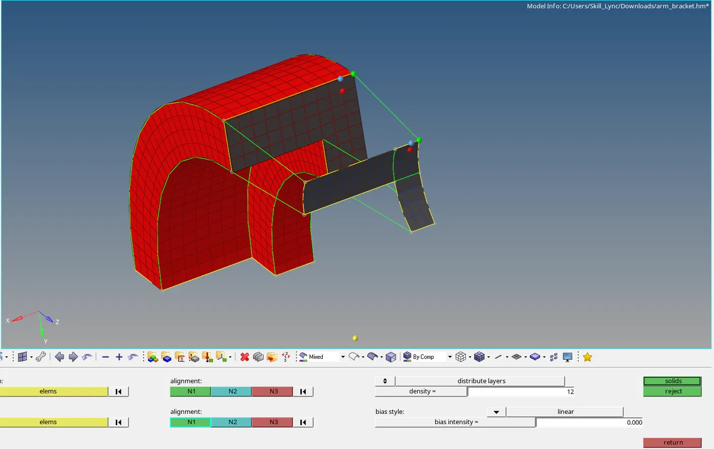
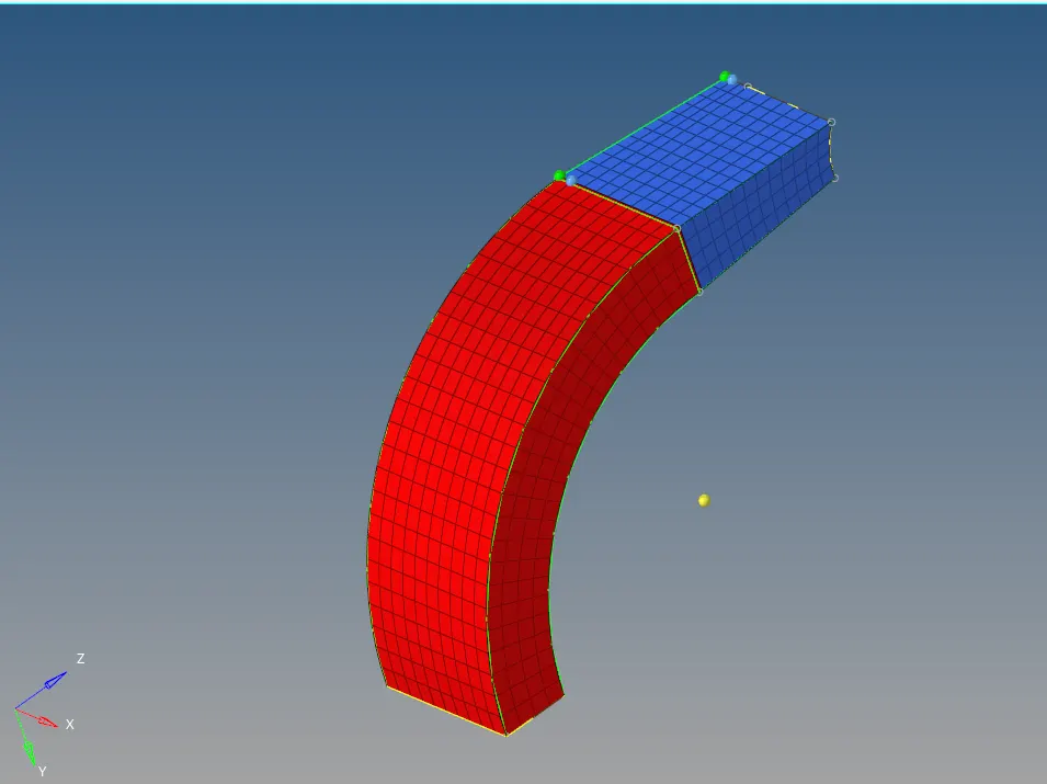
- For the part which is cylindrical, we need to make 3d and we need to make sure that the previous element needs to match.
- Then for the cylinder, we need to make a mesh on the top which must be quads
- After completion of mesh then go solid map and select general and set surface geometry as none
- Destination geometry as the bottom surface and give path as node otherwise they will not align
- If nodes are not present we need to project them
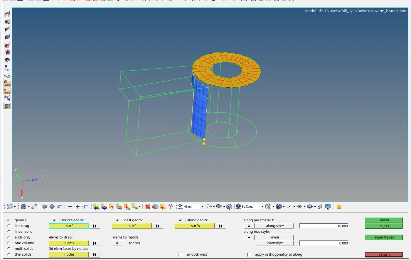
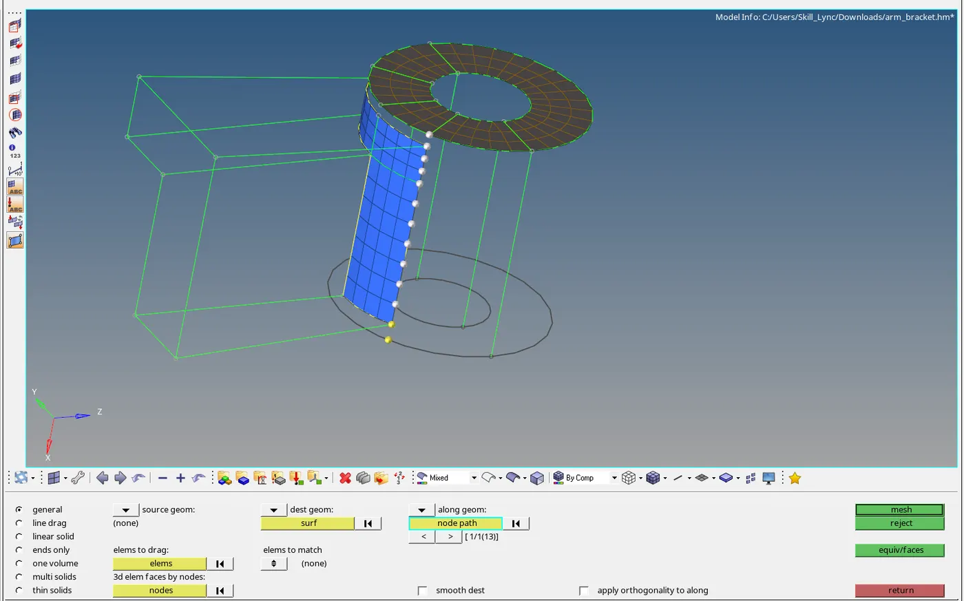
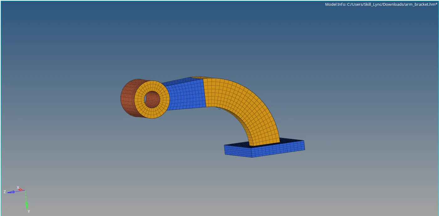
- Component mesh completed.
RADIOSS ANALYSIS:-
- Majorly this software is used for performing nonlinear analysis
1. Check the material properties of the rail component and calculate the speed of sound in steel rail=_______
Young’s Modulus = E =210000 g/mm^2
Density = ρ = 0.0078 g/mm^3
C = √E/√ ρ
C = √210000/√0.0078
C = 5188.74 mm/sec.
2. The length of the rail is about 1000 mm.calculate the time takes for a shock wave to travel from one end of the rail to the other
Length = L = 1000mm,
Speed = C = 5188.74 mm/sec
Δte = L/C = 1000/5188.74,
Δte = 0.19272 sec.
3.Time for sound to travel the length of rail=0.19272 sec
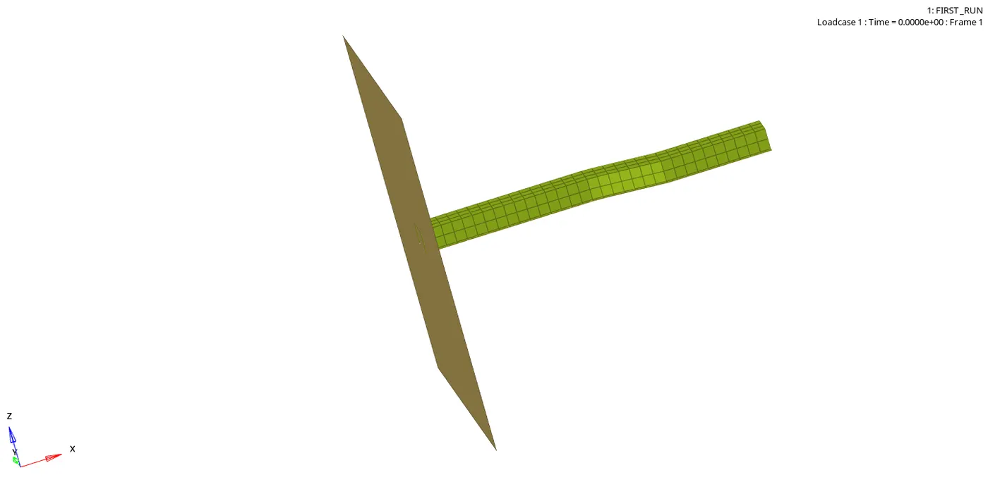
4.Edit the engine file so that the stress wave can be monitored, moving from one end of the rail to the other during an impact -this will require a termination time equal to the time it takes for the sound to travel the length of the rail(set on/RUN card)
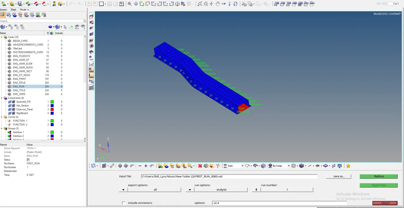
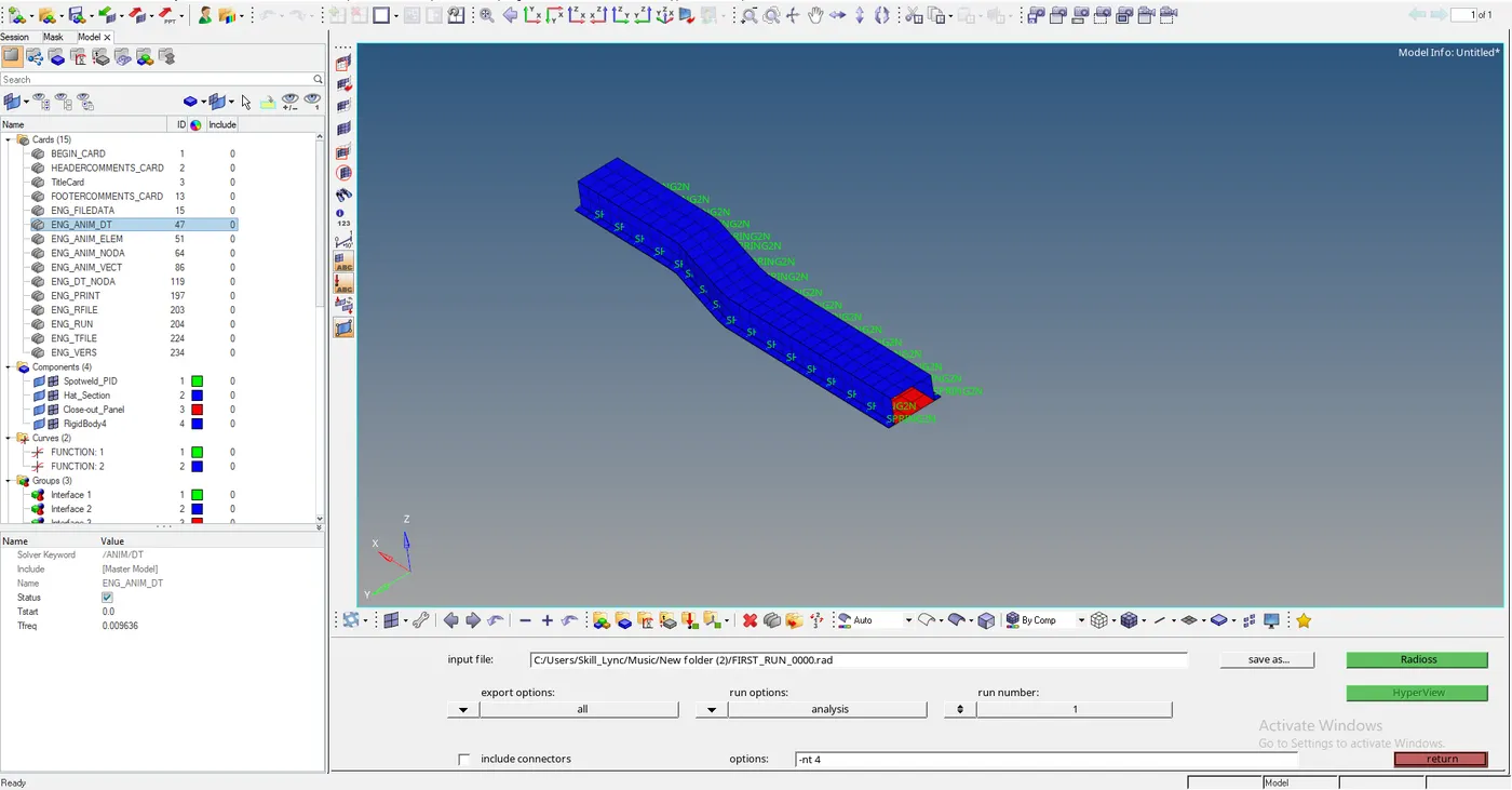
5. Set the frequency of animation output to a time that will give 20 animation steps(/ANIM/DT).
Ans,
Frequency of animation = f = 0.1927/20,
Frequency of animation = f = 0.009636 Hz.
6.Set the frequency of animation output to a time that will give 20 animation steps(/ANIM/DT)
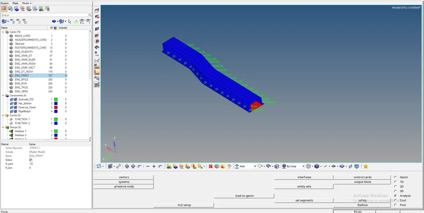
6.Change /print -10.
CONCLUSION:-
- I understood how to use tetra mesh
- I understood how to use Box mesh
- I understood how to calculate critical time and frequency