Assignment 1-2D Meshing Challenge
AIM:
To clean the geometry, extract the midsurface, clean the extracted midsurface, mesh the component and assign the thickness by creating a generic property using the given boundary conditions:
- Target element length: 5mm
- Minimum element size: 3.5mm
- Maximum element size: 7mm
GIVEN MODELS:
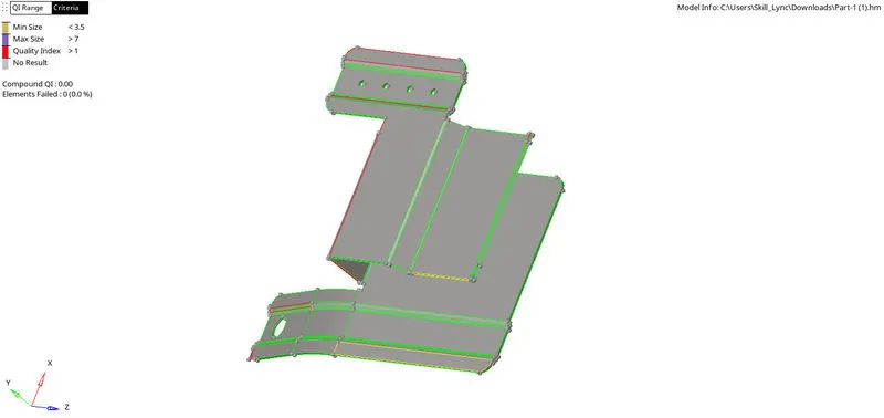
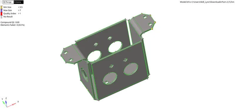
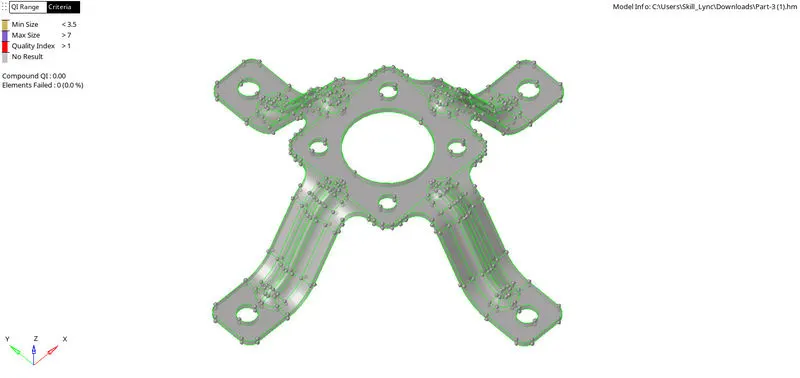
PROCEDURE:
STEP 1: OPENING THE FILE:
- The File given is in ‘.hm’ format. It can be opened directly by using the following the steps.
- In the Main Bar, Select File >> Click on Open >> Click on Model>> Select the File to be opened >> Click on Open.
- The file is opened. To view the Model (if the Screen is empty), Click ‘f’ on the keyboard to fit the model on the screen.
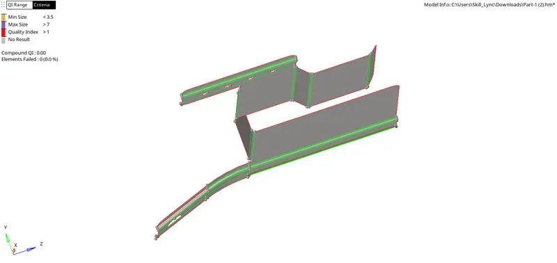
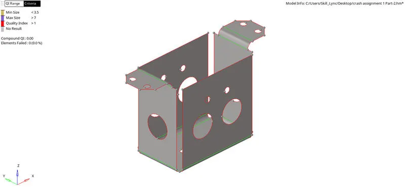
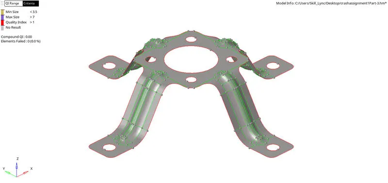
STEP 2: EXTRACTING THE MID SURFACE:
- Since the surfaces are having uniform thickness, we can use auto midsurface by using skin offset option.
- For auto midsurface, go to Geometry>Auto midsurface.
- Go to extraction option and choose skin offset option for better offset.
- Then go back to Auto extraction, select the parent surface body of which the midsurface has to be extracted, duplicate it to the current component and click on extract.
- Our midsurface is ready.
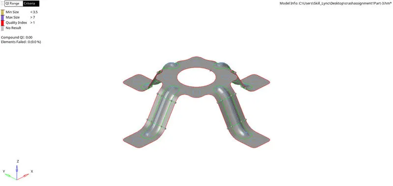
STEP 3: GEOMETRY CLEANUP:
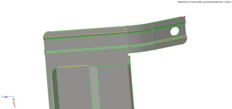
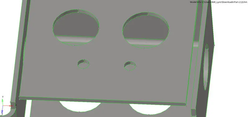
- After extracting the midsurface, we can check for deformations.
- Some surfaces are missing, these can be filled using filler surface tool.
- Some surfaces are having yellow lines which indicates that there are more than one surface.These extra surfaces can be deleted.
- Some surfaces are having holes less than 5mm.These holes can be filled using surface filler option from quick edit tool and the lines can be toggled away.
STEP 4: MESHING:
- After setting up the quality criteria as given for minimum and maximum lengths, we can start meshing.
- 2D>Automesh
- After clicking on the surface option, select the surfaces that need to be meshed.
- Assign the element size as 5mm.
- Give the mesh type as mixed.
- Element to surface component is selected to keep the mesh in surface component itself.
- Keep connectivity option is selected for better mesh connectivity and mesh flow.
- Align and size options are also marked for better mesh flow.
- Click on mesh.
- In case the mesh is not satisfactory, we can change the surface option to elements and conduct the mesh again.
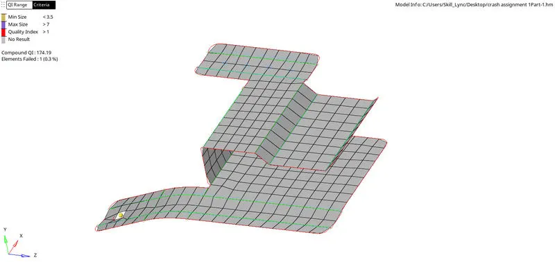
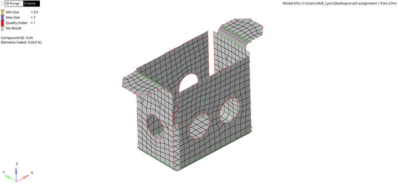
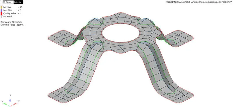
- The mesh we get will face a lot of trias and rotational quads.Also the mesh flow wont be that good.In this case, we can use the quality index option.
- This can be done by using 2d>quality index> cleanup tools.
- By using different options from cleanup tools. We can reduce the number of trias by using drag tria opton and can smooth the elements to increase the mesh flow.
STEP 5: TO CHECK NORMALS:
- To check for the normals, go to Tool>Normals.
- Choose elements.
- Select displayed 2d elements for selecting the whole elements.
- Color display in order for color representation.
- Click on display.
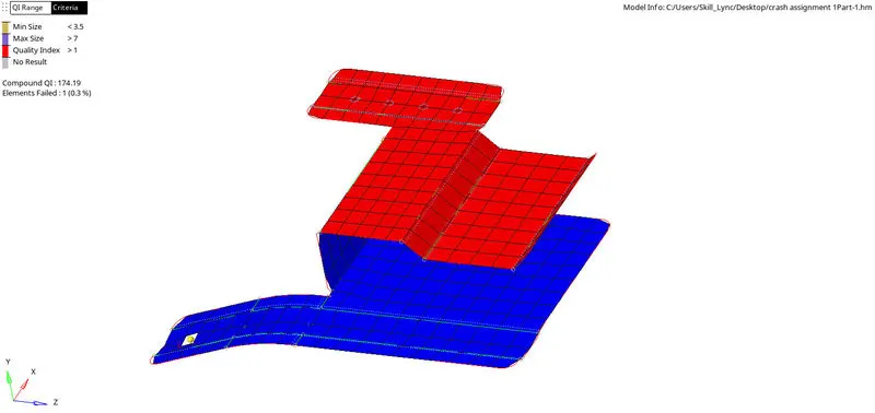
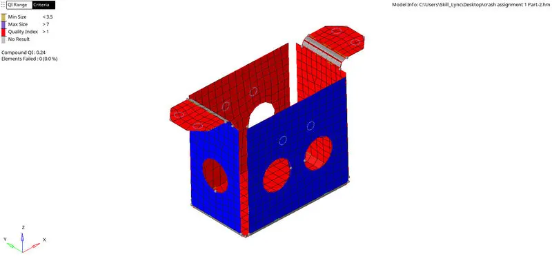
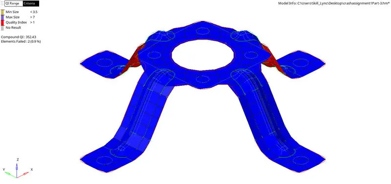
- The whole model will be represented in blue and red colors.
- If one side is having both the colors, then we have to correct the normals.
- By clicking on adjest, almost all of it will be corrected.
- If it doesnt get corrected, we can change the displayed 2d elements to elements and change accordingly.
- Click on reverse to change the normals.
STEP 5: TO CHECK FOR FREE EDGES:
- For checking normal we need to go to Tool> Edges.
- Choose Elements and select the whole elements.
- Click on Find edges.
- Now Hide other parts and Make edges mesh only visible.
- Now check if there is red line on any area which is not a boundary.
STEP 6: ASSIGNING THICKNESS:
- To make property. Right click on Model view area > Create> Property.
- Rename the property with the thickness value.
- Also set the thickness of the property. By clicking on property we can see its details below.
- In that we can see a T which represents the thickness give the thickness value . Click on enter.
- To Apply the property to the Components, Right click on component.
- Select assign. Choose the property of the component from the pop up dialogue box.
- Click on Apply. Click on Ok.
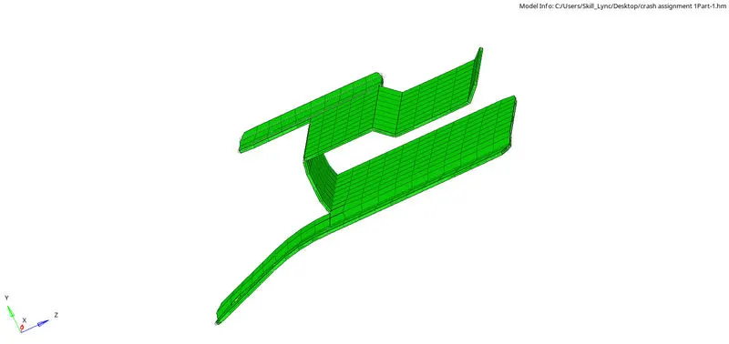
- To see the mesh in 3D. Choose the 2D detailed element representsation.
FINAL MODEL:
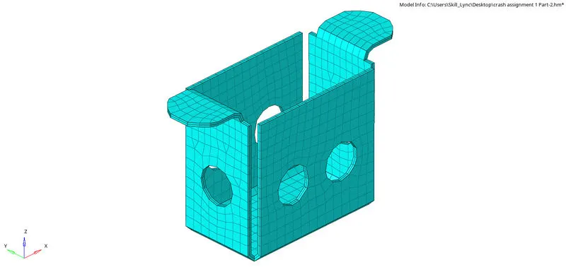
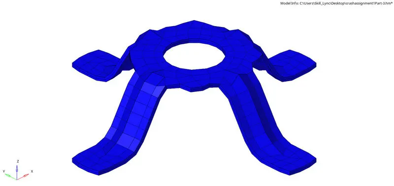
RESULT:
Finished the Mid surfacing and Meshing of the components with Zero error of quality criteria . Also checked the normal and free edge and applied the thickness to the components.