Assignment 1-2D Meshing Challenge
ASSIGNMENT 1 . 2D MESHING CHALLENGE
Overall objective:
The main overall objective of Assignment 1 is to cleanup the given .hm file model and extract the midsurface of the model and than geometric cleanup on the extracted surface and to mesh with the prescribed element size that is 5mm and min element length failure value is 3.5mm, max. element length failure value is 7mm after checking for element failures create a property and assign thickness for the elements.
Challenge 1 . Practise
Objective :
The main objective in challenge 1 is to perform geometrical cleanup on the given model and than extracting the midsrface than check for any errors in geometry and fix them and than 2D meshing on the Extracted model with given element sizes.
Target element size = 5mm
Min. element size = 3.5mm
Max. element size = 7mm
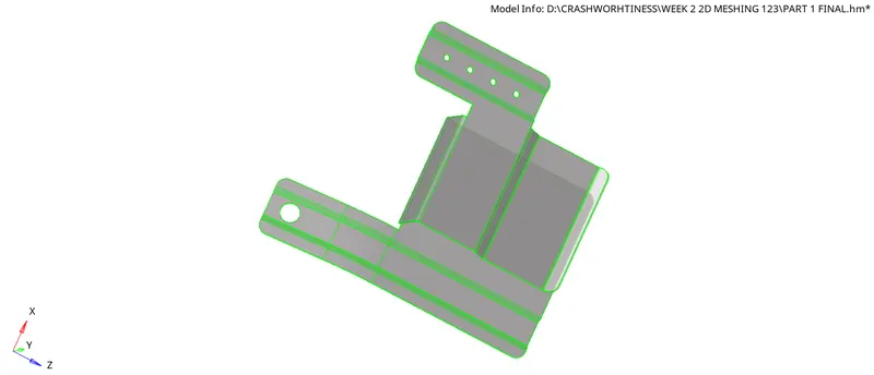
Procedure:
- First of all download the question file from the skill Lync website than
- Open file directly as it is in .hm format only
- Select Radioss as it can be sent to the solver afterwards by exporting directly
- Examine the whole model carefully and check that there are no free edges inside the geometry if any are present
- Use Filler surface or Toggle edge option from the quick edit panel(F11)
- Next go to criteria file settings and mention Target elem length as 5mm , Min. length = 3.5mm, Max. length = 7mm than click apply - ok
- Now go to Geometry - Midsurface - Closed solid - Select the surface displayed - extract directly through Auto midsurface as the total thickness is constant -Extract
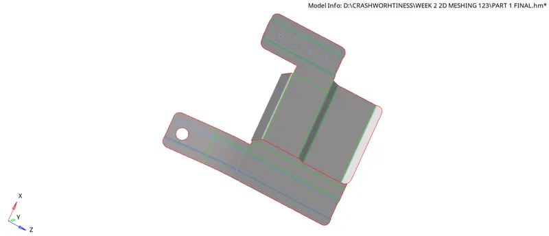
- After extracting Fit the model 'F' on the gaphical area than check for any free edges or any defeaturing and toggle the surfaces where it is below men.length and check for connections if any missing connect those properly
- Here as the keyword given in question that holes with 5mm or below 5 mm can be ignored try to remove those by primarily -
- Checking the radius by going to Geometry - Distance(F4) - Three nodes - Clck & hold left click on the hole edge and after line is highlighted select three nodes on the edge of hole by which radius of the hole can be known - if the radius is above 2.5mm keep those if not ignore by -
- Going to Geo - Quick edit (F11) - use Filler surface to fill the hole gap and than by usin Toggle edge option suppress the outer lines of hole circles than it will also become a flat surface by removing the hole.
- Than go to 2d - Automesh - select element size = 5mm - start selecting individual surfaces - Click on Mesh -Like this select surfaces one after the other and mesh the model
- Always check the quality criteria of the elements and check how many elements are failing by going to Tool - Check elements - check by clicking on the specified criteria names and in the lower left corner the failed elemnets count will be shown
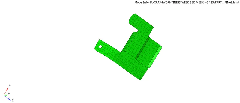
- If any elements are failing than go to 2d - Remesh by using automesh or
- Go to 2d - Quality Index(Q) - than by using element optimise, Drag trias , swap edge options try to remove the failing elements and check elements again and bring he failed values to null or 0.
- Than check for edges and Elements connectivity by going to Tool - Edges - Select elements - if any free edges -delete them and check for equivalence by this if any element connectivity is missing it can be resolved
- Finally after checking for all elements and connections of model Go to 2d - smooth - select iterations - Hit smooth - By this the mesh will be set properly and if any fine corrections needed will be done on mesh by which mesh flow will be proper
- After this create a new component with name according to the thickness of the model and mention the thickness values in the dropdown and also create a property with same thickness values and assign the component with this property
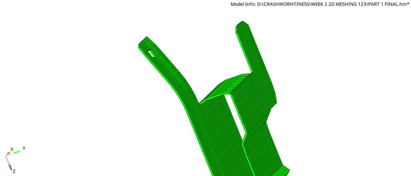
- Now go to Tool - organise - Elements - select which elements to be moved and select the destination component file name than click on Move by doing this the elemnents will be assigned with the given thickness
- It can be checked by going to 2D detailed elemnent representation by which the elements can be seen with the thickness size given.
- Save the model in the required file location in the computer in .hm format and attach the files to the challenge submission files.
Conclusion:
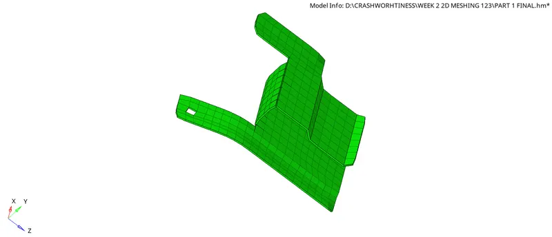
After performing these operations one after the other in following sequence on the given model we can achieve a good and precise model with required mesh size that is 5mm and fine quality of mesh which will also help a solver for its next process.
Challenge 2 . Clip Repair
Objective :
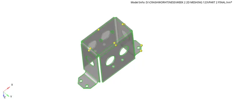
The main objective in challenge 2 is to perform geometrical cleanup on the given model and than extracting the midsrface than check for any errors in geometry and fix them and than 2D meshing on the Extracted model with given element sizes.
Target element size = 5mm
Min. element size = 3.5mm
Max. element size = 7mm
Procedure:
- First of all download the question file from the skill Lync website than
- Open file directly as it is in .hm format only
- Select Radioss as it can be sent to the solver afterwards by exporting directly
- Examine the whole model carefully and check that there are no free edges inside the geometry if any are present
- Use Filler surface or Toggle edge option from the quick edit panel(F11)
- Next go to criteria file settings and mention Target elem length as 5mm , Min. length = 3.5mm, Max. length = 7mm than click apply - ok
- Now go to Geometry - Midsurface - Closed solid - Select the surface displayed - extract directly through Auto midsurface as the total thickness is constant -Extract
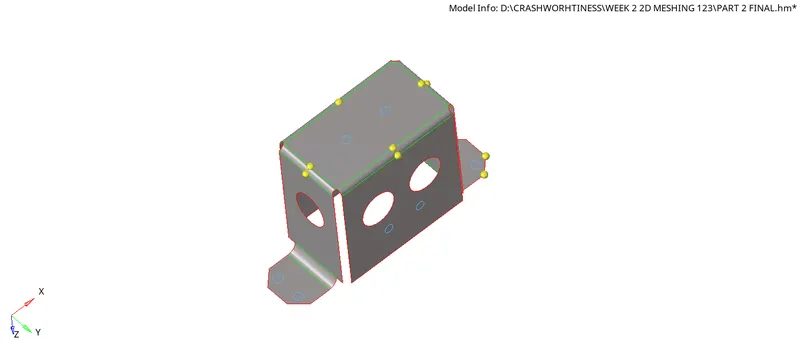
- After extracting Fit the model 'F' on the gaphical area than check for any free edges or any defeaturing and toggle the surfaces where it is below men.length and check for connections if any missing connect those properly
- Here as the keyword given in question that holes with 5mm or below 5 mm can be ignored try to remove those by primarily -
- Checking the radius by going to Geometry - Distance(F4) - Three nodes - Clck & hold left click on the hole edge and after line is highlighted select three nodes on the edge of hole by which radius of the hole can be known - if the radius is above 2.5mm keep those if not ignore by -
- Going to Geo - Quick edit (F11) - use Filler surface to fill the hole gap and than by usin Toggle edge option suppress the outer lines of hole circles than it will also become a flat surface by removing the hole.
- Than go to 2d - Automesh - select element size = 5mm - start selecting individual surfaces - Click on Mesh -Like this select surfaces one after the other and mesh the model
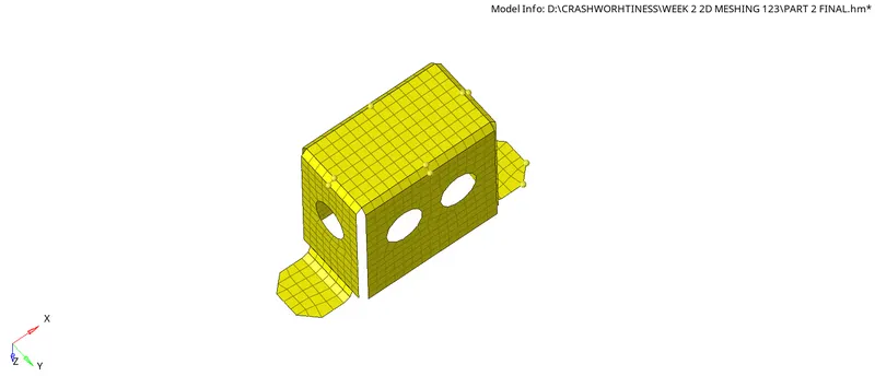
- Always check the quality criteria of the elements and check how many elements are failing by going to Tool - Check elements - check by clicking on the specified criteria names and in the lower left corner the failed elemnets count will be shown
- If any elements are failing than go to 2d - Remesh by using automesh or
- Go to 2d - Quality Index(Q) - than by using element optimise, Drag trias , swap edge options try to remove the failing elements and check elements again and bring he failed values to null or 0.
- Than check for edges and Elements connectivity by going to Tool - Edges - Select elements - if any free edges -delete them and check for equivalence by this if any element connectivity is missing it can be resolved
- Finally after checking for all elements and connections of model Go to 2d - smooth - select iterations - Hit smooth - By this the mesh will be set properly and if any fine corrections needed will be done on mesh by which mesh flow will be proper
- After this create a new component with name according to the thickness of the model and mention the thickness values in the dropdown and also create a property with same thickness values and assign the component with this property
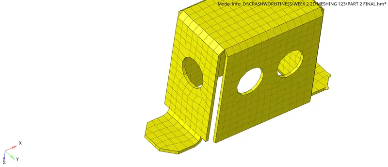
- Now go to Tool - organise - Elements - select which elements to be moved and select the destination component file name than click on Move by doing this the elemnents will be assigned with the given thickness
- It can be checked by going to 2D detailed elemnent representation by which the elements can be seen with the thickness size given.
- Save the model in the required file location in the computer in .hm format and attach the files to the challenge submission files.
Conclusion:
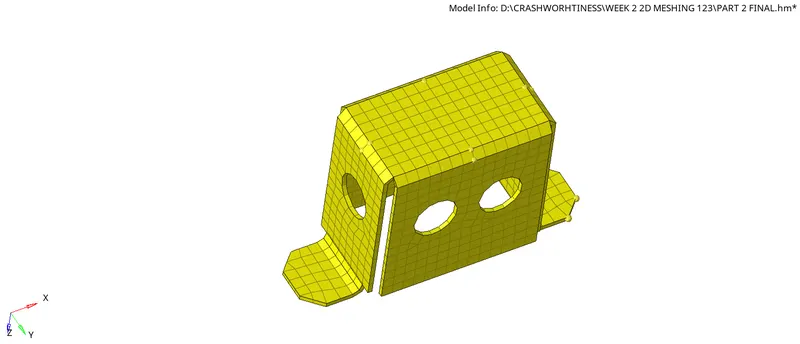
After performing these operations one after the other in following sequence on the given model we can achieve a good and precise model with required mesh size that is 5mm and fine quality of mesh which will also help a solver for its next process.
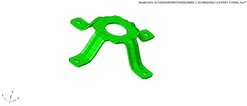
Challenge 3 . Mounting Bracket
Objective :
The main objective in challenge 3 is to perform geometrical cleanup on the given model and than extracting the midsrface than check for any errors in geometry and fix them and than 2D meshing on the Extracted model with given element sizes.
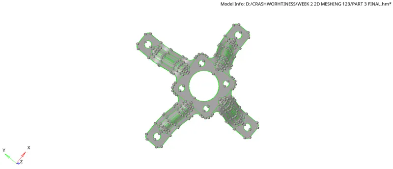
Target element size = 5mm
Min. element size = 3.5mm
Max. element size = 7mm
Procedure:
- First of all download the question file from the skill Lync website than
- Open file directly as it is in .hm format only
- Select Radioss as it can be sent to the solver afterwards by exporting directly
- Examine the whole model carefully and check that there are no free edges inside the geometry if any are present
- Use Filler surface or Toggle edge option from the quick edit panel(F11)
- Next go to criteria file settings and mention Target elem length as 5mm , Min. length = 3.5mm, Max. length = 7mm than click apply - ok
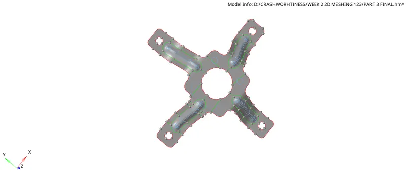
- Now go to Geometry - Midsurface - Closed solid - Select the surface displayed - extract directly through Auto midsurface as the total thickness is constant -Extract
- After extracting Fit the model 'F' on the gaphical area than check for any free edges or any defeaturing and toggle the surfaces where it is below men.length and check for connections if any missing connect those properly
- Here as the keyword given in question that holes with 5mm or below 5 mm can be ignored try to remove those by primarily -
- Checking the radius by going to Geometry - Distance(F4) - Three nodes - Clck & hold left click on the hole edge and after line is highlighted select three nodes on the edge of hole by which radius of the hole can be known - if the radius is above 2.5mm keep those if not ignore by -
- Going to Geo - Quick edit (F11) - use Filler surface to fill the hole gap and than by usin Toggle edge option suppress the outer lines of hole circles than it will also become a flat surface by removing the hole.
- Than go to 2d - Automesh - select element size = 5mm - start selecting individual surfaces - Click on Mesh -Like this select surfaces one after the other and mesh the model
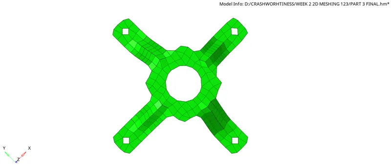
- Always check the quality criteria of the elements and check how many elements are failing by going to Tool - Check elements - check by clicking on the specified criteria names and in the lower left corner the failed elemnets count will be shown
- If any elements are failing than go to 2d - Remesh by using automesh or
- Go to 2d - Quality Index(Q) - than by using element optimise, Drag trias , swap edge options try to remove the failing elements and check elements again and bring he failed values to null or 0.
- Than check for edges and Elements connectivity by going to Tool - Edges - Select elements - if any free edges -delete them and check for equivalence by this if any element connectivity is missing it can be resolved
- After checking for all elements and connections of model Go to 2d - smooth - select iterations - Hit smooth - By this the mesh will be set properly and if any fine corrections needed will be done on mesh by which mesh flow will be proper
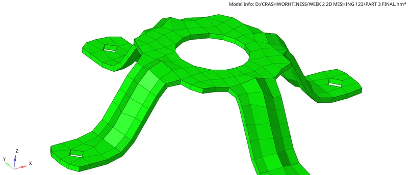
- After this create a new component with name according to the thickness of the model and mention the thickness values in the dropdown and also create a property with same thickness values and assign the component with this property
- Now go to Tool - organise - Elements - select which elements to be moved and select the destination component file name than click on Move by doing this the elemnents will be assigned with the given thickness
- It can be checked by going to 2D detailed elemnent representation by which the elements can be seen with the thickness size given.
- Save the model in the required file location in the computer in .hm format and attach the files to the challenge submission files.
Conclusion:
After performing these operations one after the other in following sequence on the given model we can achieve a good and precise model with required mesh size that is 5mm and fine quality of mesh which will also help a solver for its next process.