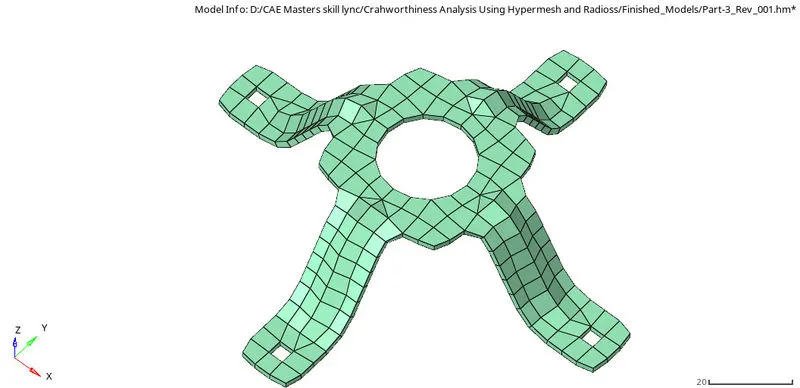
Meshing of components using Hypermesh
MESHING OF COMPONENTS USING HYPERMESH
OBJECTIVE:
- The objective is to perform geometry cleanup for the given components (i;e Practice model, Clip repair and Mounting bracket) and to mesh the same by extracting mid surface.
- Assign the properties and Thickness for the 2D mesh elements.
PROCEDURE:
1. Import the given components to Hypermesh and change the color mode to By Topo to view the geometry properly. Delete solids if any.
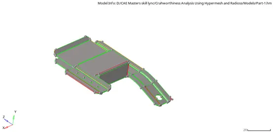
Fig: Imported model (Practice model)
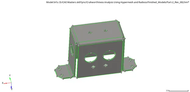
Fig: Imported model (Clip repair)
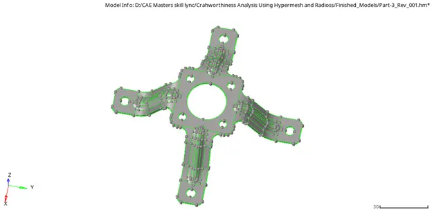
Fig: Imported model (Mounting Bracket)
2. The parent surface has some of the issues like free edges, surface openings, duplicate and overlapped surfaces as shown in figure. These must be cleared using toggling the edges and using replace point options and duplicate surfaces must be deleted. Ensure that all the edges were in green color.
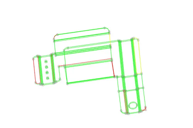
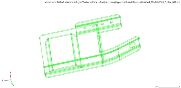
Fig: Before and After geometry cleanup
3. The mid surface must be extracted automatically using skin offset method. The extracted mid surface is shown in figure. Since the surface has some of the features which is falling below the minimum element length, which should be de-featured as shown below. To measure the distance use distance option.
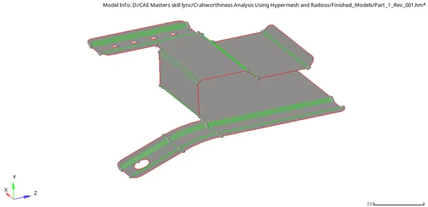
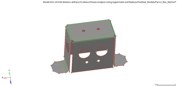
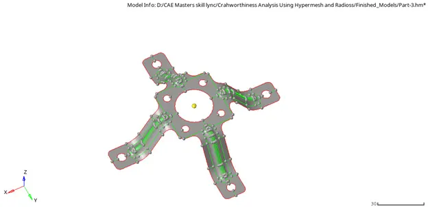
Fig: Extracted Mid surfaces
4. In the practice model the fillet length was below minimum and hole diameter was below 5mm, so of the line in the fillet was toggled and holes were filled and edges were toggled as shown.
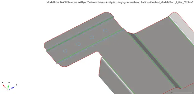
Fig: Filling of holes
5. The lines near to the hole were too close and the gap was below the minimum hence the lines were toggled.
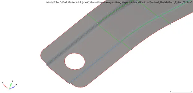
Fig: Defeatuing of fillets.
6. In the clip repair model, even though the holes are of diameter 5mm because of dimensional constraint those were filled and edges were toggled as shown. The component had small edges which are created between 2 lines. A center point is introduced and the lines were replaced to the introduced point as shown.
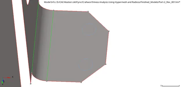
Fig: Filling of holes
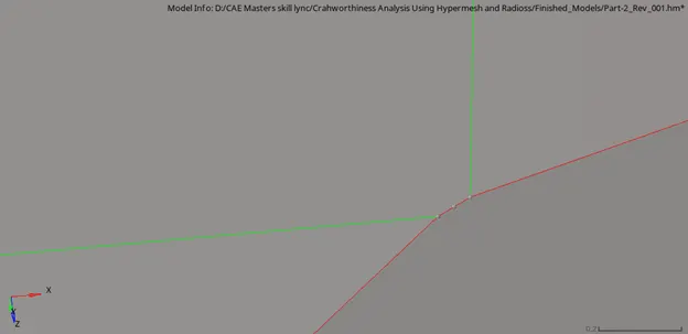
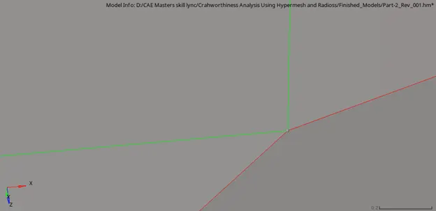
Fig: Before and After replacing
7. The mounting bracket is symmetric about its X and Y axis so the component was split in to ¼ so that we can reflect the same. The stamped slot has some of the lines falling below its minimum which all are toggled as shown. The holes were filled to avoid the elemental failures.
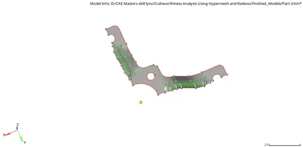
Fig: Splitted Mid surface
8. Before starting the meshing the quality criteria must be entered in the criteria file setting. Since the target, Min. and Max. Element length was prescribed and rest of the criteria was assumed as shown below.
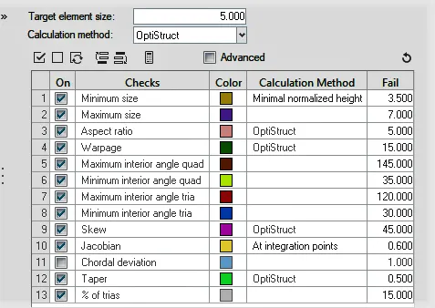
Fig: Quality criteria
9. While meshing near to the hole the elements of the edge must be rotated such that they are parallel to the nearest feature line.
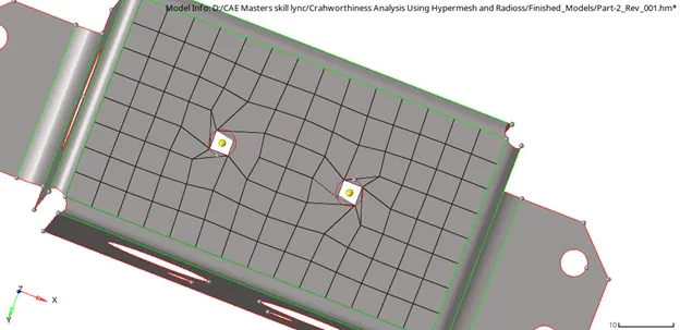
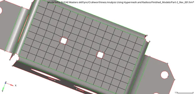
Fig: Before and After rotating
10. In the clip repair model the elements can be positioned to the other side by duplicating the elements. Since the mounting bracket component is symmetric the ¼ of the geometry is meshed and then reflected to X and Y axis respectively.
11. After completion of the meshing assign the thickness and material for the mesh. Check for free edges, duplicates and normals for the mesh if any clear them.
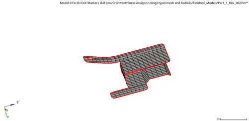
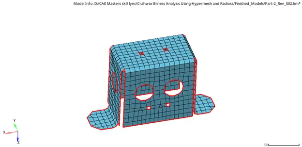
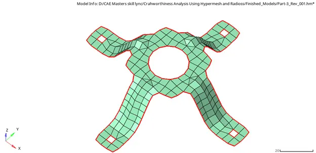
Fig: Free edge checking
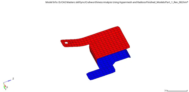
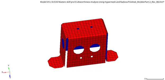
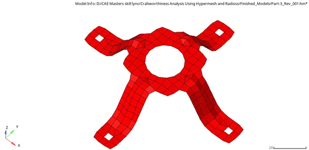
Fig: Checking normals
CONCLUSION:
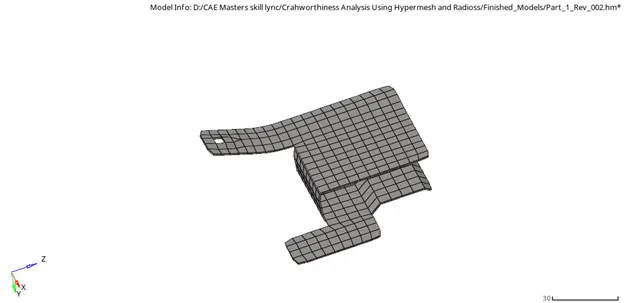
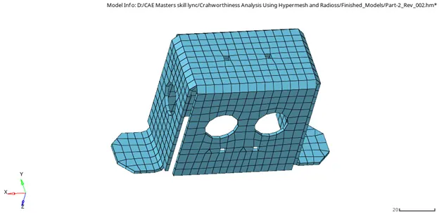
The given components were meshed according to the given criteria and the following results were obtained.
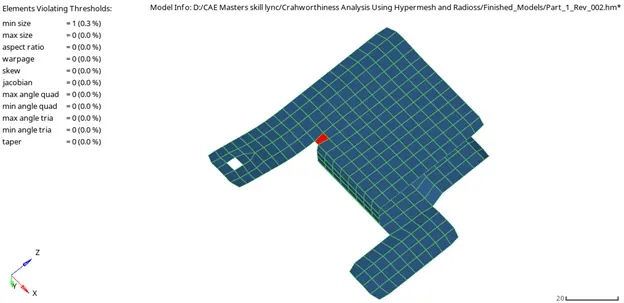
1. One element was failed for the minimum element length due to the feature constraint in the practice model.
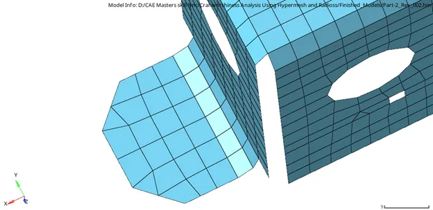
2. The clip repair component has 2 Tria element at the free edge on both the side of the clip as shown.
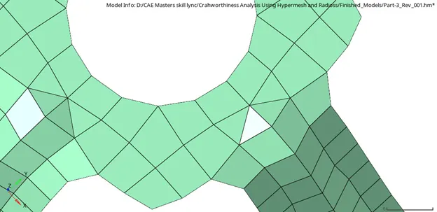
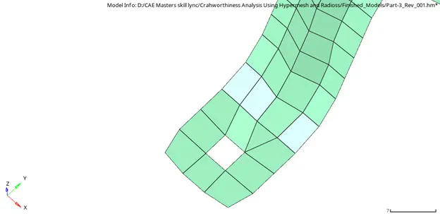
3. The mounting bracket has trias touching each other which is difficult to avoid and a tria element sharing node to the hole edge.
FINAL MODEL:
Practice model
Clip Repair
Mounting Bracket