Assignment 1-2D Meshing Challenge
OBJECTIVE:
To mesh the given components as per the given criteria after geometry cleanup and midsurfacing. The three components are,
- Practice Component
- Clip Repair
- Mounting Bracket
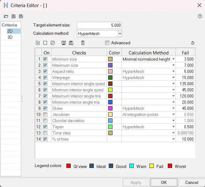
The 2D mesh is to have a target length of 5 mm with a minimum of 3.5 mm and a maximum of 7 mm. The thickness will also need to be assigned after meshing.
IMAGES OF MODELS:
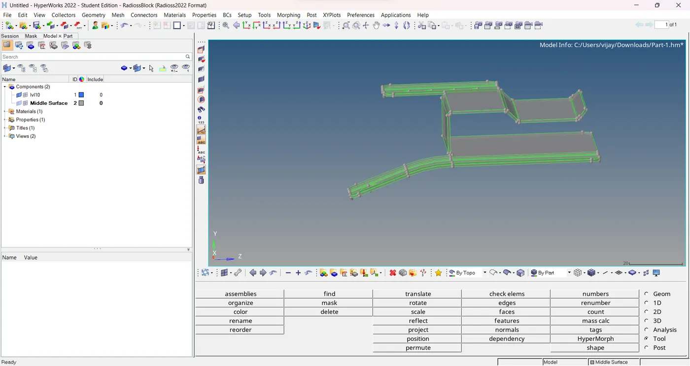
practice model_1
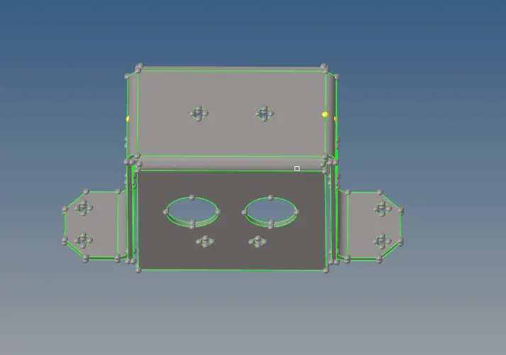
Practice model_2:
PROCEDURE:
- The models are imported to Hypermesh with the RADIOSS solver active.
- We switch to topo mode to check to see if there are solids - they are to be deleted if any exist.
- These models did not have solids.
- But there definitely is some geometry cleanup required, considering the number of free edges (red lines).
- Geometry cleanup is carried out first. To ensure the models are closed solids (for using the auto-midsurface tool later), we need to make sure there are no imperfections.
-
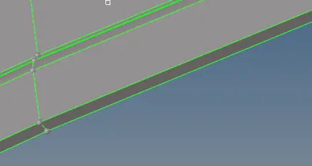
For example, in the below case, we can see multiple free edges (red lines). This is because there is no connectivity between this surface and the adjacent one.
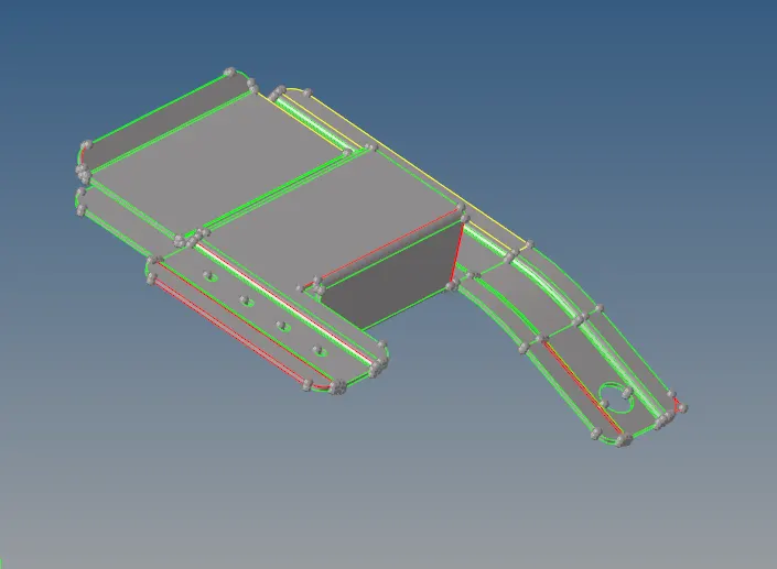
- To fix this, we simply need to toggle the line.
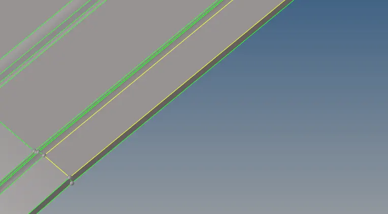
- The toggle tool can be accessed from the quick edit section in the geometry panel.
- The tolerance should be adjusted accordingly.
- The higher the tolerance, the higher the range of adjacent edge detection for the algorithm.

- Another case of geometry cleanup that was encountered in this assignment was fixing missing surfaces.
- This is fixed by using the filler surface tool from the same quick edit section.
- We simply need to select one of the free edges for the algorithm to detect and create a surface using the free edges available.
- After the models were removed of imperfections,
- we can go ahead with midsurfacing.
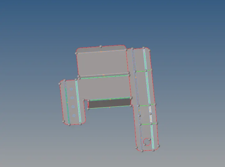
- This can be either done using the offset tool (Geometry > Surface Edit > Offset) or through the auto-midsurface tool (Geometry > Midsurface). I went for the auto-midsurface tool for a couple of them.
- The algorithm detects the thickness and creates a midsurface (if it is a closed solid).
- For the mounting bracket, I used the manual offset method.
- First, we need to create a new component in the component tree (right-click > create > component) and let's name it 'Middle Surface'.
-
The offset value is half the thickness of the bracket.
-
We can select any one face from any one of the faces.
-
And then, right-click surfaces and select 'by face'. When this is done, the entire face is selected. Not the entire component.
- Before carrying out this step, we need to ensure that the newly created 'Middle Surface' component is our current component. After confirming, we can select 'duplicate' by selecting surfaces again. And now, we can select 'current component'. The offset of the component is now transferred to our newly created component. But we are yet to offset the face.
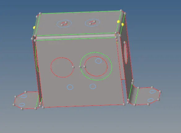
- Before selecting the offset button, we can verify the upcoming offset's normal, which could be in the opposite direction.
- If so, we can use the 'reverse normal' option to reorient it in the opposite direction. And then we can click offset.
- We now have our midsurface generated onto the newly created component.
- After midsurfaces are generated for all the components, all that's left before meshing is to prepare the geometry for the mesh, ergo, we need to prevent all possible element failures, primarily due to minimum length restrictions.
- We can toggle (quick edit > toggle) feature lines that may result in minimum length failures. That being said, it must be noted that we must avoid toggling lines at the cost of feature capturing as much as possible. But in cases as follows, they have to be toggled to ensure the mesh doesn't fail.
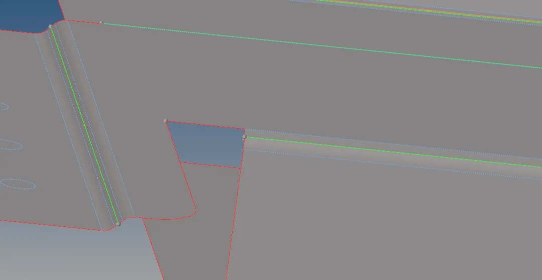
- In other cases, we can do the opposite and make cuts ourselves to ensure proper mesh flow and feature capturing. In this case, instead of two feature lines, we can use a midline to represent it. The mesh will still capture the feature pretty well. We can make use of the 'add point on line' tool to first create the points and then the split-surface node, split-surface line tools to make the cuts (all present in the quick edit section).
- After preparing the surfaces for meshing, we can assign the quality criteria for the meshing. This is done via Preferences > Criteria File Settings. The values can then be entered as per our requirements. Our focuses are the target, minimum and maximum lengths.
- Now we can start meshing each of the components. This is done using the automesh tool from the 2D panel. The surface to be mesh is selected, element size is specified (5 mm) and we can ensure mesh flow align and size options are checked. Mesh type will be mixed.

- We must start meshing from a certain region and work our way from that region (preferably one with more free edges). In more complicated models, we can make use of cut lines (quick edit > split surface node) to split the surface into smaller surfaces for better mesh control.
-
We will now check for equivalency by going to the edges section in the tools menu and previewing equivalence for varying tolerances (ranging between 0.2 mm to 2 mm). This is to ensure there are no misaligned elements or free edges, which we can also check using a different option in the same section. The preview equivalence option shows us the nodes that require equivalencing. They are rectified by clicking the 'equivalence' option in the menu. If some nodes haven't been tended to, it may require manual fixing, using the replace node option (F3).
-
After equivalencing, we can check for duplicates through the check elements tool in the same menu. If duplicates exist, we can click 'save failed', move on to the tool menu, select the 'delete' tool, select elements, right-click the element and select retrieve and then click the delete button. This should handle the duplicates.
-
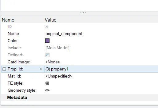
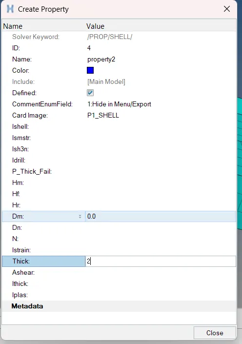
Finally, we can assign a thickness for each of our midsurfaces. We can do this by right-clicking and creating a component in the component tree. After a property is created, we can go to its section in the bottom left and scroll down to assign the aforementioned thickness. Then we can assign the thickness by selecting the midsurface, going to its properties box on the bottom left and assigning a prop_id, by selecting the thickness property. Similarly, we can assign the material as well through the same process.
NOTE:
For the following region, trias are touching each other (and another touching a hole). This, unfortunately, could not be avoided due to the feature. To ensure there were no warpage issues, the quads had to be split into two trias.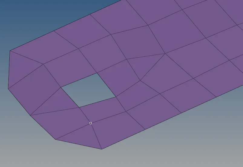
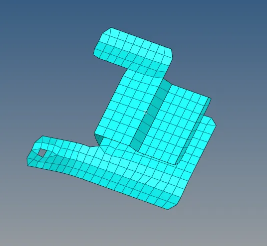
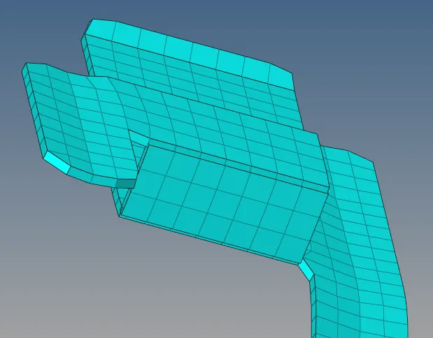
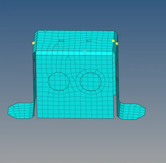
FINAL MODEL IMAGES:
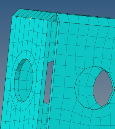
CONCLUSION:
- The given models were refined, midsurfaced and meshed as per the given requirements. In addition to that, good mesh quality & flow was upheld as much as possible and the generated mesh was assigned a thickness according to that of the parent geometry.