2D Meshing using Hypermesh
OBJECTIVE
- To free the parent geometry from all geometrical errors.
- To obtain the mid-surface of the parent geometry.
- To assign the material and geometrical property to the mid-surface.
- To set the required quality of the elements.
- To mesh the mid-surface with given quality criteria.
- To check for any discrepancy found in the FE (finite element) model and correct it, if any of it found.
- To check for failed elements and correct them.
PROCEDURE
FEM work was to work on three different parts, as shown in the figures below. Part 1 was having many surface errors, thus before stepping ahead with obtaining the midsurface, it was required to clean the geometry. However, it was not the case for the other two parts. Part 2 and part 3 were already clean with their parent geometry.
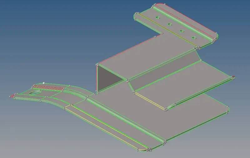
Figure 1: Part 1.
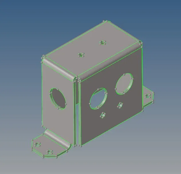
Figure 2: Part 2.
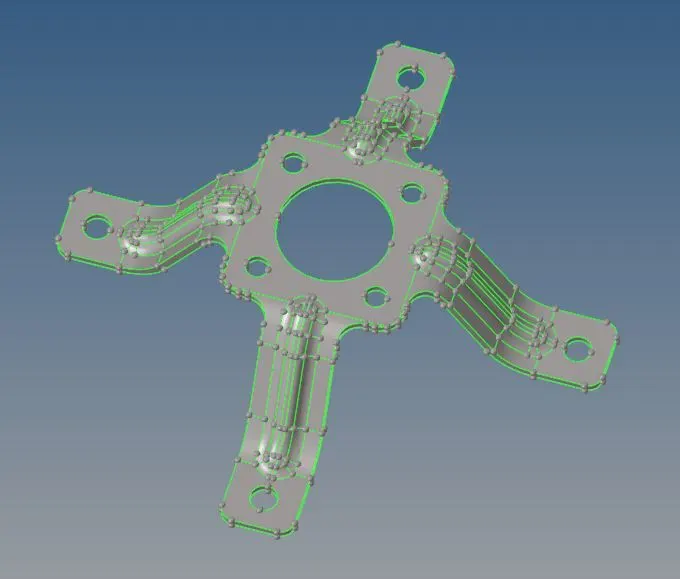
Figure 3: Part 3.
Geometry Clean-up on Part 1
The primary stage of meshing any part is its geometry clean-up. The part created in any modeling software when opened in another, because of change in the format of the file some errors occur in the geometry. This might include over-constrained lines, under-constrained lines, missing faces or duplicate faces, etc. A single part is comprised of so many faces. Each face is connected with other neighboring faces, the connection is represented by the green line and if the face is not sharing its edge then it is represented by a red-line which is also a free edge of that particular face. Ideally, in parent geometry, there should be the presence of only green lines and no red and yellow lines.
The line can also be suppressed if no division between faces is required. Fig. 4 shows the presence of these three kinds of lines.
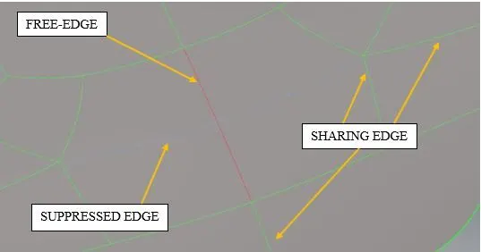
Figure 4: Different kinds of edges.
To free the edge, or connect, or suppress, there is an option called the ‘toggle edge’ in the Geom→quick edit. It can also be used from the Geom→edge edit→toggle. Fig. 5 shows the presence of a free edge in red color. It was because one face is over-extended than required.
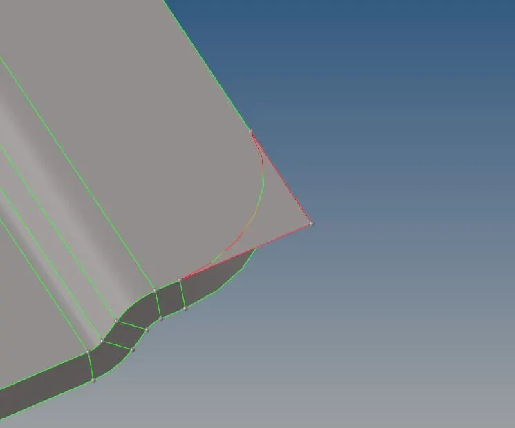
Figure 5: Presence of free-edge due to the presence of an over-extended face.
To correct it, one face was trimmed using the edge of its neighboring face on which it is lying, using Geom → surface edit → trim with surfs/plane → with surfs. Fig. 6 shows the correction in the face, however, the free-edges are still there.
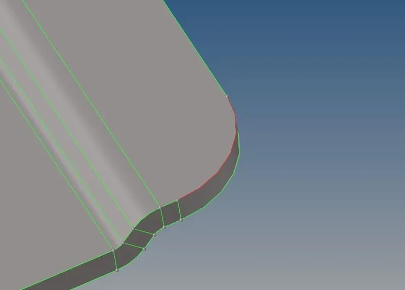
Figure 6: Presence of two faces, not sharing the edges.
Now, to correct such errors, Geom → quick edit → toggle, can be used. Fig. 7 shows the completely corrected face.
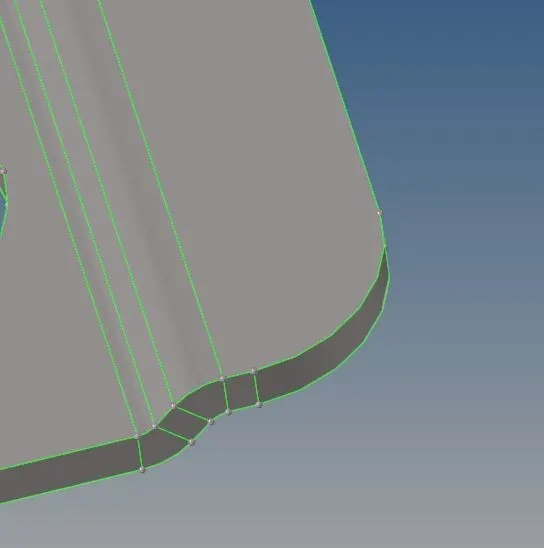
Figure 7: Completely corrected face.
When the face shares its edge with more than one face, it is represented by the yellow line, as shown in fig. 8.
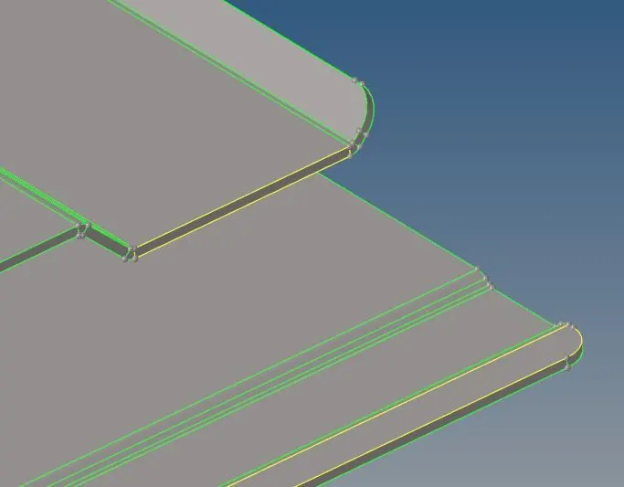
Figure 8: Presence of yellow line because of sharing the edge with more than one face.
When observed, it was found that it was there due to the presence of a duplicate face. When deleted one face, it automatically corrected itself. Fig. 9 shows the corrected geometry.
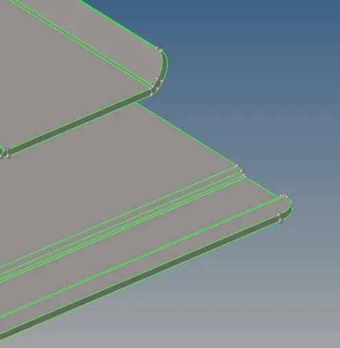
Figure 9: Elimination of yellow line error.
Fig. 10 shows the presence of a free edge due to the absence of a face.
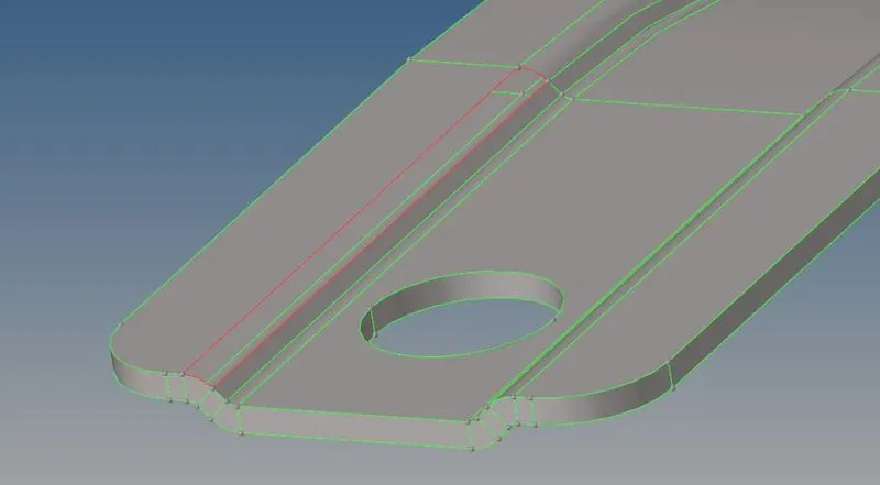
Figure 10: Presence of free-edge due to the absence of a face.
It was corrected using Geom → quick edit → filler surf, which automatically filled the missing surface. Fig. 11 shows the corrected geometry.
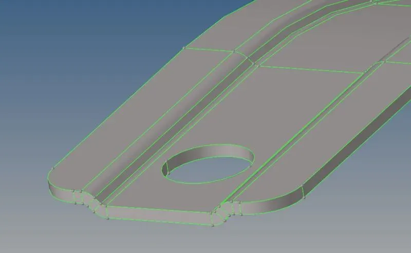
Figure 11: Elimination of free-edge error.
In part 2 and part 3, no geometry cleanup was required.
Obtaining the Mid-surface
After cleaning the geometry, the next stage of the procedure is to obtain the mid-surface of the complete part. Mid-surface is the neutral surface of the sheet metal part which has no thickness. A property is assigned separately to that mid-surface which defines its thickness. The reason behind extracting the mid-surface is when a thickness is assigned to the surface, half of the thickness gets applied on both sides of the mid-surface. Moreover, shell mesh is preferred because it reduces computational time. 3-d elements take more computational time to solve the problem compare to 2-d elements, because of the increase in the number of nodes. For the components with uniform and 5-6 mm thickness, generally, 2-d elements are preferred. To obtain the mid-surface, Geom → midsurface is the tool that can be used. The figures below show the mid-surface of all three parts.
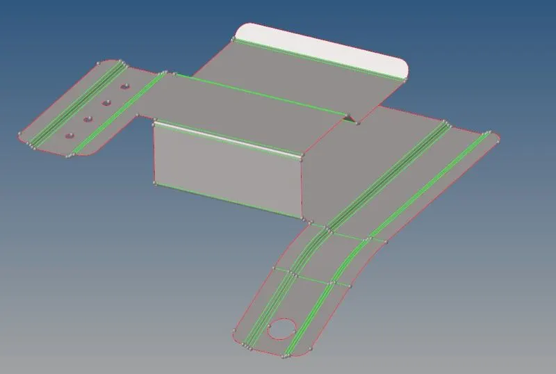
Figure 12: Mid-surface of part 1.
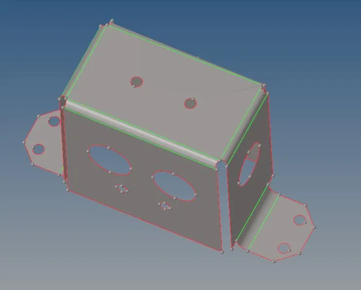
Figure 13: Mid-surface of part 2.
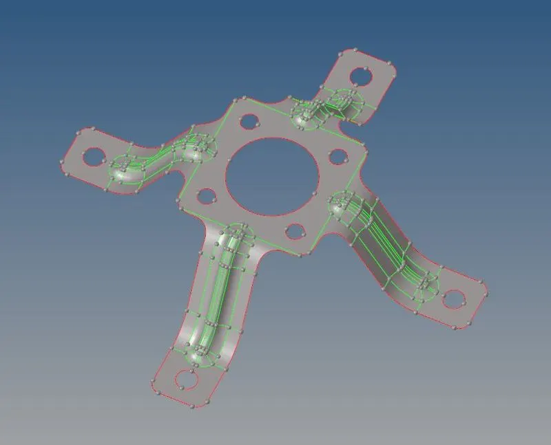
Figure 14: Mid-surface of part 3.
Assigning Material Property and Thickness
To assign a material to all the three mid-surfaces, a material card was created by right-clicking in the tab, then Create → Material. To that material card, properties of steel material were provided, and that card was assigned to the mid-surface component.
Similarly, the property card was created, to which the thickness was provided and the card was assigned to the mid-surface component.
Setting Quality Criteria
2d meshing is basically performed using two types of elements viz. quads and trias (or squares and triangles). As good the quality of meshing as good the results we get after solving the problem. The quality of mesh depends on the quality of an element. An ideal element has to be a perfect square or perfect triangle. But due to the presence of variations in the shape of geometry, the shape of the triangle or square element changes slightly. These changes can be in their lengths or angles. Practically, meshing the model with only ideal elements is very difficult. Thus, a criterion is always set for the quality of elements based on some parameters viz. the aspect ratio, the warpage, the minimum, and maximum length, etc. of an element. Quality criteria required are set and it is provided to the CAE team. Depending on the criteria, the part has meshed. The criteria provided for this part are as shown in the below table. Some other criteria were also kept for the better quality of the mesh.
Table 1: Quality criteria for elements.
|
Target/Average length |
5 mm |
|
Aspect |
3 |
|
Skewness |
60 |
|
Warpage |
10 |
|
Taper |
0.5 |
|
Minimum length |
3.5 mm |
|
Maximum length |
7 mm |
|
Minimum Quad Angle |
40 |
|
Maximum Quad Angle |
140 |
|
Minimum Tria Angle |
30 |
|
Maximum Tria Angle |
110 |
|
Tria Percentage |
10% |
The quality of the elements required is set by clicking the Preferences→Criteria file settings, in the menu bar. A dialog box would open as shown in fig.15 in which a required quality criterion can be set.
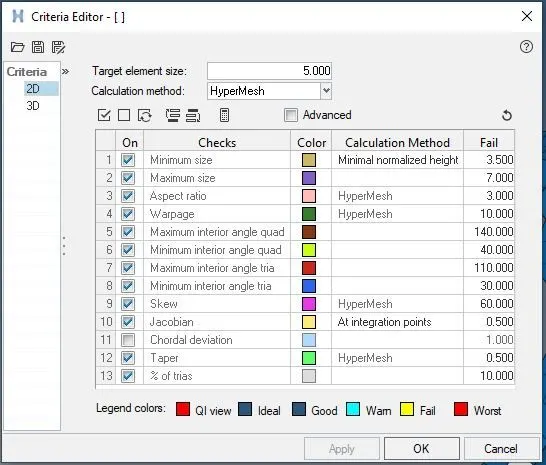
Figure 15: Dialog box that opens after clicking the Preferences → Criteria file settings in the menu bar to set quality parameters of elements.
Discretization or Meshing
Once the quality of elements is set, the next stage is the meshing of the model. To mesh the model, there is an option called ‘automesh’ in the 2D section. Using this tool, the faces of the model are meshed on-by-one. Figures 16 shows the meshing of part 1.
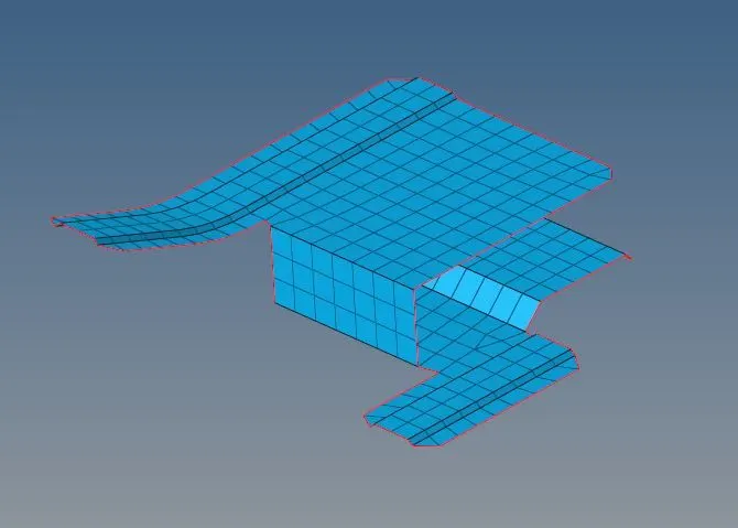
Figure 16: Meshes part 1 with 2d detailed element representation.
Part 2 was symmetric, thus, only half of its part is meshed, as shown in fig. 17(a), and it is reflected using the Tool → reflect option. The result can be seen in fig. 17(b).
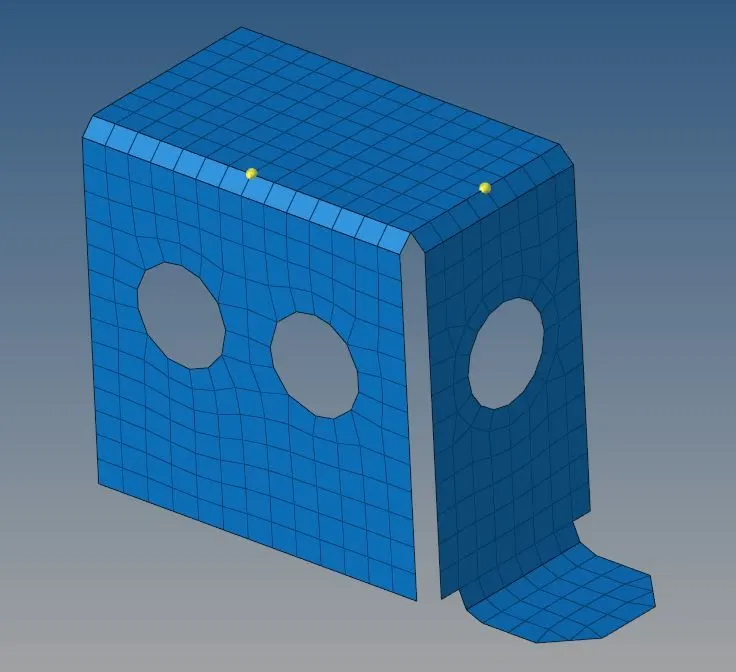
Figure 17: Half meshed part 2.
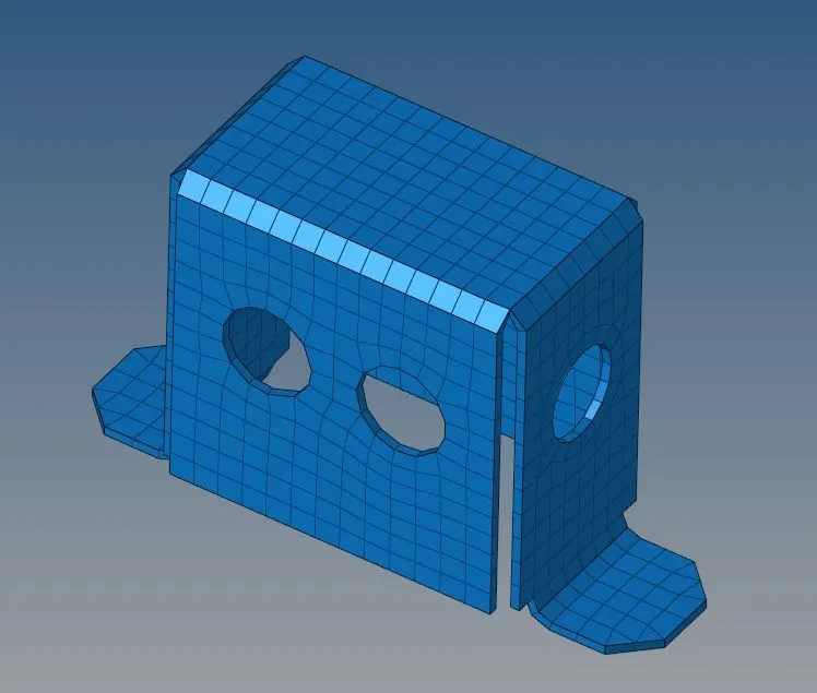
Figure 17(b): Completely meshed part 2 with 2d detailed element representation.
After reflecting the nodes were not connected. It was corrected using the Tool → edges → equivalence option.
Part 3 was symmetric along an axis. Thus, instead of meshing all of its parts, only one side of it is meshed, as can be seen in fig. 18(a), and then the duplicate elements are rotated about the center using the Tool → rotate option. The result can be seen in fig. 18(b).
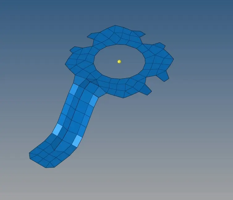
Figure 18(a): Partially meshed part 3.
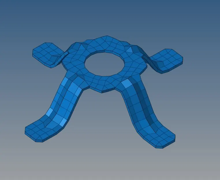
Figure 18: Meshes part 3 with 2d detailed element representation.
After reflecting the nodes were not connected. It was corrected using the Tool → edges → equivalence option.
Quality Check
After completing the meshing part, the last stage of the process is to check if all the elements are within the set criteria or not. To do that, there is an option called ‘elems check’ in the Tool section. When clicked, a window of a set of quality parameters opens as shown in fig. 19.

Figure 19: Window to check failed elements.
Once the failed elements are found it has to be corrected manually, using various tools available in Tool page i.e., translate, rotate, project, etc. or it can be done by using the different tools available in 2D → qualityindex → cleanup tools, as shown in fig. 20.
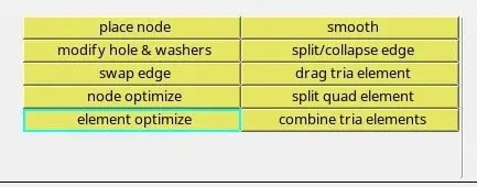
Figure 20: Tools available in qualityindex option to correct the element quality.
One more thing to check in the meshed part is that no free edges are present in between elements apart from the perimeter. Using Tool → edges, free edges can be found out. The free edge is appearing as a red line as shown in fig. 21.
Figure 21: Presence of free edge only at the perimeter and not in between the elements.
The presence of free edge on the perimeter is allowed, however, its presence in between the elements indicates that the elements are not connected. In such a case, elements have to be connected manually. If the distance between nodes is too small, then using Tool → edges → equivalence, elements can be connected. But if the distance is large enough and the nodes also mismatching, then nodes have to be moved to the proper place using 2D → replace tool,
One more thing to check for elements is the direction of their normal. Using Tool → normals, the vector direction of the normals of elements can be checked. Ideally, all vectors should be in the same direction as shown in fig. 22.
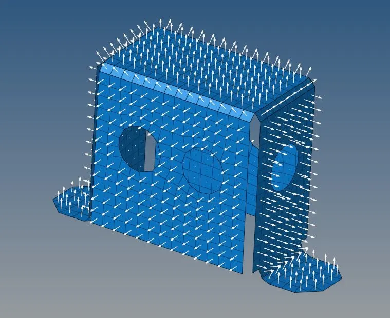
Figure 14: Normal vectors in the same directions.
CONCLUSION
Meshing a model is the primary and important stage of virtual testing. Thus, while meshing the geometry with quad/tria elements, attention should be given to maintain the mesh flow. Because if it has gone wrong, the result would be inaccurate and thus would be the waste of time and money.