Assignment 1-2D Meshing Challenge
AIM:- To study 2D meshing with the help of HYPERMESH.
SOLVER:- Optistruct
OBJECTIVES:-
1) To execute the geometrical cleanup.
2) To extract the mid surface of a given component.
3) To assign quality criteria before meshing.
4) To generate 2D mesh on the given component surface.
5) To eliminate surfaces that may fail for minimum element length.
6) To check for failure of elements from 2D mesh with the help of a quality index tool.
7) To assign proper thickness to the mid surface that we created.
A)PART 1
1. IMPORTING THE GEOMETRY
To import geometry to the hypermesh first we need to switch the solver on which we are going to work here especially working on radios. after changing the solver we will see the components file to check the file format in which they saved here in the given assignments the component files are saved in .hm format and to import them simply we can do to file menu and by clicking on open option we can see the model by clicking on model option hypermesh will take us to the browse directory to entering in the desired file we can see our working file by clicking on open option hypermesh do all the process of generating and reading of the file and withing time the component will visible on the screen.
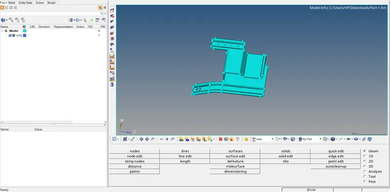
we can see the desired file on the Hypermesh window.
the path we followed to execute this process is,
FILE>OPEN>MODEL>SELECT(selecting the desired file)>OPEN.
moving to the next step.
2. DELETING THE SOLIDS
to delete solids we just simply can go to the delete panel and delete solids from the component so can easily work on surfaces for meshing current file doesn't contain any solids so simply we will move to the next step.
3. GEOMETRICAL CLEANUP
in this process where we simply fix all the geometrical errors which might disturb us in further operations so we simply fixed them one by one to find them easily, we will turn the geometry from auto mode to by topo and we will move into qucki edit panel
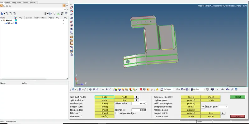
by switching into topo mode we can see there are some yellow lines and red lines which indicate there are some geometrical problems to fix them we will use this quick edit panel.
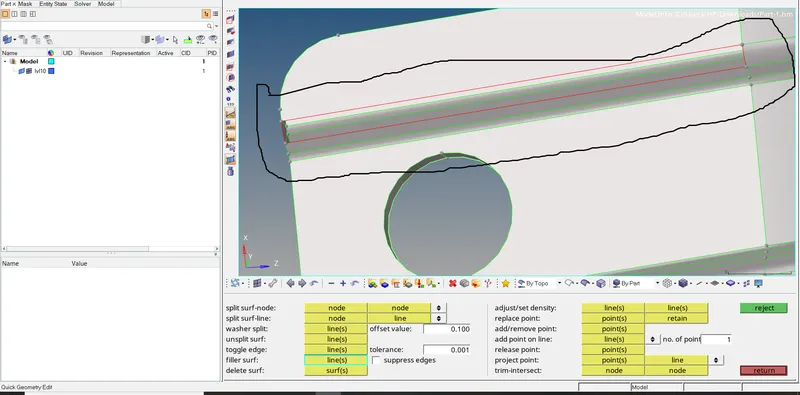
a) the first problem we can see there is a missing surface which we can observe by the red lines to fix that we will use the filler surf tool which will create simply a new surface that was missing by simply clicking on the red line the result we can see in below image,
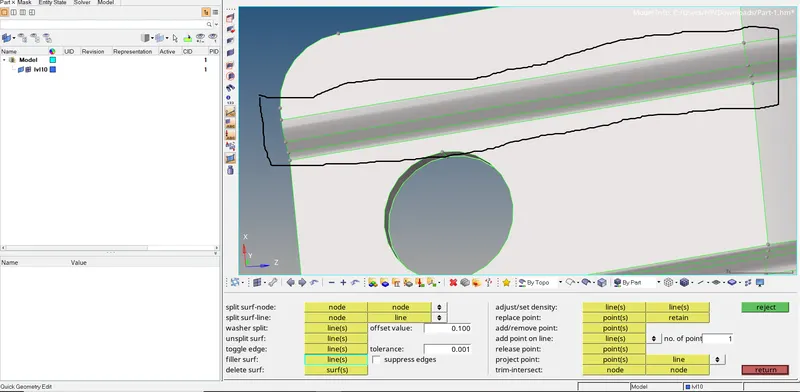
we can see there is a new surface and there are green lines that indicate no error at that location. there is a similar issue we can fix with the same solution.
the path we followed to execute the process
GEOMETRY>QUICK EDIT TOOL>FILLER SURF>LINE(line of the missing surface)>SURFACE FIXED
this is how we fixed this issue.
b)the yellow lines we can see below indicate there are doubled surfaces while construction and to fix that we using a delete panel.
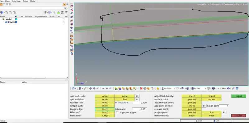
we will move to the delete panel by changing the selecting type as surface and we will select the desired surface and simply click on the delete option the extra surface will get deleted. and there will be no yellow line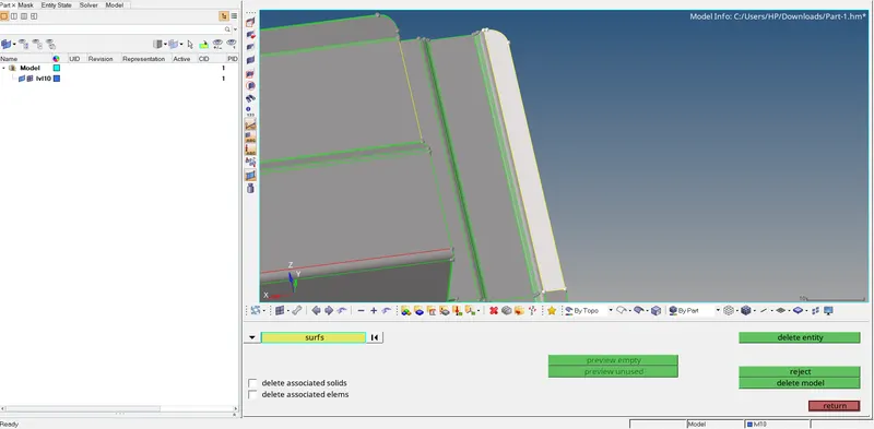
we can see the result in the image below.
the path we follow to fixed this issue,
DELETE PANNEL>SURFACE>DELETE ENTITY
there are some similar issues we can fix with the same method.
c) image below show a geometrical error where we can red line which indicates the two surfaces are having certain gaps that are not stitched properly to fix them we simply use the toggle tool which simply stitches two surfaces.
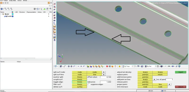
selecting the toggle edge tool we can simply click on the red line the surfaces will get stitched and the tolerance value can change as per the gap between the two surfaces.
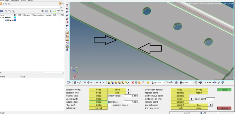
we can see the issue we fixed from the image above.
the path we followed to fix this issue,
GEOMETRY>QUICK EDIT>TOOGLE EDGE>LINE(the line of that surface which we going to fix)>TOLERENCE(we can change the tolerance value as a requirement)>OK
we can fix the same issue by this method.
d)
The below image shows, that there is an additional unwanted part which we want to remove component here we will instead of using delete as it will delete the whole surface we will use replace tool so we will select the point which we want to move and will select the point which we want to retain
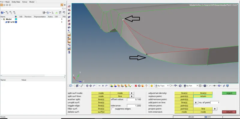
and by clicking on the retain button the point will move to the point which we kept as retain point and our issue will get fixed. As we can see image below,
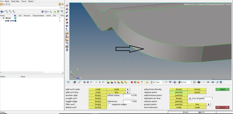
the issue got fixed
through the path we followed to fix this issue.
GEOMETRY>QUICK EDIT>REPLACE POINT>POINT(which we want to move)>RETAIN(the point which keeps at its original location)
to check if is there any problem left we can turn the geometry into wireframe mode and it will be easy to locate the issues and we can fix them by the above methods.
4. EXTRACTING MIDSURFACE:-
so after geometrical cleanup, we will extract the mid surface of a given component to prepare the surface for meshing so here we can either extract mid surface by automatically or manually here the component is not that difficult we can extract my automatically and we use default options so we will move to mid surface tool which is located under geometry panel where we using selecting criteria as surface and we will select the surface altogether and by clicking on extract option hypermesh will start working on it and will extract the mid surface also we can track the process in left corner where the percentage of the process indicates. it actually extracts the exact midsurface of the component so we can carry out the meshing process on that surface for an accurate result.
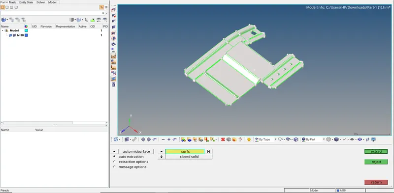
and that surfaces will be saved in a new component called mid surface which is created automatically by hypermesh we can turn off the visibility of the original component and the mid surface will be visible to us.
the path we followed to execute this process is,
GEOMETRY>AUTO MIDSURFACE>SURF(selecting all the surface-displayed)>EXTRACTION OPTION(will be selecting default option)>EXTRACT
surfaces are almost ready for meshing the next process will be defeaturing fillets and holes.
5. APPLYING QUALITY CRITERIA FILE
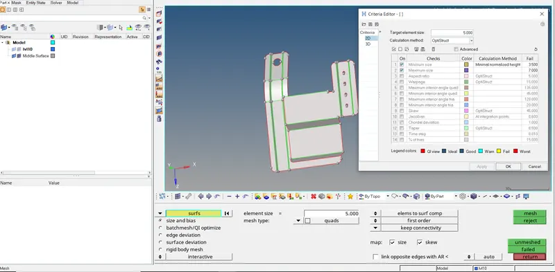
so our given assignments will be focusing on the minimum length and maximum length of the element also the target element size is given so will enter the given data and all the other criteria will be turned off as they are not asked. minimum length is 3.5, the maximum length is 7 and the target element size will be 5 we going to apply this criterion and hit on okay.
6. DEFEATURING FILLETS AND HOLES
here we have two tasks as in the given condition we need to ignore holes and fillets that might fail fo minimum length criteria or create any issue so first, we will deal will fillets
so to defeature the fillets we will go to the defeature tool which is under the geometry tool and in which we will select surface fillets and will put the range for fillets so we will be only deleting the fillets that failed for minimum length so here we start the range from 0.01 to 5 mm and as selecting type we will select the surface which are having fillets then by hitting on find option the fillets will be highlighted and after that window remove window will be displayed by hitting on remove option fillets that we don't want will be eliminated similar way we can defeature the fillets on other surfaces or we can directly select all the displayed surfaces and remove all the fillets at a time.
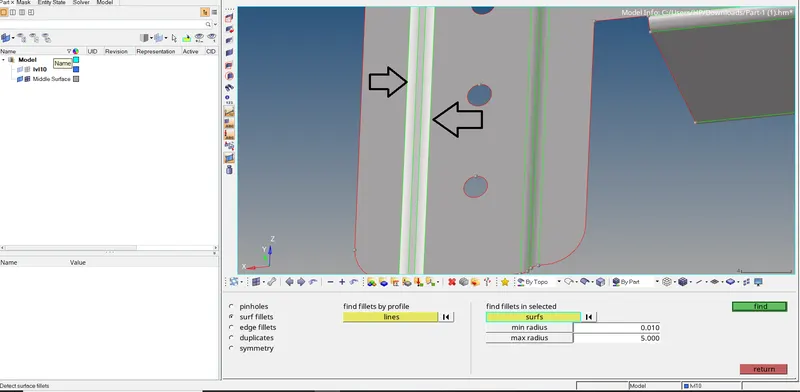
so we can see the image below which show no fillets within the range from 0.01 to 5 mm or we defeatured successfully the fillets which may fail for minimum length.
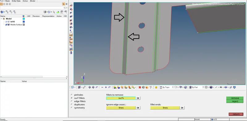
we can see the results similar way we going to remove all the fillets which we want to remove.
the path we followed to remove fillets,
GEOMETRY>DEFEATURE>SURF FILLETS>SURF(selecting type as)>RANGE(mini to max radius)>FIND>REMOVED
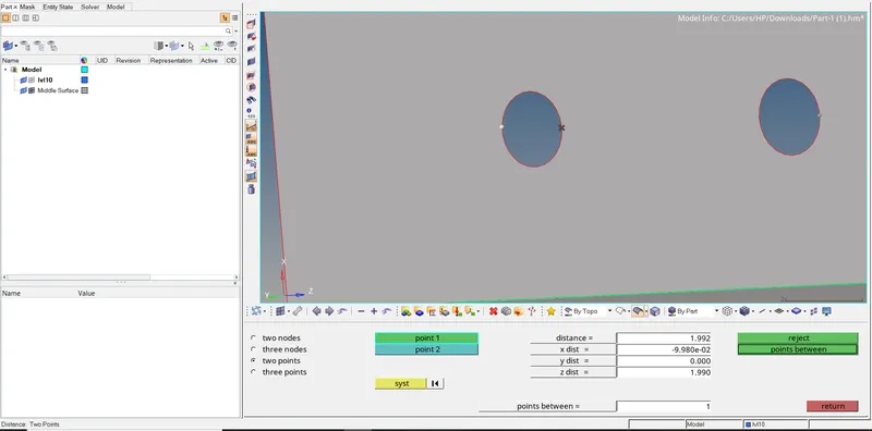
defeaturing t holes which may trouble us while meshing around the so identify which hole we need to remove for that we will use the distance tool where we are going to use the two-point option so we can select two points on the circumference of the hole and can see the distance is displayed window and we are going to defeature those holes.
we will move to the quick edit tool and use the filler surf and by clicking on the edge of the hole will be filled with a new surface that we can see in the image below,
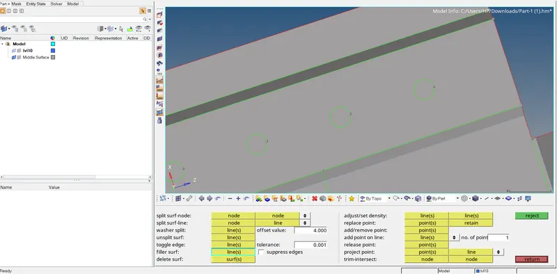
we can simply toggle the green circular lines to eliminate.
finally, we did all the processes before meshing the surface now we will move to the mesh panel
7. GENERATING 2D MESH
for that, we will enter into the automesh panel under the 2D panel and will set up all the settings such as element size as 5 and mesh type as a quad and we will select the target surface which we want to mesh, and the mesh will be generated on that surface to get better mesh flow we can change the no of elements on either side by equalizing them we can get quad elements which will help further process for accurate results also we can use smooth option for better mesh flow the main focus will be eliminating the maximum trias as much as possible.
also, we can use the drag tria option under the quality index tool,
we can eliminate trias by opposite trias and rebuilding the elements around them that will help us to eliminate the trias and create a quad element,
also, we can use the combine element option so we can combine two adjacent trias to create a quad.
this method will help us to get a better mesh to flow with fewer trias elements
we can see the image below indicating better mesh flow with no trias as an example,
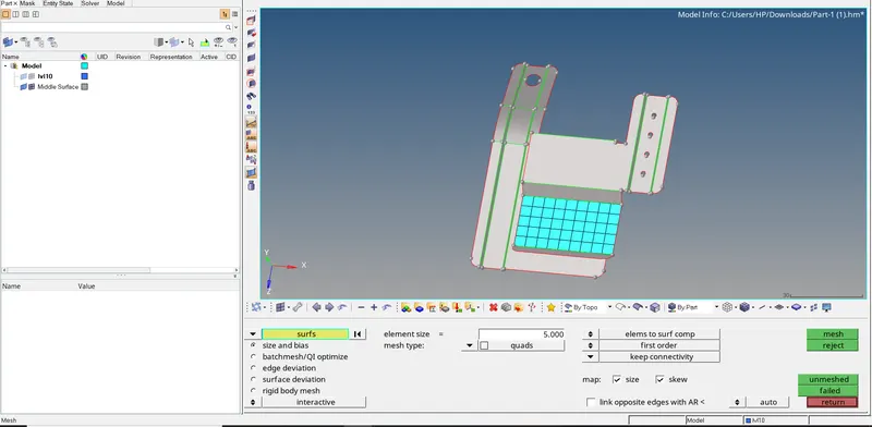
one by one we can mesh the whole surface of the component. after finishing the mesh we will move to the quality index and check for failed elements.
To mesh the components we used the auto mesh command,
2D>AUTOMESH>SURF(selected the targeted surfaces)>ELEMENT SIZE(5)>ELEMENT TYPE(MIXED)>MESH
8. QUALITY INDEX
so to access the quality index we will move to the 2D panel,
The Quality Index value is a function of twelve criteria with user-defined weight factors. Each criterion has five rating levels. HyperMesh assigns a penalty value to each element according to its rating for individual criteria.
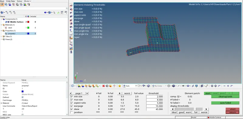
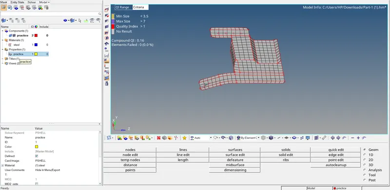
so we can see from the image above that no elements are failing and the no of elements that failed is zero and obvious the failed percentage is zero and also compound quality index is 0.02,
after all this procedure we will move to Assign material and properties to the component,
9. ASSIGNING MATERIAL AND PROPERTIES:-
so to assign material and properties we can simply add material and property by right-clicking into the model tree region
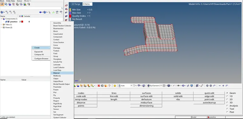
so we successfully added the material and property and will be keeping the values as default values as we only using this for study purposes after adding we need to assign both material and properties to a given component.
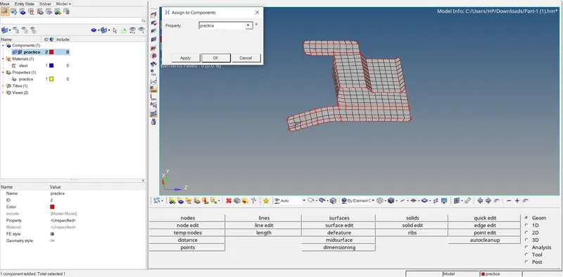
so by right-clicking on the component, we can see, that there is an assigned tool by clicking on that we can see a small window getting pop-up so selecting the appropriate material and property will be clicking on apply button, and hitting ok will confirm the setting.
and assigning thickness and other values keeping as deault values
10. FINAL RESULT:-
******************************************************************************************
B.PART II
1. IMPORTING THE GEOMETRY
To import geometry to the hypermesh first we need to switch the solver on which we are going to work here especially working on radios. after changing the solver we will see the components file to check the file format in which they saved here in the given assignments the component files are saved in .hm format and to import them simply we can do to file menu and by clicking on open option we can see the model by clicking on model option hypermesh will take us to the browse directory to entering in the desired file we can see our working file by clicking on open option hypermesh do all the process of generating and reading of the file and withing time the component will visible on the screen.
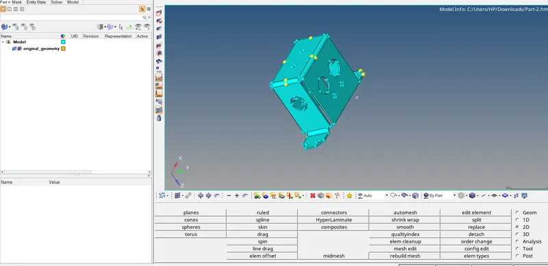
we can see the desired file on the Hypermesh window.
the path we followed to execute this process is,
FILE>OPEN>MODEL>SELECT(selecting the desired file)>OPEN.
moving to the next step.
2. DELETING THE SOLIDS
to delete solids we just simply can go to the delete panel and delete solids from the component so can easily work on surfaces for meshing current file doesn't contain any solids so simply we will move to the next step.
3. GEOMETRICAL CLEANUP
we will change the geometrical mode from auto to topo mode and we can see there are no such geometrical errors and nothing to be fixed we will move further.
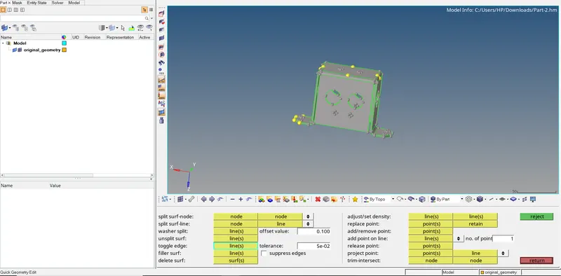
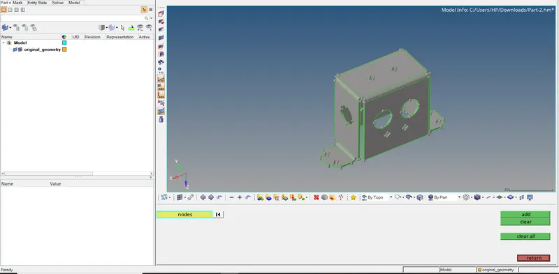
there are some nodes are present on the component we will try to clear them with the help of the temp node tool by selecting them all together by clicking shift and clicking the left mouse button at the same time dragging the mouse button until we cover all the nodes till we see all the yellow color nodes turn into white nodes and by clicking on clear button nodes will be clear.
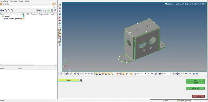
below the image, we can see there are no nodes present on the component,
4. EXTRACTING MIDSURFACE:-
we will use here manual midsurfacing process so we will discover both processes in the same assignment so to extract the mid-surface manually first we need to calculate the thickness of the component. for that we will enter into distance tool and we will choose a two-point option and select two points on the edges which indicate the thickness of the component and similar way we check another region on confirming our thickness value and after this, we will move to surface edit panel where we will use offset tool so we will put the offset value which is half of the thickness and select the surface of the component which we want to offset to extract mid surface but while selecting the surface we will duplicate them as we want to keep original surfaces at their places so we will duplicate the surface and save the duplicated surface into the new component which we creating with name middle surface and setting them as current operating component and we will first notice the vector direction in which direction this surfaces going either away from component or towards the centre and will chose the vector direction which going towards the centre and our mid surface will be created by turning our parent geometry we can see our mid surface similar way we can take mid surfaces of the whole component.
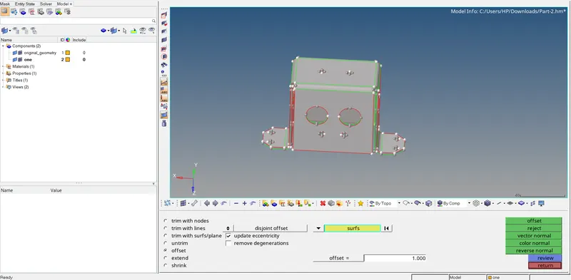
we can see our mid surface is created to make it visible we will be turning off our parent geometry,
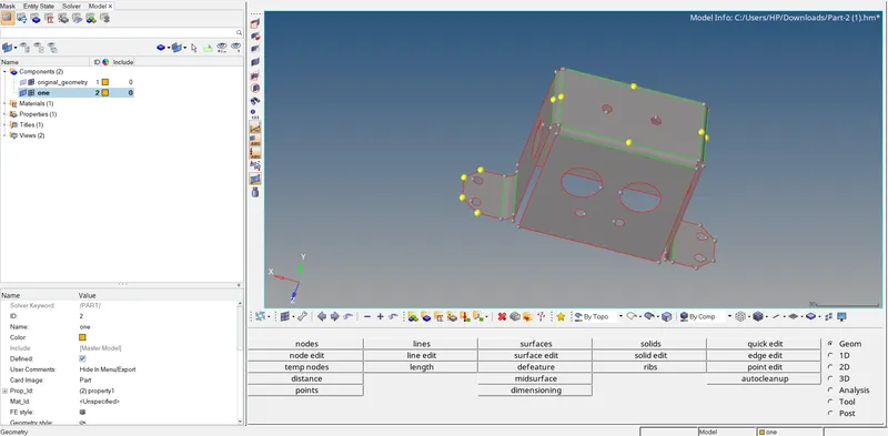
so we completed with extracting midsurface,
the path we followed to extract the midsurface is
GEOMETRY>SURFACE EDIT>OFFSET>SURFACE(selecting the surface which we want to extract and we will duplicate that surface and save it into the newly created component)>OFFSET VALUE(putting offset value which we calculated>VECTORE DIRECTION(selecting the proper vector direction from given option)>OFFSET
5. DEFEATURING FILLETS AND HOLES
as there is no fillet which troubles us to fall for minimum length element failure we will not defeaturing any fillets but there are some holes are less than the criteria of the hole to defeature so we will remove them
defeaturing t holes which may trouble us while meshing around the so identify which hole we need to remove for that we will use the distance tool where we are going to use the two-point option so we can select two points on the circumference of the hole and can see the distance is displayed window and we are going to defeature those holes.
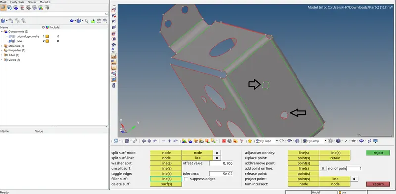
we will move to the quick edit tool and use the filler surf and by clicking on the edge of the hole will be filled with a new surface that we can see in the image below,
image
we can simply toggle the green circular lines to eliminate them.
finally, we did all the processes before meshing the surface now we will move to the mesh panel.
6. APPLYING QUALITY CRITERIA FILE
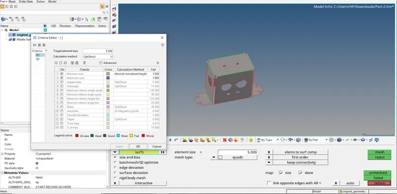
so our given assignments will be focusing on the minimum length and maximum length of the element also the target element size is given so will enter the given data and all the other criteria will be turned off as they are not asked. minimum length is 3.5, the maximum length is 7 and the target element size will be 5 we going to apply this criterion and hit on okay.
7. GENERATING 2D MESH
for that, we will enter into the automesh panel under the 2D panel and will set up all the settings such as element size as 5 and mesh type as a quad and we will select the target surface which we want to mesh, and the mesh will be generated on that surface to get better mesh flow we can change the no of elements on either side by equalizing them we can get quad elements which will help further process for accurate results also we can use smooth option for better mesh flow the main focus will be eliminating the maximum trias as much as possible.
also, we can use the drag tria option under the quality index tool,
we can eliminate trias by opposite trias and rebuilding the elements around them that will help us to eliminate the trias and create a quad element,
also, we can use the combine element option so we can combine two adjacent trias to create a quad.
this method will help us to get the better mesh to flow with fewer trias elements
we can see the image below indicating better mesh flow with no trias as an example,
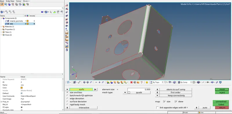
so we selected the surface and changed the settings as per requirement we here keep all the default settings other than element size and element type and click on mesh button and mesh will be generated.
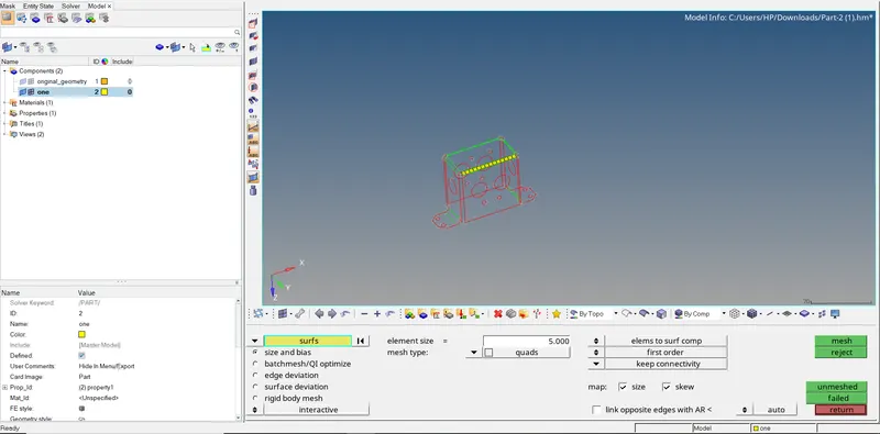
one by one we can mesh the whole surface of the component. after finishing the mesh we will move to the quality index and check for failed elements.
8. QUALITY INDEX
so to access the quality index we will move to the 2D panel,
The Quality Index value is a function of twelve criteria with user-defined weight factors. Each criterion has five rating levels. HyperMesh assigns a penalty value to each element according to its rating for individual criteria.
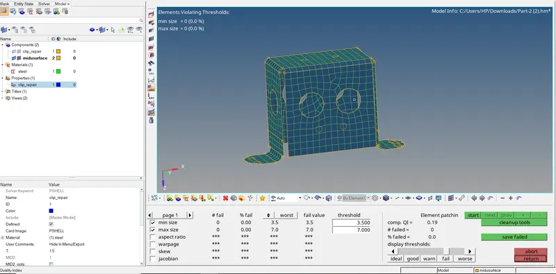
so we can see from the image above that no elements are failing and the no of elements that failed is zero and obvious the failed percentage is zero and also compound quality index is 0.19.
after all this procedure we will move to Assign material and properties to the component,
9. ASSIGNING MATERIAL AND PROPERTIES:-
so to assign material and properties we can simply add material and property by right-clicking into the model tree region
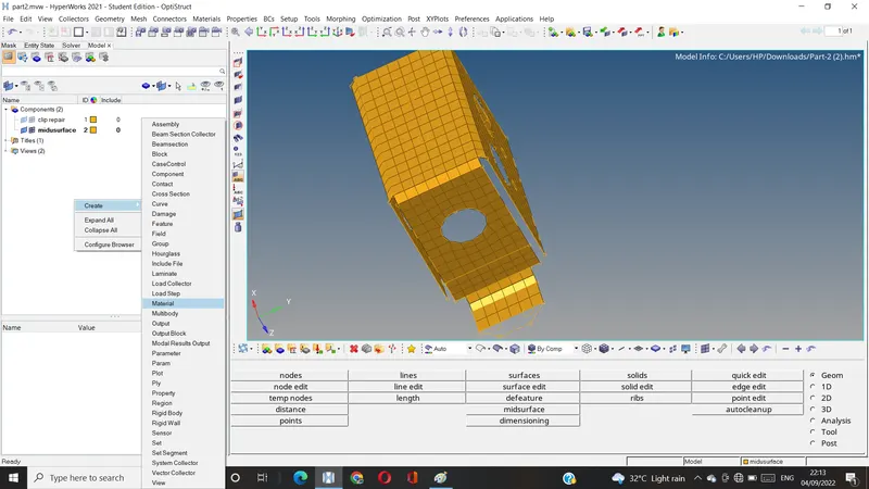
so we successfully added the material and property so will be keeping the values as default values as we only using this for study purposes after adding we need to assign both material and properties to a given component.
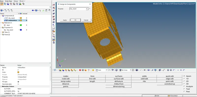
so by right-clicking on the component, we can see, that there is an assigned tool by clicking on that we can see a small window getting pop-up so selecting the appropriate material and property will be clicking on apply button, and hitting ok will confirm the setting and assigned thickness value.
10. Final Result:-
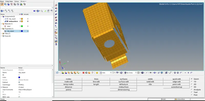
*****************************************************************************************
C. PART 3
1. IMPORTING THE GEOMETRY
To import geometry to the hypermesh first we need to switch the solver on which we are going to work here especially working on radios. after changing the solver we will see the components file to check the file format in which they saved here in the given assignments the component files are saved in .hm format and to import them simply we can do to file menu and by clicking on open option we can see the model by clicking on model option hypermesh will take us to the browse directory to entering in the desired file we can see our working file by clicking on open option hypermesh do all the process of generating and reading of the file and withing time the component will visible on the screen.
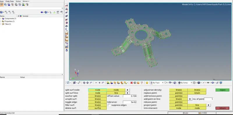
we can see the desired file on the Hypermesh window.
the path we followed to execute this process is,
FILE>OPEN>MODEL>SELECT(selecting the desired file)>OPEN.
moving to the next step.
2. DELETING THE SOLIDS
to delete solids we just simply can go to the delete panel and delete solids from the component so can easily work on surfaces for meshing current file doesn't contain any solids so simply we will move to the next step.
3. GEOMETRICAL CLEANUP
we will change the geometrical mode from auto to topo mode and we can see there are no such geometrical errors and nothing to be fixed we will move further.
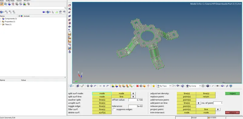
so we will move to the next step which is mid-surface extraction.
4. EXTRACTING MIDSURFACE:-
we will use here manual midsurfacing process so we will discover both processes in the same assignment so to extract the mid-surface manually first we need to calculate the thickness of the component. for that we will enter into distance tool and we will choose a two-point option and select two points on the edges which indicate the thickness of the component and similar way we check another region on confirming our thickness value and after this, we will move to surface edit panel where we will use offset tool so we will put the offset value which is half of the thickness and select the surface of the component which we want to offset to extract mid surface but while selecting the surface we will duplicate them as we want to keep original surfaces at their places so we will duplicate the surface and save the duplicated surface into the new component which we creating with name middle surface and setting them as current operating component and we will first notice the vector direction in which direction this surfaces going either away from component or towards the centre and will chose the vector direction which going towards the centre and our mid surface will be created by turning our parent geometry we can see our mid surface similar way we can take mid surfaces of the whole component.
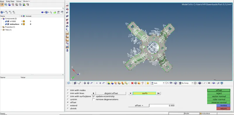
we can see our mid surface is created to make it visible we will be turning off our parent geometry,
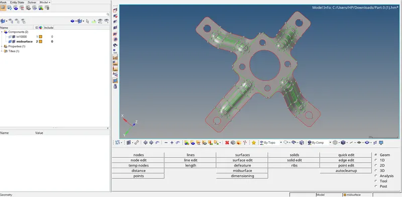
so we completed with extracting midsurface,
the path we followed to extract the midsurface is
GEOMETRY>SURFACE EDIT>OFFSET>SURFACE(selecting the surface which we want to extract and we will duplicate that surface and save it into the newly created component)>OFFSET VALUE(putting offset value which we calculated>VECTORE DIRECTION(selecting the proper vector direction from given option)>OFFSET
5. DEFEATURING FILLETS AND HOLES
here we have two tasks as in the given condition we need to ignore holes and fillets that might fail fo minimum length criteria or create any issue so first, we will deal will fillets
so to defeature the fillets we will go to the defeature tool which is under the geometry tool and in which we will select surface fillets and will put the range for fillets so we will be only deleting the fillets that failed for minimum length so here we start the range from 0.01 to 5 mm and as selecting type we will select the surface which are having fillets then by hitting on find option the fillets will be highlighted and after that window remove window will be displayed by hitting on remove option fillets that we don't want will be eliminated similar way we can defeature the fillets on other surfaces or we can directly select all the displayed surfaces and remove all the fillets at a time.
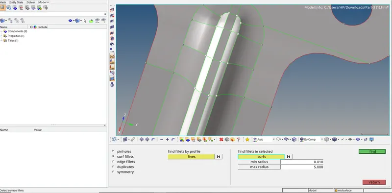
so we can see the image below which show no fillets within the range from 0.01 to 5 mm or we defeatured successfully the fillets which may fail for minimum length.
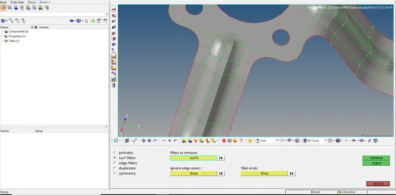
we can see the results similar way we going to remove all the fillets which we want to remove.
the path we followed to remove fillets,
GEOMETRY>DEFEATURE>SURF FILLETS>SURF(selecting type as)>RANGE(mini to max radius)>FIND>REMOVED
defeaturing t holes which may trouble us while meshing around the so identify which hole we need to remove for that we will use the distance tool where we are going to use the two-point option so we can select two points on the circumference of the hole and can see the distance is displayed window and we are going to defeature those holes.
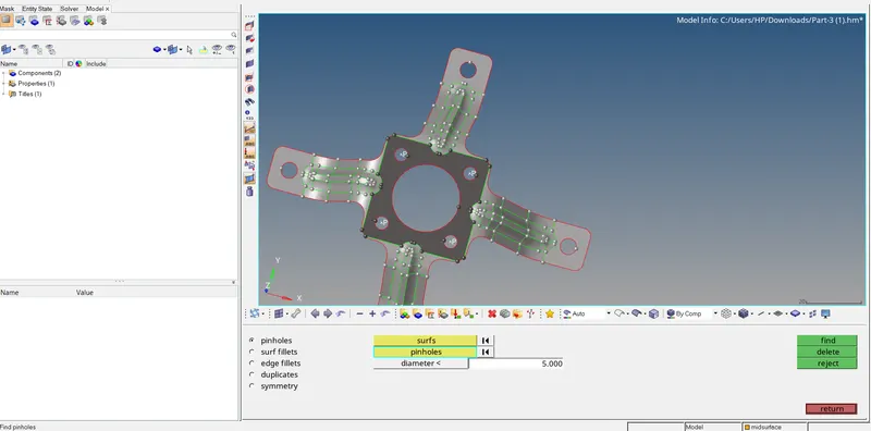
we will move to the defeature tool and select surface and pinholes ranging opto 5mm find and delete
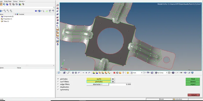
we can simply toggle the green circular lines to eliminate.
finally, we did all the processes before meshing the surface now we will move to the mesh panel.
6. APPLYING QUALITY CRITERIA FILE
so our given assignments will be focusing on the minimum length and maximum length of the element also the target element size is given so will enter the given data and all the other criteria will be turned off as they are not asked. minimum length is 3.5, the maximum length is 7 and the target element size will be 5 we going to apply this criterion and hit on okay.
7. 2D MESHING:-
for that, we will enter into the automesh panel under the 2D panel and will set up all the settings such as element size as 5 and mesh type as a quad and we will select the target surface which we want to mesh, and mesh will be generated on that surface to get better mesh flow we can change the no of elements on either side by equalizing them we can get quad elements which will help further process for accurate results also we can use smooth option for better mesh flow the main focus will be eliminating the maximum trias as much as possible.
also, we can use the drag tria option under the quality index tool,
we can eliminate trias by opposite trias and rebuilding the elements around them that will help us to eliminate the trias and create a quad element,
also, we can use the combine element option so we can combine two adjacent trias to create a quad.
this method will help us to get the better mesh to flow with fewer trias elements
we can see the image below indicate better mesh flow with no trias as an example,
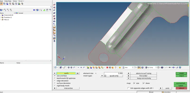
In the image below we can see how we initiated the mesh,
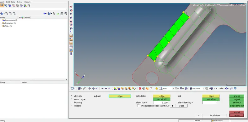
by clicking the middle mouse button will be accepting the mesh to get all the quads we change the no of elements till we get quads to avoid tria elements.
2D > AUTOMESH > SURFACE (desired surface) < ELEMENT SIZE ( element size 5 as given) > MESH STYLE (QUAD) > MESH
there are many other ways to avoid tria or to create a maximum quad element.
8. QUALITY INDEX
so to access the quality index we will move to the 2D panel,
The Quality Index value is a function of twelve criteria with user-defined weight factors. Each criterion has five rating levels. HyperMesh assigns a penalty value to each element according to its rating for individual criteria.
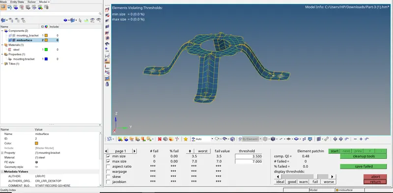
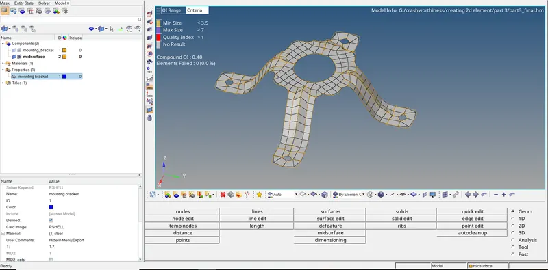
so we can see from the image above that no elements are failing and the no of elements that failed is zero and obvious the failed percentage is zero and also compound quality index is 0.48,
after all this procedure we will move to Assign material and properties to the component,
9. ASSIGNING MATERIAL AND PROPERTIES:-
so to assign material and properties we can simply add material and property by right-clicking into the model tree region
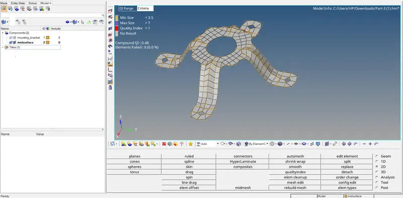
so we successfully added the material and property so will be keeping the values as default values as we only using this for study purposes after adding we need to assign both material and properties to a given component.
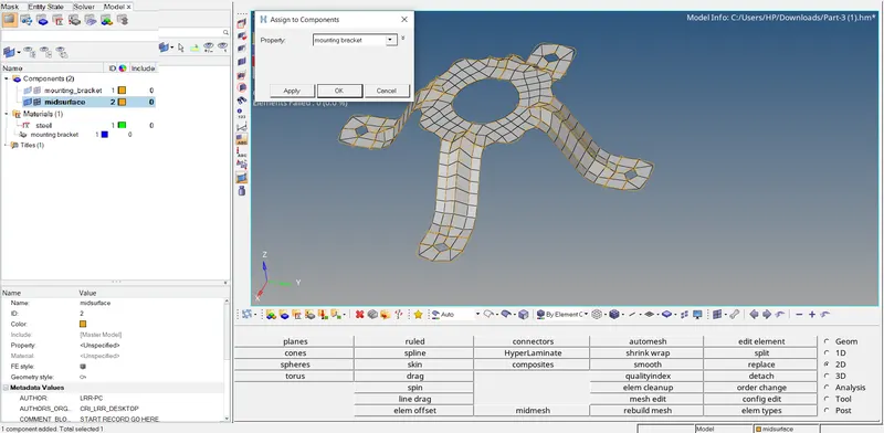
so by right-clicking on the component, we can see, that there is an assigned tool by clicking on that we can see a small window getting pop-up so selecting the appropriate material and property will be clicking on apply button, and hitting ok will confirm the setting and also we added thickness value.
10. FINAL RESULT:-
D. CONCLUSION:-
1. we successfully resolved all the geometrical errors.
2. we extract midsurface successfully.
3. we manage to achieve better mesh within the given quality criteria.
4. we assigned material and properties.
(NOTE:- All the files related to this challenge are attached below.)