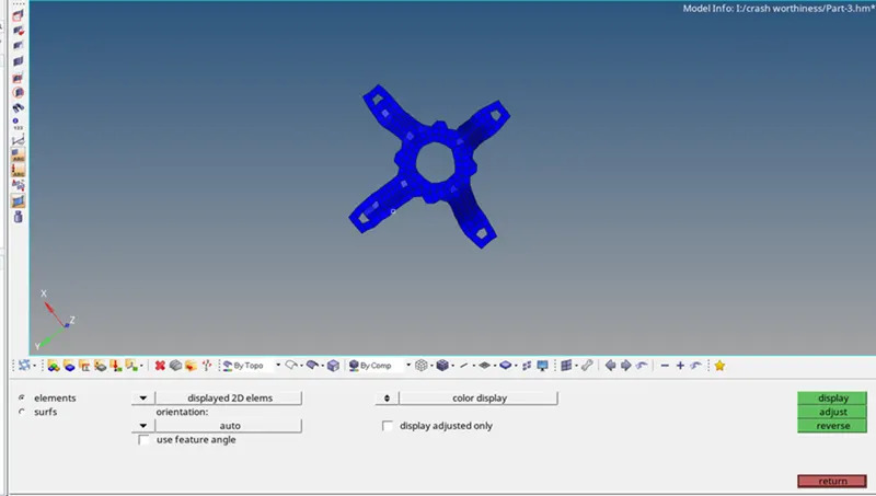
Assignment 1-2D Meshing Challenge
Objective:
- Carry out geometry clean-up operation on the given models.
- Extract mid surface.
- Clean mid-surface geometry.
- Ignore holes less than diameter
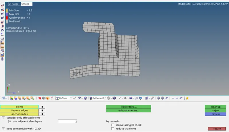
- Create a 2D mesh with target length 5mm, min 3.5mm max 7mm.
- Assign proper thickness, by creating a generic property.
- Save in .hm format.
Procedure
Part 1:
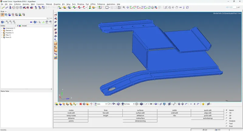
Imported file of model 1 in hyper mesh using import file option
Step 1: Topo view mode
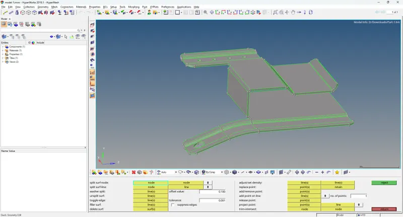
The given model is viewed in top mode to view the surface edges.press f11 key for shortcut
Step 2: Geometry clean-up
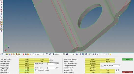
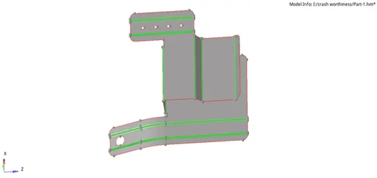
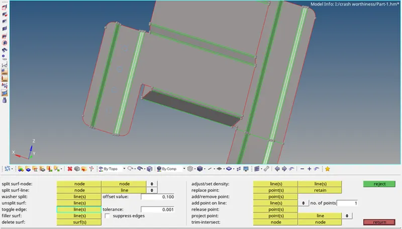
Above view shows the surface irregularities in the imported model, it should be cleared before the mid surface of the model is obtained. The geometric clean-up of the imported model is done using the following tools: For missing surfaces, the filler surf option under the quick edit tab is used For Disconnected edges, the toggle edge option under the quick edit tab is used. Increase the tolerance. don’t directly increase the tolerance value slowly only increase (F11)
Step 3: Extraction of mid surface
The next step is to extract the mid-surface. The mid-surface is available in the geometry panel After opening the mid-surface tool, the surfaces should be selected and the option used to extract the mid surface is offset+planes+sweeps. And the mid-surface panel the extracted mid-surface
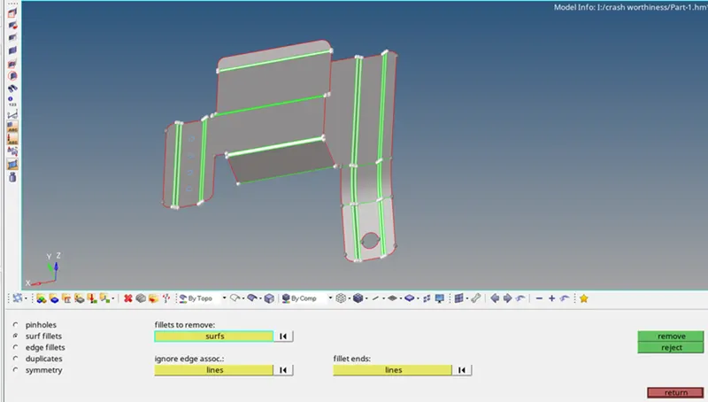
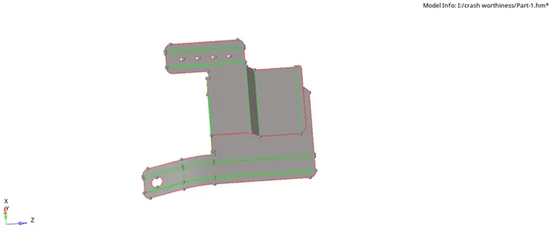
The next step is to find out any surface fillet will lead to minimum element size error and defeature those fillets through the defeature option. Then, some holes are noticed with a minute diameter. The radius can be founded by the Distance option (Keyboard Short-cut is F4). In that, the distance with three nodes should be selected. And by placing the nodes on that free edge, will show the radius of that hole. With the help of this radius, the diameter can be known. We can ignore the holes less than 5 mm
Step 4: Generating mesh
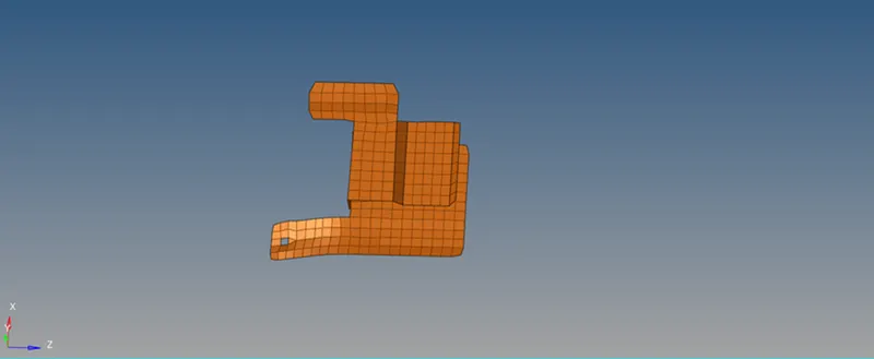
After geometry clean up, the next step is to generate the mesh. Before generating the mesh, there are some prerequisites. They are filling up the criteria editor. The meshing is done by using auto mesh tool under the 2-D tab with elements size as 5 and element type as mixed. The meshing of each component is done surface wise from one small surface. Similarly, meshing is progressed into adjacent attached surfaces to mesh the whole model
 Step 5: Quality index
Using the quality index tool, all components' mesh elements are verified. The elements that do not meet the required quality requirements have yellow and red markings. To optimise the infringing elements, optimization methods like element optimise and position node inside the quality index are applied. The Elem cleaning tool is used for elements that, after optimization using the quality index tool, are not within the criterion range. The auto mesh tool is used to Ramesh the non-optimized elements in cases when the quality index and Elem cleaning tools were unable to correct the violating elements. If any further infringing elements are found, the elements of all components are examined. The procedures above are repeated until all items meet the specified quality standards, if they are present.
Step 5: Quality index
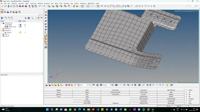
Model 2
IMPORT:
Given model is imported to Hyperworks using import model option.
Step 1: Topo view mode
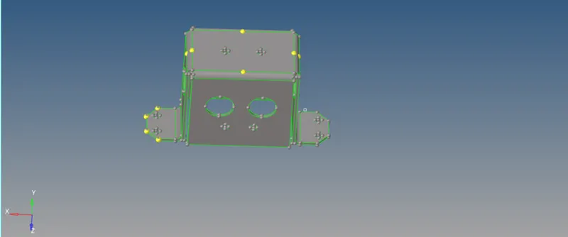
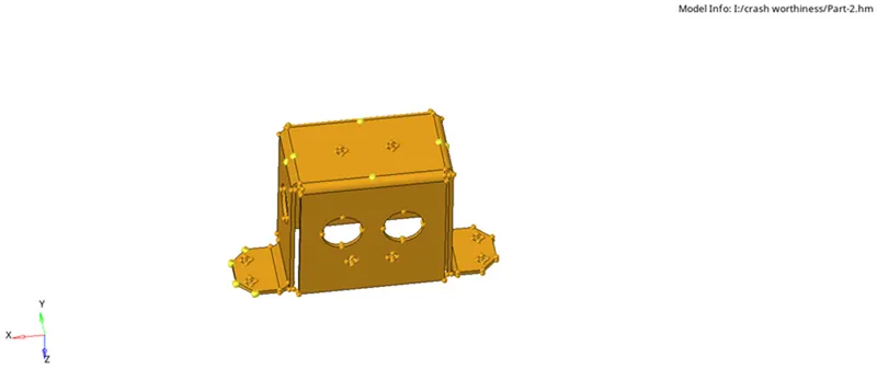
The given model is viewed in topo mode to view the surface edges.
Step 2: Geometry clean-up
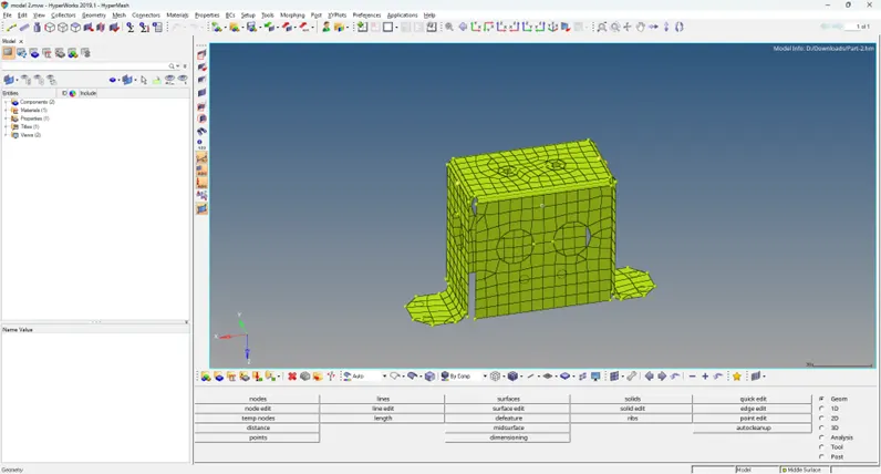
The model part2 when viewed under topo mode does not have any sort of geometrical error hence no geometry correction was required.Md-surface The Mid-surface of the closed solid is extracted using the Surface-edit tool under the geometry tab. the Mid surface is used to obtain the mid-surface with an offset option.Mi surface generated is stored under an initial collector. we need to move to another component
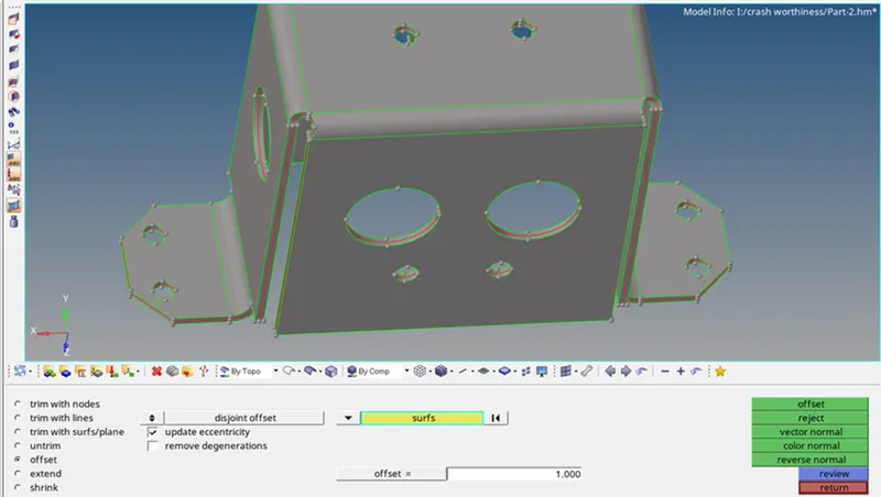
The extracted mid-surface is shown below placed exactly in the middle of the given model
Step 3: Extraction of mid surface
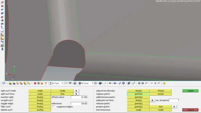
There are some regions that have Which leads to the violation of quality criteria. This can be overcome by replacing those points. This replacement option is available in the quick edit panel
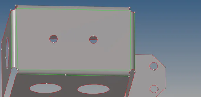
The holes with a diameter less than 5mm can be ignored.
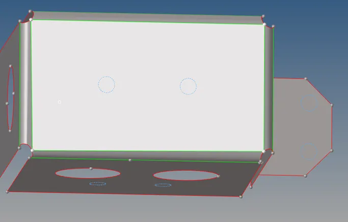
Step 4: Generating mesh
In order to mesh the component faster, only some surfaces have meshed. For the remaining surfaces, the elements are reflected.

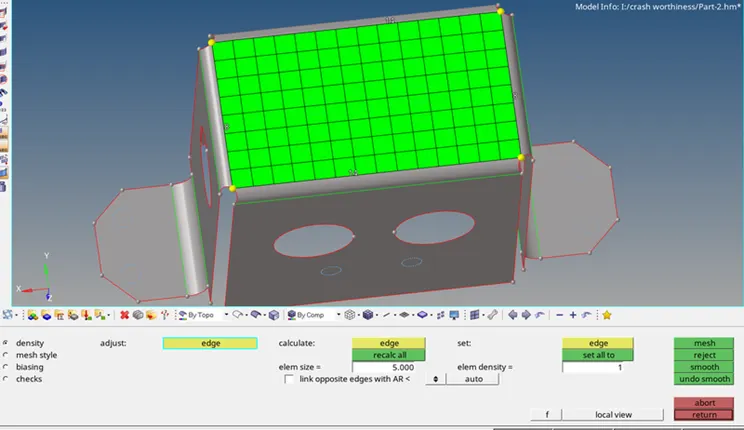
The reflect option is available in the "Tool" panel
The elements to be reflected are duplicated, the direction to which the elements should be reflected(Y-axis) & the base point is selected at the center. After reflecting the elements on one side, the component
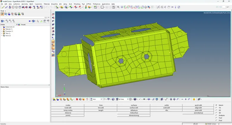
And the quality criteria are verified. The elements failing are shown as zero.
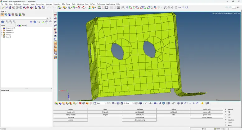
Even though the component is meshed fully by using reflect option, there will be a gap and no connectivity between the nodes. This can be noticed by the option "Find edges". In that, the elements which are reflected are to be selected and clicking on preview equivalence. The next step is to verify the free edges. It is also verified by the "find edges" option. The obtained free edges. The next step is to check for normal. The normal are checked in the same way as done for component
Part 3
IMPORT:
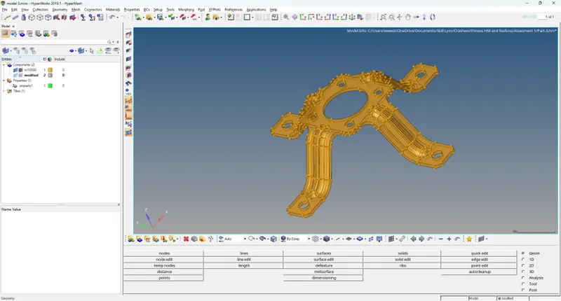
Given model is imported to Hyper works using import model option.
Step 1: Topo view mode
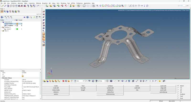
The given model is viewed in topo mode to view the surface edges.
Step 2: Geometry clean-up
The model part-3 when viewed under topo mode does not have any sort of geometrical error hence no geometry correction was required.
Step 3: Extraction of mid surface
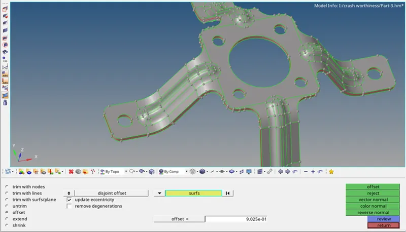
The Mid-surface of the closed solid is extracted using the Surface-edit tool under the Geometry tab.
the Mid surface is used to obtain the mid-surface with an offset option.
Midsurface generated is stored under an initial collector. we need to move to another component
The extracted mid-surface is shown below placed exactly in the middle of the given model
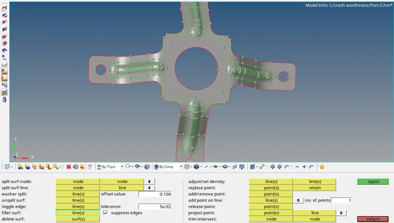
Geometry clean-up is done with the help of the auto cleanup tool under the Geometry tab.
Some of the edges are manually suppressed using the toggle edge option under the quick edit panel.
Larger surfaces are further divided using a split surf-node/split surf-line option under the quick edit panel to obtain a proper mesh.
Holes up to 5mm diameter is avoided by using the filler surf tool under the quick edit tab.
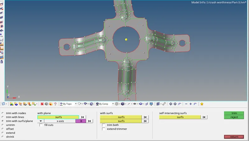
The next step is to take a midline in between two surfaces with trim with surface/plane options on both sides
Step 4: Generating mesh
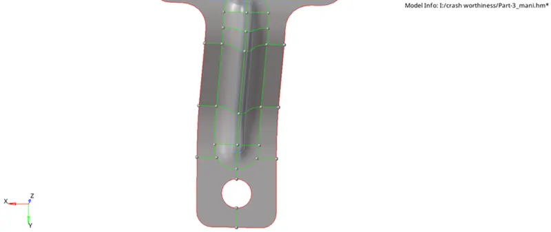
The next step is to generate the mesh. In order to mesh faster with proper mesh flow, only some surfaces have meshed.
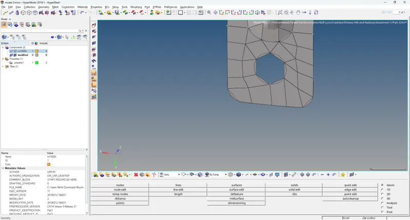
The mesh near the holes is to be rotated. In order to obtain the proper mesh flow.
QUALITY Check:
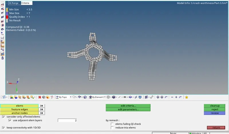
The meshed elements of all components are checked using the quality index tool.
The elements violating the specified quality criteria are marked yellow and red.
Cleanup tools like element optimize and place node within the quality index is used to optimize the violating elements.
For elements that are not optimized to within the criteria range with the quality index tool, the Elem cleanup tool is used.
In situations where quality index and elem cleanup tools failed to rectify the violating elements, the auto mesh tool is used to remesh the non-optimized elements.
The elements of all components are checked if any more violating elements are present.
If present, the above steps are repeated until all elements fall under the given quality criteria.
The next step is to check for free edges.
Then, it's time to check for the normals. The normals for the given component with the color display